Component :: Programmable Bending
How can give simple instructions for precisely folded angles?
Concept
The final book in David Gingery's series Build Your Own Metal Working Shop From Scrap is Book 7,
Building The Sheet Metal Brake. Starting from the simple three-leaf design described therein, I want to
iterate through the implementation of numeric control over the folding process.
To-do List
- Rapid prototype the analog Gingery brake as a starting point.
- bed leaf (15-30", length TBD)
- bending leaf (lever arm controlled)
- clamping leaf (pivot positioning to correspond to metal gauge, TBD)
- tabletop mountable
- Add numeric control through spiral development.
- servo-electric clamping and bending mechanisms to work with light gauge sheet metal.
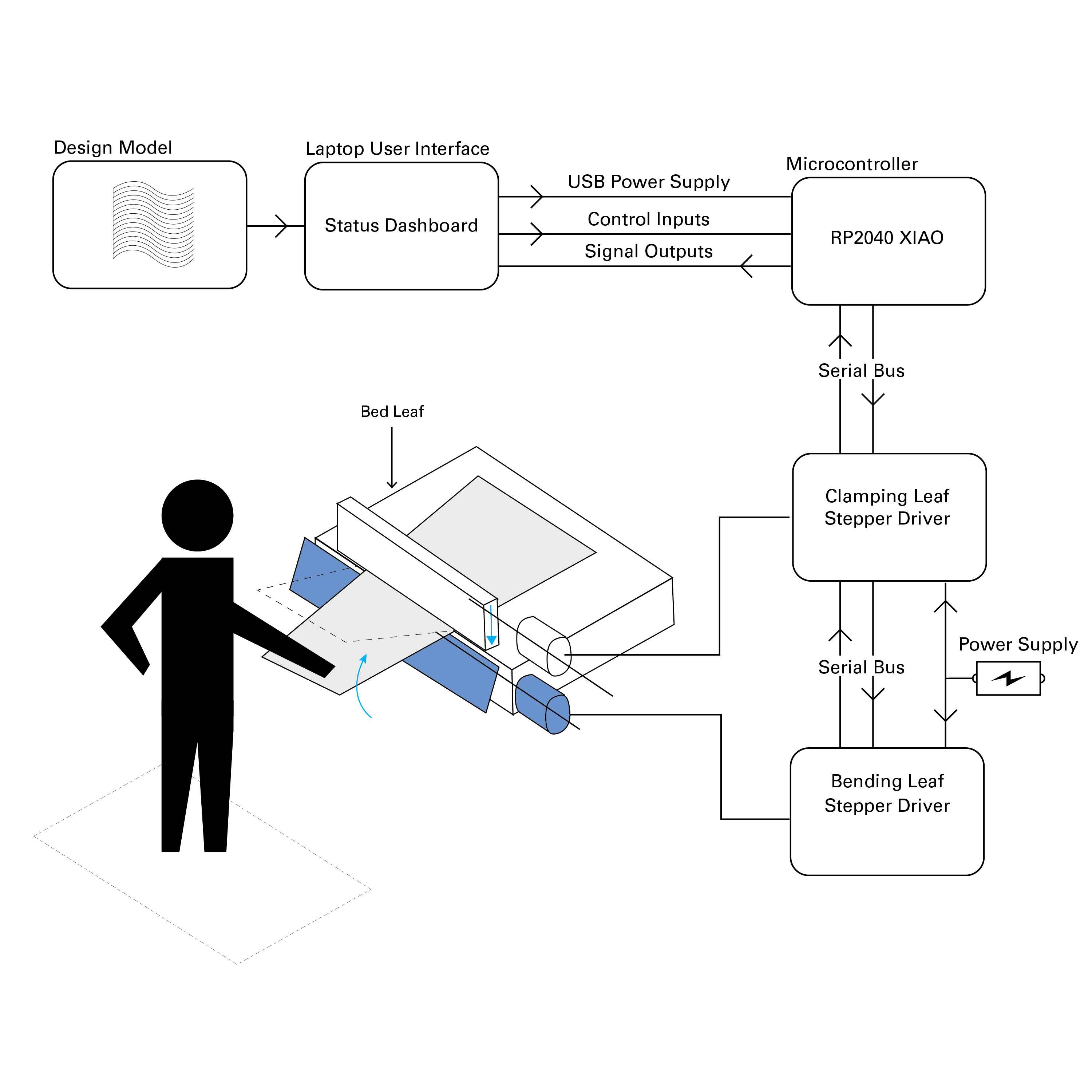
- RP2040 xiao to control two stepper motors?
- Stationary tabletop-edge mounted bed with two pivoting metal leaves.
- toggle option for manual versus CNC operation
 Fig. 1-1. Proposed Component Scope
Linkage Simulation
Fig. 1-6. Linkage Simulation
Simulation built in grasshopper.
In this clip, you can see that the linkage exhibits a toggle behavior as the clamping leaf closes.
I thought this might have been a mistake in how I copied the parts into CAD, because the radii intersect at two points,
which causes the jump in the simulation. To understand this behavior, I thought it was a good time to build a physical prototype to
check for myself what this linkage was doing.
Calculations
How do I know how much force this will require?
Since this machine is more similar to a wiper-die rather than a v-die, we can get a sense of the force requirements for the bending
operation by consulting a
Wipe-Bending-Force Calculator
Initially, I was thinking that I would have to select a stepper motor according to a specific metal gauge,
but I realize now that it might work better to design the folding mechanism to be adjustable, to potentially
accomodate a range of metal thicknesses.
Mechanization
Initially, I thought that I could get rid of the levers in the design, and maybe use a pulley system instead.
Consulting with Niklas Hagemann & Jake Read, both recommended keeping the levers and using lead screws to drive the rotation.
What are the pieces that will make this movement?
At this point, I visited Jake in CBA, where I learned about a few new components:
Using the step stick to driver these two stepper motors concurrently, all I would need to do is
figure out a setup to transfer the linear motion into a rotation. Theoretically, this would
involve setting the motors on a pin connection, letting them swivel so that the whole motor can rotate
as the lead screw rotates.
The intent at this point was to motorize the folding of the bending leaf,
but classmates rightly pointed out that this is unnecessarily difficult. We can already rely on the
strength of the human operator to lift the lever arm, the real challenge is stopping the fold at the
correct location.
Semi-Automatic
Initially, I thought that I could get rid of the levers in the design, and maybe use a pulley system instead.
Simulation built in grasshopper.
Description forthcoming
Semi-Automatic
Initially, I thought that I could get rid of the levers in the design, and maybe use a pulley system instead.
Semi-Automatic
Initially, I thought that I could get rid of the levers in the design, and maybe use a pulley system instead.
Linkage Simulation