System :: Development Notes
How can we make it easier to produce complex parts?
This page details the final demo, conducted at the end of the semester of development.
System Specification
Programmable Metal Brake
Programmable Folding Mechanism
- Stationary tabletop-edge mounted bed with two pivoting metal leaves.
- RP2040 XIAO microprocessor
- Serial communication to control two motors. (1 for pressing, 1 for clamping.)
- Servo-electric pressing mechanism
- Servo-electric clamping mechanism
Part Positioning Guidance System
- ESP-32CAM mounted above brake, monitoring bed area.
- UI through desktop application built in openFrameworks + OpenCV for edge detection.
- Serial communication to send feedback - part in correct place? (yes/no)
System Objectives
Customizing metal elements is cost-prohibitive in architectural applications due to the labor required to differently form each piece.
Sheet Metal Specification
Here, I'm assembling some of the important reference sheets when designing with sheet metal.
Logically, we also need to consider these specifications in the design of a metal forming machine.
Bending Mechanics
Folding
Should the motion be rotary or linear?
How much torque is required?
Clamping
Shout the motion be rotary or linear?
How much force is required to secure the metal?
What is the shape of the feet?
Positioning
How automatic does the system need to be?
Full automation would require 3-axis cartesion motion, a fourth axis for rotating parts about their z-axis, and a digital I/O to
toggle a gripper.
Normally, the positioning of parts is handled entirely by a human press operator, standing in front of the machine,
picking up, rotating, and repositioning parts within machine bed.
CAD
Illustrations are included throughout Gingery's Designing and Building the Sheet Metal Brake, which
we can use to begin deriving CAD models of the elements.
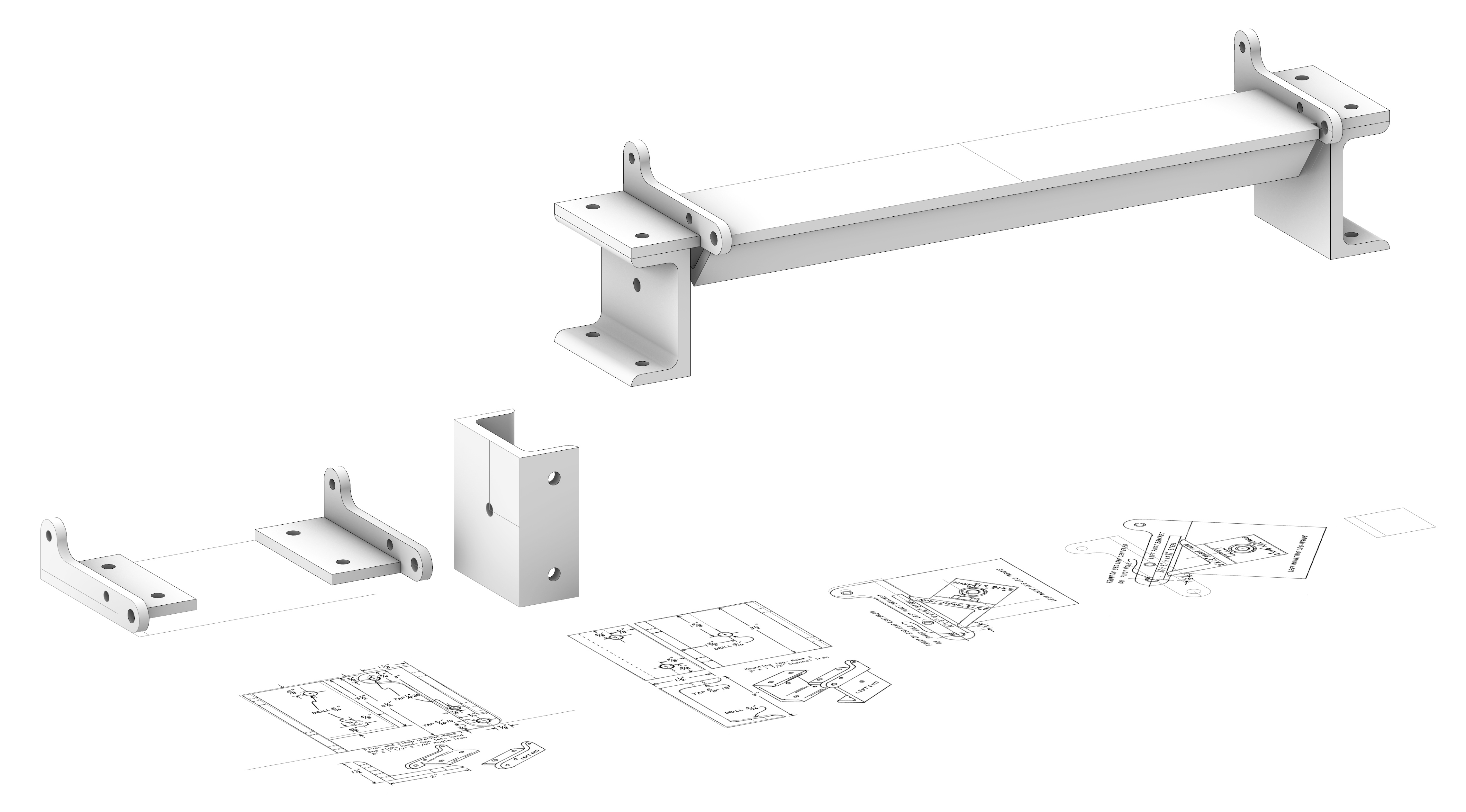 Fig. 1-4. CAD Process
To build the preliminary CAD model, I brought screenshots of the book into Rhino, scaled according to the dimensions, then
drafted the 3D parts. Some parts, such as the Bed Leaf, are not illustrated, but verbally specified.
 Fig. 1-5. CAD Process
To build the preliminary CAD model, I brought screenshots of the book into Rhino, scaled according to the dimensions, then
drafted the 3D parts. Some parts, such as the Bending Leaf, are not fully illustrated, but verbally specified.
Building the digital recreation, several of the design decisions rely on metal fabrication techniques.
- Much of the design uses standard metal angles and c-profiles for structural rigidity.
- Certain clearances in the design rely on tapping threads into the steel.
- Certain joints between the elements rely on welding.
For a rapid prototyping process, my first thought is to revise the design to use more sheet materials rather than angles,
so that I can make use of the lasercutter. 0.345" thickness acrylic is close to approximating the 3/8" steel stock used in the design.
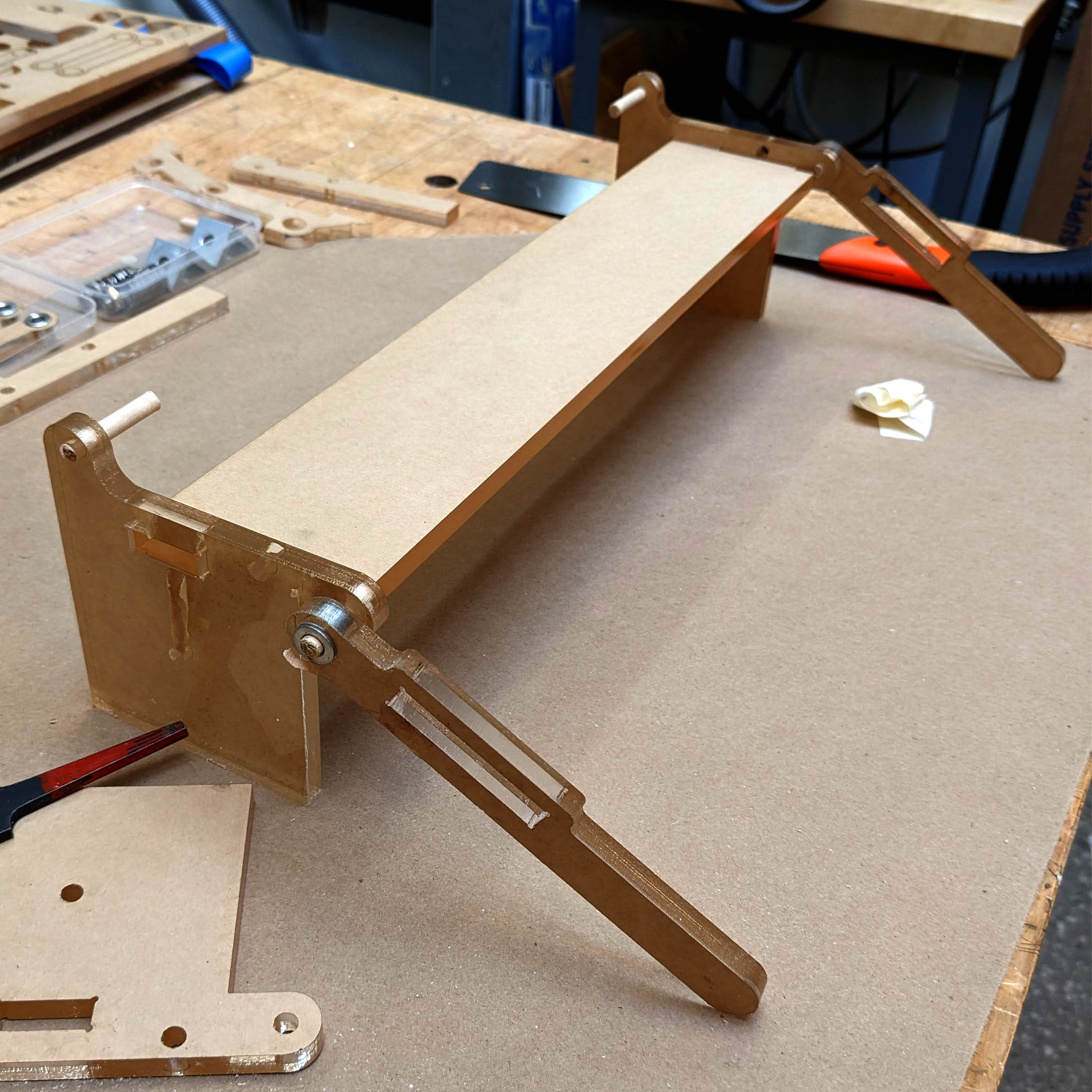 Fig. 1-8. For the joints, I used 0.25" wood dowels.
The design calls for specific 1/4" & 5/16" bolts at different places, but I was aiming for simplicity here.
Instead of bolts, I used friction-fit dowel joints in places which were meant to be threaded inserts.
In joints which were meant to have freedom to swivel, I used 0.25" ID aluminum standoffs friction-fit to sit in the acrylic.
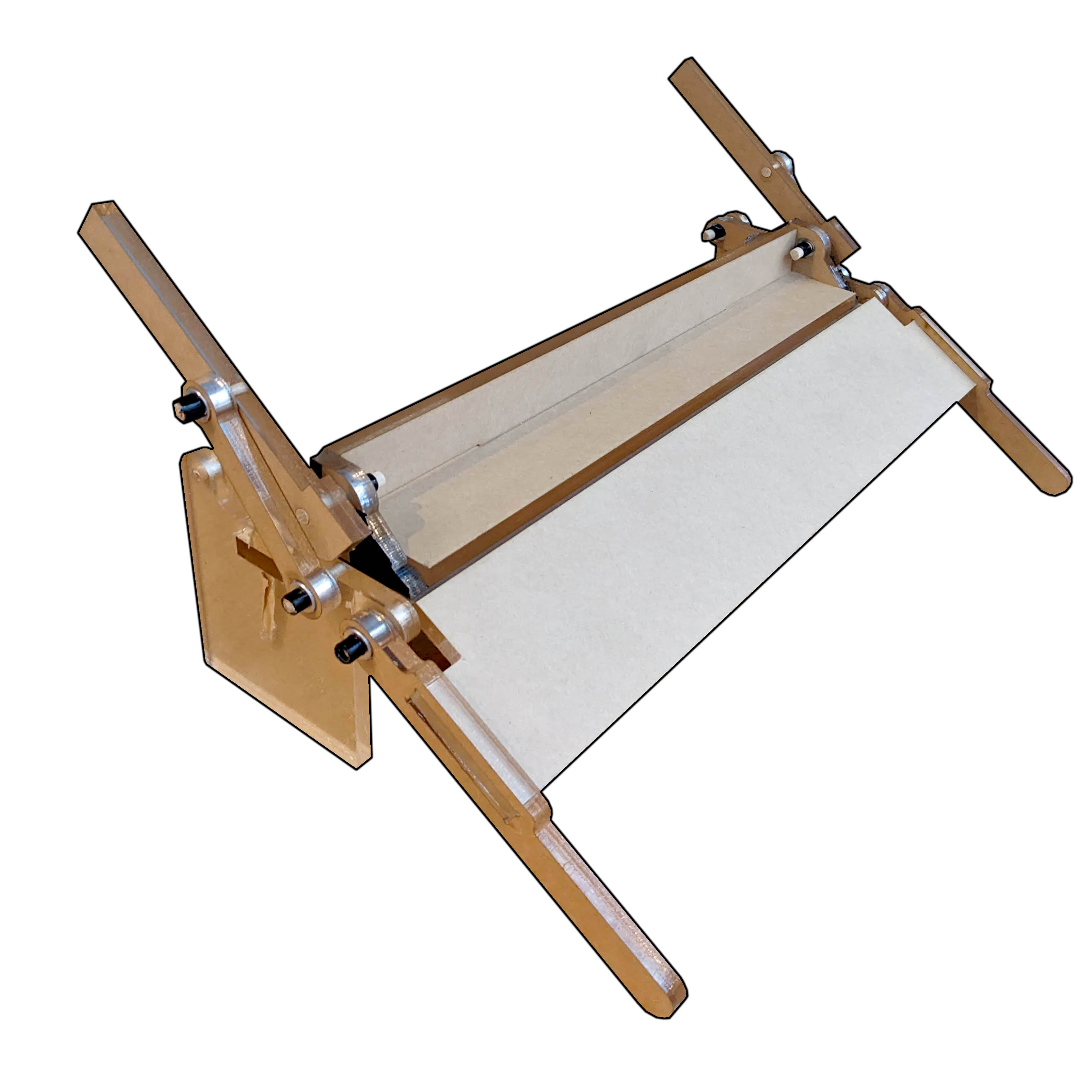 Fig. 1-9. Prototype V0 Assembly.
The design calls for specific 1/4" & 5/16" bolts at different places, but I was aiming for simplicity here.
Instead of bolts, I used friction-fit dowel joints in places which were meant to be threaded inserts.
In joints which were meant to have freedom to swivel, I used 0.25" ID aluminum standoffs friction-fit to sit in the acrylic.
In this situation, I would prefer to use Clamping Shaft Collars to limit motion of the acrylic links along the shafts,
but for this first prototype, I simply wrapped thin strips of duct-tape to simulate shaft collars.
In my efforts to translate the design from metal profiles to sheet materials,
I neglected the part where it should clamp to the edge of a table. Therefore, this
prototype is quite clumsy to use because you need to brace it with your spare hand.
This prototype emphasizes the need for a way to adjust the position of the clamp relative to the pivot position,
because the initial design is for 1/32" sheet metal, the clamp is too far back for me to even bend a piece of paper.
The original design has a 30" bed, and for saving material, I truncated the bed to 15" wide. However, the prototype feels
quite small, and I actually think that the wider bed will give it a better form factor.
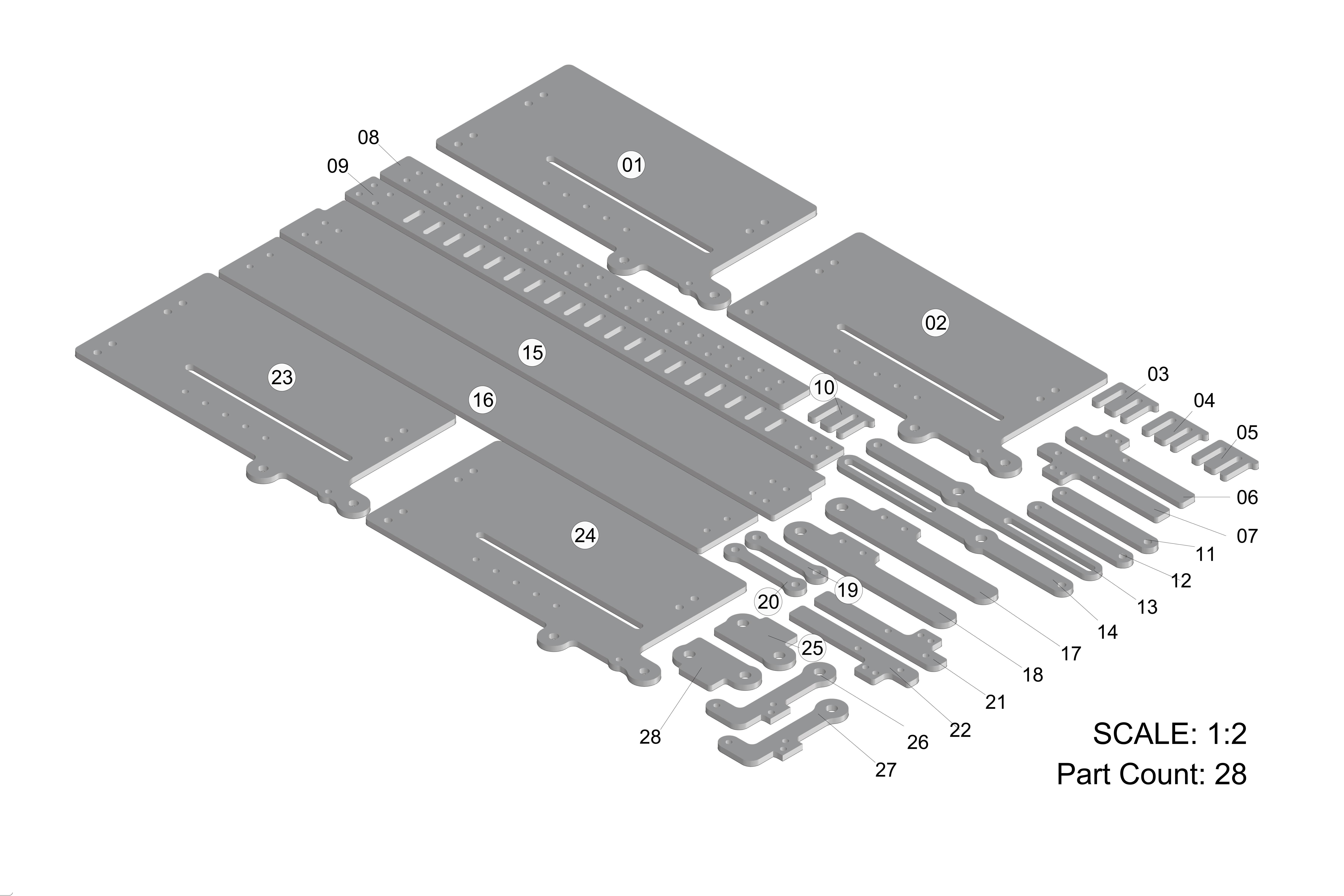 Fig. 1-11. 1/4" Steel Part Tracking
In addition to sending .dxf files to Xometry, I also sent accompanying documentation to make sure
the receiver was keeping track of the number of parts.
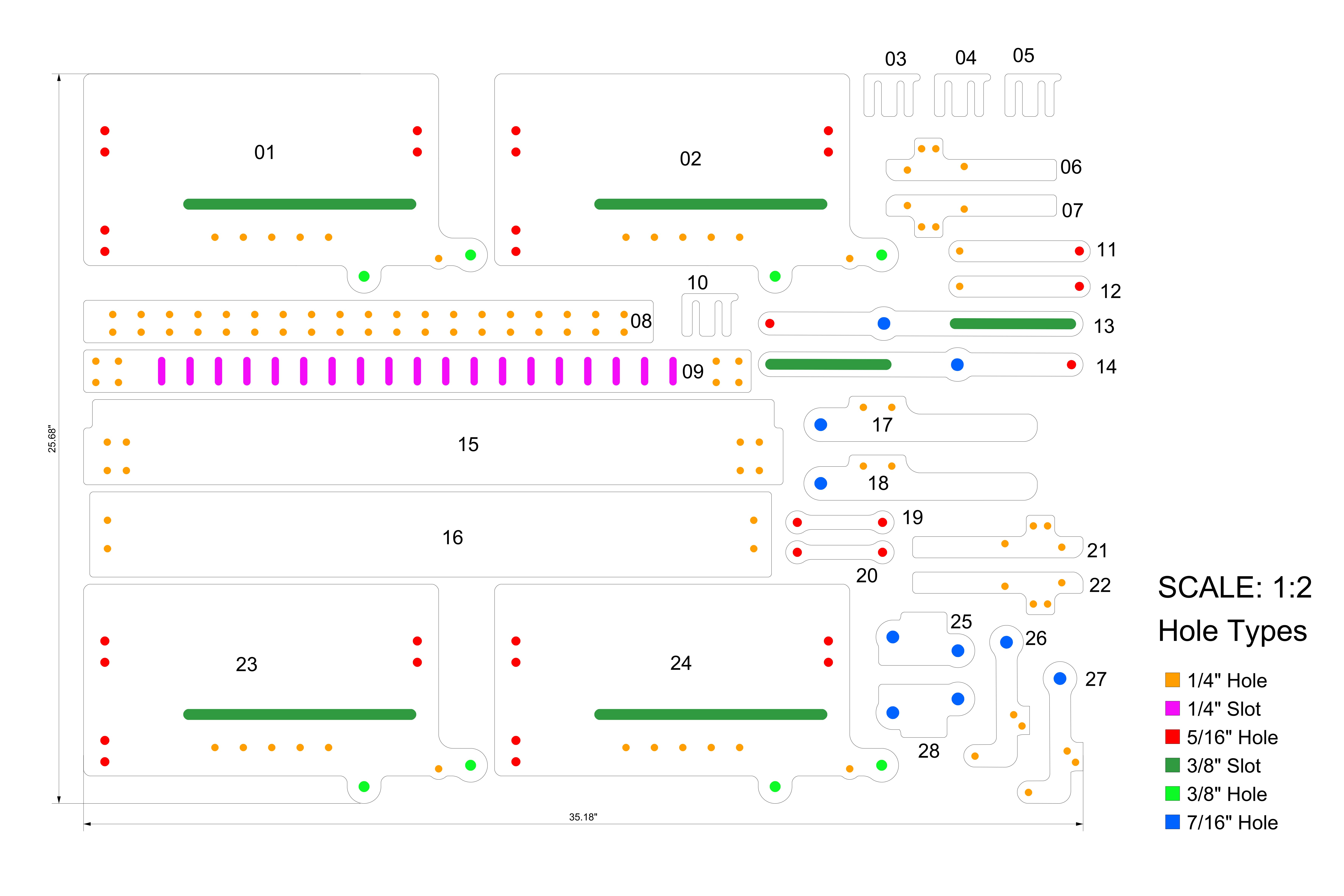 Fig. 1-12. Hole & Slot Schedule
Preparing a diagram of holes and slots was part of my own quality control process to make sure I've accounted for
all of the correct hardware as I prepare material orders.
Wherever possible in the design, I wanted to avoid using steel. Certainly the stiffness would be better for metal folding,
but it's much more forgiving to work with aluminum, especially as I'm anticipating there will need to be many modifications
as I progress through building the machine. The process begins by preparing paper templates, and taking my stack of
off-the-shelf aluminum profiles to N51 shops, where I can use the tools designated for working with metal.