Displacement Micrometry
- Magnetic encoders
- Optical reflective encoders
- Interferometry-based high-precision displacement measurement
- Displacement Measurement using an interferometer
Magnetic encoders
Magnetic encoders are the mosty commonly used sensors in the medium to high-precision range of displacament measurement. This is owing to thei low price, space-efficiency and ease of installation.
Magnetic encoders utilize a scale or tape that has magnetic domains linearly aligned in a specific pattern. Most commonly the changes between magnetic field domains are discrete, thus representing binary data. Advancement in materials science have also enabled continuous variations in magnetic field strength, thus offering an analog response. The read-head of a magnetic encoder contains magnetic field sensors, such as Hall effect sensors, magneto-resistive (MR) sensors, or inductive sensors. As the magnetic scale moves relative to the reading head (due to the linear motion of the object being measured), the sensors detect changes in the magnetic field pattern. These changes are output as an electrical signal and can be read out for example by a micro-processor.
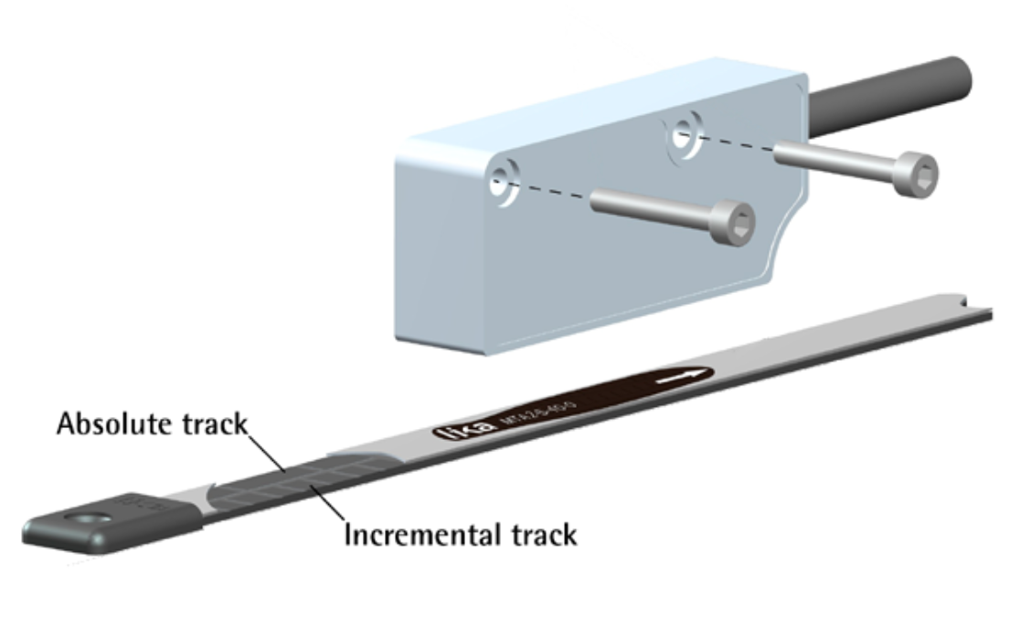
Source: https://www.likausa.com/news/sma2-absolute-magnetic-linear-encoder-precision-and-performance-perfected/
Accuracy: The resolution of magnetic encoders depends on the density of the magnetic domains on the scale and the sensitivity of the sensors. While high resolutions are achievable, magnetic encoders might offer slightly lower resolution and accuracy compared to high-end optical encoders, as discussed below, due to the nature of magnetic field interactions and sensor limitations. Typical magnetic domain densities on lower-end magnetic encoders are on the order 1 to 100 per millimeter, corresponding to a domain spacing of 5um. More advanced systems can, however, achieve sub-micron resolution.
Challenges:
- Magnetic Interference: External magnetic fields or materials that affect magnetic fields can interfere with the accuracy of magnetic encoders.
- Thermal Effects: Temperature changes can affect the magnetic properties of the scale and the sensitivity of sensors, potentially leading to variations in accuracy.
Cost: Low-end read-heads cost on the order of $50-100 while high-end solutions can be $500 or more. Magnetic encoder tapes range form $10-100 depending on quality and magnetic field profile.
Optical reflective encoders
Optical reflective encoder systems are widely used in high-precision displacement measurement. At its core an optical reflector is simply one or two LEDs that shine light on a micrometer grating of alternating reflective/transmissive stripes, the reflection pattern of which is then detected by a photodiode on the encoder. The obtained electrical signal is a sinuisoid with each cycle corresponding to the grating’s spacing.
One big advantage of reflective encoder is that they require very few components and are extremely space-efficient. The encoder readhead only measures few mm in with and length and about 1mm in thickness.
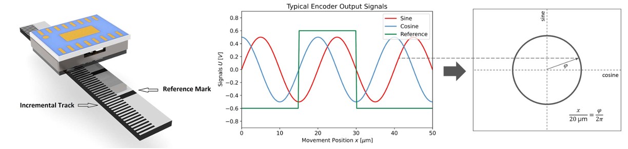
Source: https://www.smaract.com/en/metirio-key-features
SmarAct has a nice video showing how a reflective works.
Accuracy: Measurement accuracy (assuming good alignment, precise grating etc.) is limited by the line spacing and the signal processing of the resulting analog signal. Reading this out with a micro-processor essentially limits the achievable accuracy to number of bits of its ADC. For the example of this reflective encoder readhead by Broadcom (which I purchased from Digikey) the line spacing is 65um. It has a 12-bit ADC meaning the thoeretically achievable precision is 65um/4096 = 16nm.
Challenges:
- Dust!
- Alignment of readhead and grating.
- Imprecision in z-height of stage.
Cost: The Broadcom encoder readhead above cost $45. SmarActs encoders are $150 but claim <1nm resolution. Gratings are also on the order of $150, or can be made very easily with any lithography system and an evaporator. Fully integrated systems from manufacturers cost multiple thousand dollars.
Interferometry-based high-precision displacement measurement
Interferometry-based displacement measurement is, amongst the techniques discussed here, the one with the highest precision. Due to its high-sensitivity it is, however, also highly challenging to implement without very costly, high-precision components. Lithography direct-write machines like the Heidelberg MLA use two sets of interformeters for the motion feedback-loop in x- and y-direction.
Interferometry exploits light-interference to achieve nanometer-scale accuracy. It involves the superposition of two or more light waves to observe the resulting interference pattern, which can be analyzed to determine various properties of the light sources or the mediums through which the light has traveled. When applied to displacement measurement, interferometry can detect incredibly small changes in position, making it an invaluable metrology technique for applications where highest precision is needed. The most well-known geometry is the Michelson interferometer, developed by Albert A. Michelson in the 1880’s.
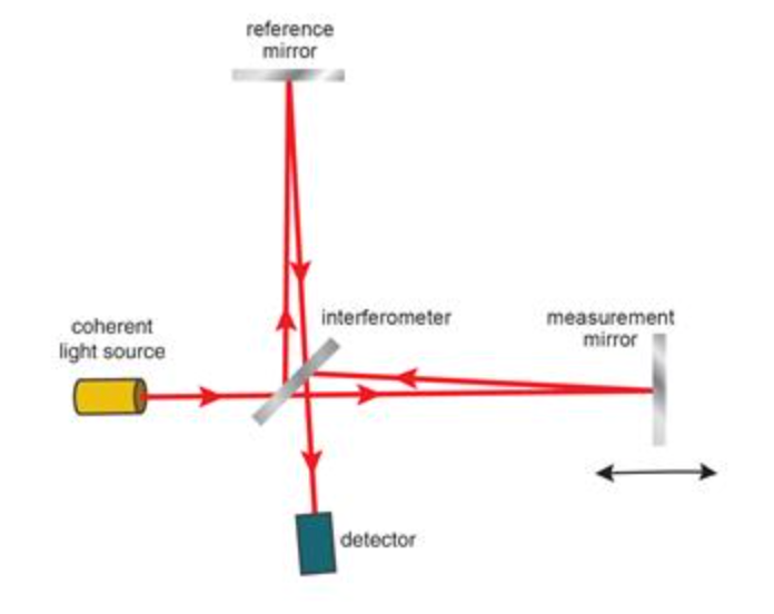
Source: https://www.renishaw.com/en/interferometry-explained–7854
To ensure measurements with distinct fringes, the use of a coherent light source with a single highly-stable wavelength is required. For this typically a laser is employed to create a superpoistion of two light beams. This is achieved by palcing a beam-splitter in the center between two mirrors. This splits the incoming light into two beams with different optical paths. These two beams are then reflected back and superposed at the measurement mirror. Here, an interference pattern is formed in the shape of concentric (for a well-aligned setup) fringes. So how can we use this for displacement measurement?
Displacement Measurement using an interferometer
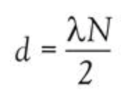
Path Length Sensitivity: When one of the mirrors in an interferometer setup is moved, even by a fraction of a wavelength of the light being used, it changes the path length of the light beam. This change in path length alters the interference pattern.
Quantifying Displacement: By counting the number of fringes that move across a detector as the mirror is moved, and knowing the wavelength of the light, one can calculate the displacement of the mirror with high precision. Essentially, each fringe shift corresponds to a displacement of half the wavelength of the light used, due to the wave nature of light and the requirement for a path difference change of one wavelength to move from one fringe to the next.
You can see it in action here.
Challenges:
- Alignement has to be extremely precise to obtain concentric and clear fringes.
- Vibrations: Even the slightest vibrations (for exmaple from stage motors) can cause sufficient distortion to make fringes undetectable. The Heidelberg MLA uses an air-bearing driven stage for this reason.
- Dependency of light wavelength on exact refractive index of the air it is in, influenced by humidity, temperature, and pressure. Poor environmental control is one of the most common factors for poor alignment in lithography runs.
Cost: Not considering measures needed to reduce vibrations such as the stage and dampened table, an interometer can be assembled at a cost of about $500 or less (mostly depending on quality of lenses and mirrors used).