Make sure the electric circuit is complete before you "probe" the milling machine to calibrate it. If you don't, you will break the drill.
Week 06
Electronics production
Tools: Genmitsu milling machine, Autodesk Fusion 360 for board design, Universal Gcode Platform (Version 2.0.20) to send the gcode file to the milling machine, Quentin's online gerber to image tool, and Professor Neil's modsproject online tool to create a gcode file.
Previous experience: none
So, what exactly did I do this week?
This week can be broken down into three distinct stages:- creating a board design and file to send to the milling machine
- milling the board
- soldering components on to the board
PCB design and file exporting
I used the software tool "Autodesk Fusion 360" to design a board with 3 button, 3 resistors, and 3 LEDs. I used the "Change" icon to update the
trace width to 16mm. This is an important step to ensure that the board is feasible - in other words, so the milling machine and 1/64" drill can actually make the board
design.
I then went to the “Manufacturing” tab and clicked the button “Export Gerber”
I went to Quentin's online gerber to image tool, where I clicked and dragged the following gerber files: “profile.gbr”,
then lock the origin and dimensions to save the desired size, then “copper_top.gbr”. I clicked the check box for “black and white”
I then downloaded the render and saved the file as a .png file. I then clicked and dragged the file "copper_top.gbr" to the tool and saved a black
and white file of the edges which I'd use later in the milling machine.
Then I went to to Neil’s cool modsproject online tool. I right clicked, went to “program”, “open program”, "Machines", "G-code", “Mill 2D PCB”. See the screen grab below for these steps.
On the bottom left, I clicked “Select PNG File” and uploaded my board file. I clicked “mill traces (1/64)”. I made sure the cut depth and max depth is 0.1 mm - the milling machine likes this.
I clicked calculate - this will create and prompt you to save a .nc file (which is the same as a gcode file).
I followed the same steps as above for the board outline. I used the “profile.gbr” file on Quentin’s tool, uploaded that to Neil’s tool, and clicked on “Mill Outline (1/32)” instead of “Mill Traces (1/64)”.
Now I have the files I need to move to the milling machine!
PCB milling machine
In room 043 of building E15, I used the desktop connected to the Genmitsu milling machine to upload my .nc file from Neil's online tool.
I used the program “Universal Gcode Platform (Version 2.0.20)”. I opened my .nc file that included my traces.
I used the arrow icons to move the milling machine around until I was towards the bottom left of the fresh board, then I pressed the “X0” and “Y0” buttons to set my x-y axis.
I made sure the 1/64” milling tool was equipped on the milling machine.
I went to the “Macros” tab on the software, and clicked the icon on the right named “[2] Probe and zero Z” to calibrate the machine for the board I have installed with my 1/64” milling tool.
The machine got angry at me because I had not correctly setup the grounding wires. I had to position the top wire with a magnetic clip on to the top of the milling machine.
The milling machine then calibrated itself for the z position.
I then turned the vacuum on.
I sent the file to the machine by pressing the “play” button.
Then the milling machine got to work! It drilled a thin layer of copper off the top of the board in the shape that was defined by the gcode file. It took about 10 minutes to complete.
The final milled part came out really well!
Then I moved on to the outline portion, and things went poorly. I uploaded my outline .nc file so I could now mill the edge of the board. The upload went fine, and the file looked good on the software package.
I raised the milling tool so I could swap out the 1/64 drill with the 1/32” drill. Then I was unsure what to do next. I was trying to position the drill so I could calibrate the z-scale of the machine,
but I had an “ALARM” error which was preventing me from changing any parameters. After looking around a while, I decided to click the “home” icon, which then sent the drill to the top right position.
I then used the arrow icons and moved the drill to the bottom left, close to where I thought I was before, and then ran the “[2] Probe and zero Z” macro to calibrate the machine.
However, this time the machine kept pressing down until the tip of the 1/32” drill snapped off! I have no idea how this happened. I was expecting the machine to be smart enough to stop itself and calibrate accordingly.
I moved the drill back to the “home” base so I could raise it and remove the broken drill. I put a new drill in, moved the drill back to an x and y position I thought was similar to before.
I then realized I did not have the grounding wire connected to the top of the milling machine. That is why when I tried to probe and zero Z before, it did not register a connection with the copper top and kept pushing. I replaced the grounding wire in the correct position and tried again. This time it probed and zeroed beautifully!
However, now I am not sure what x and y coordinates the tool and the software are using. I have the edge file uploaded, but if I hit run, will it run along the correct edge?
In other words, does it remember where I traced my previous outline? I decided to try, so I pressed “play” and watched closely so I could stop the run if if it went off track. This did not work.
The milling tool created an edge that went directly through my previous piece. I let it run to completion so I would have a board to practice soldering on, but it will not be my final piece.
I reran all the steps above. This time, I made sure to maintain my xy base position during the entire process. I printed a complete board with the right edge parameters! See a nice image below.
Soldering my new board
In room 043 of building E15 I used the soldering equipment and CHIPQUIK 2.2% Flux Core Solder Wire to solder two buttons, a 1000 ohm resistor, a 10 ohm resistor, and 2 blue LEDs to my new board. I tested the 1000 ohm resistor track with a multi-meter and it worked well. I did not have time to check the 10 ohm resister track with a multi-meter, and assumed it would work normally.
I plugged in the new RP2040 microcontroller to my computer. The main LED was blinking brightly until I pressed and held the “B” button, then pressed and released “R” button, then released the “B” button.
This enabled me to see the RP2040 as an external drive on my computer. I then copied over the .uf2 file RPI_PICO-20230426-v1.20.0.uf2 to the RP2040 microcontroller.
Now I can talk to it via Thonny.
I wrote a simply program in micropython which turns off the on-board LEDs on the RP2040 and turns on pins 6 and 7, which are connected to the buttons and LEDs on my board.
I saved the program on the RP2040 microcontroller and ran it. This turned off the on-board LED lights. When I click the button with the 10 ohm resister, the blue LED turns on! However, when I click the button with the 1000 ohm resistor, nothing happens. I must have poorly soldered the components on this track. Testing the circuit with a multimeter would have identified this issue.
Images and videos
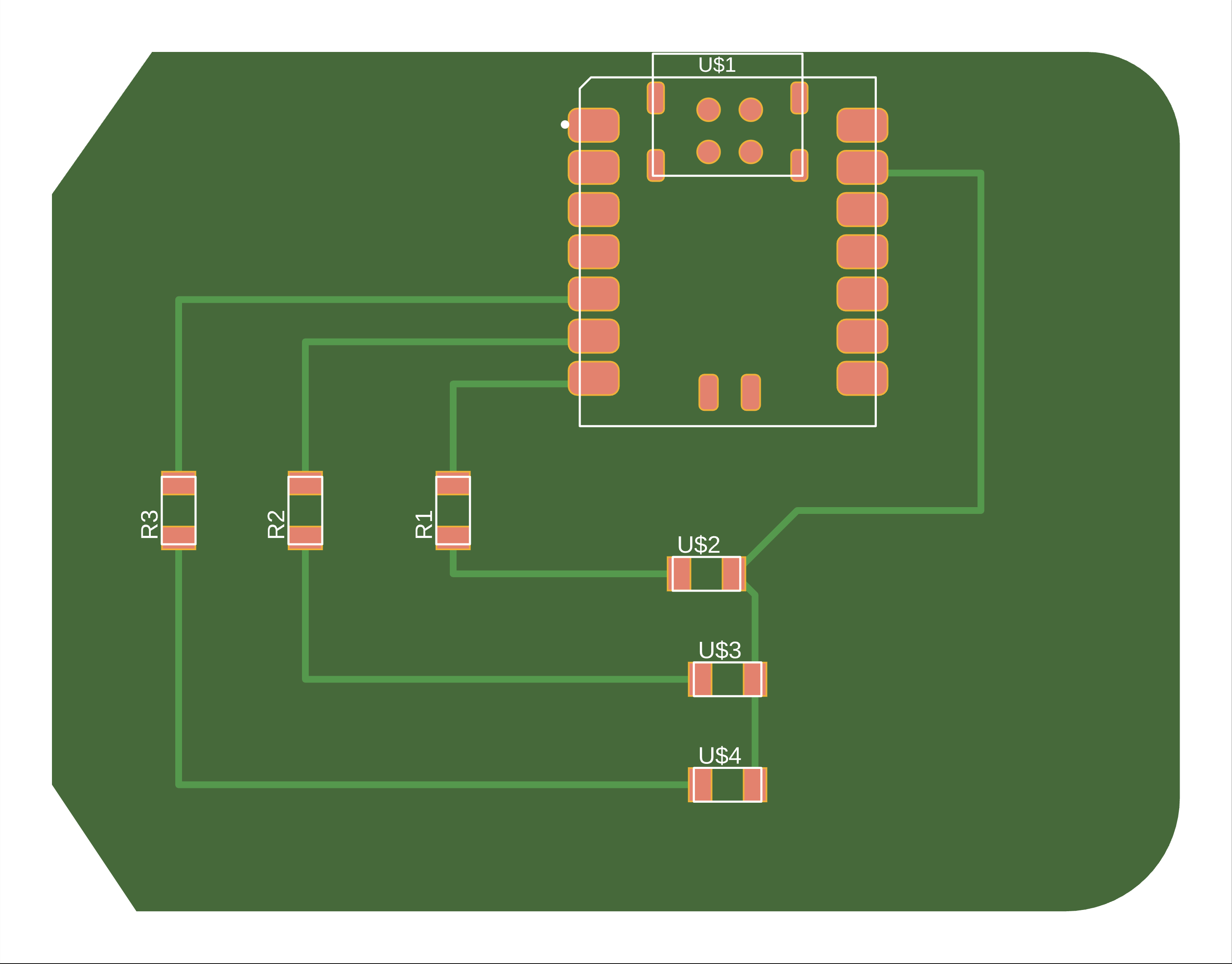
A png file of the first board design I made for the milling process
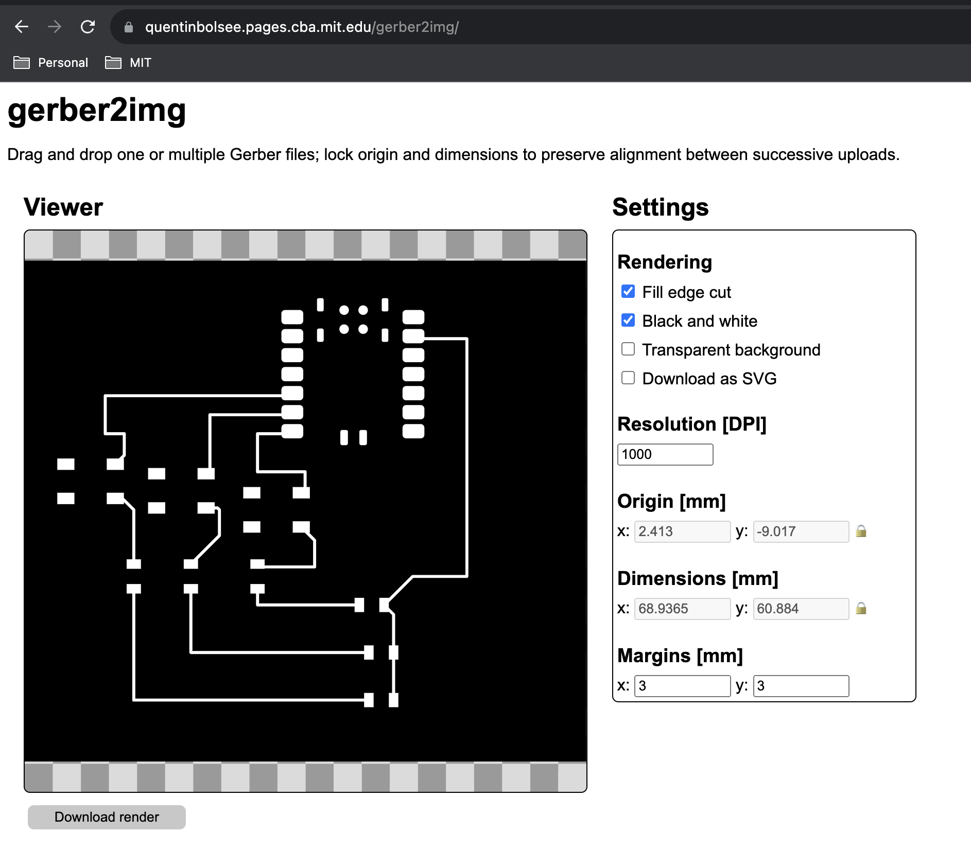
screenshot of Quentin's tool to create a black and white image file of the PCB
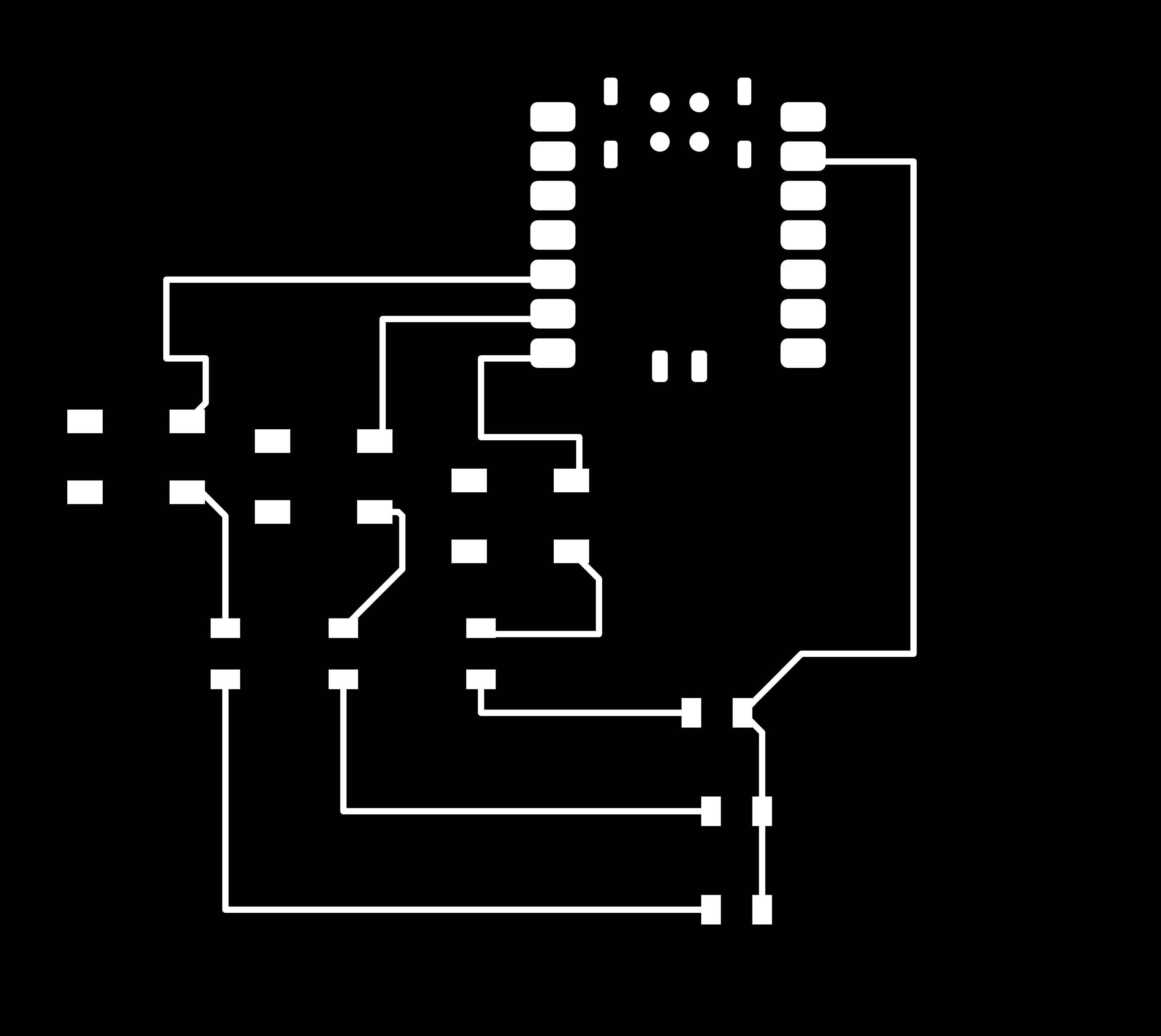
The final output of the black and white image
Step 1 of using Neil's online tool to create a .nc file
Step 2 of using Neil's online tool to create a .nc file
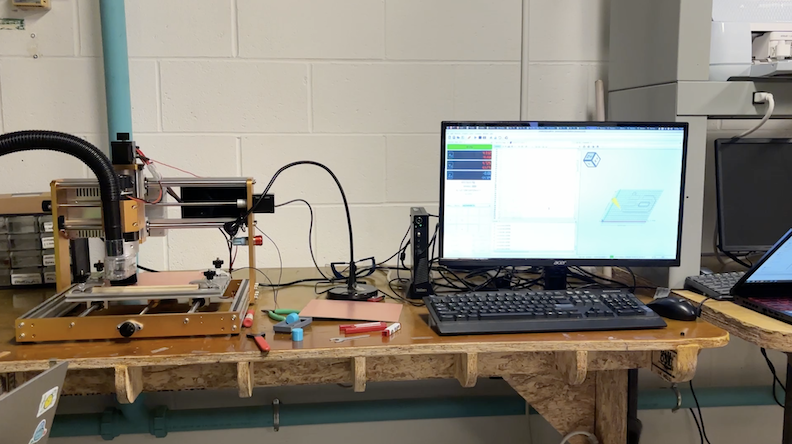
The milling machine!
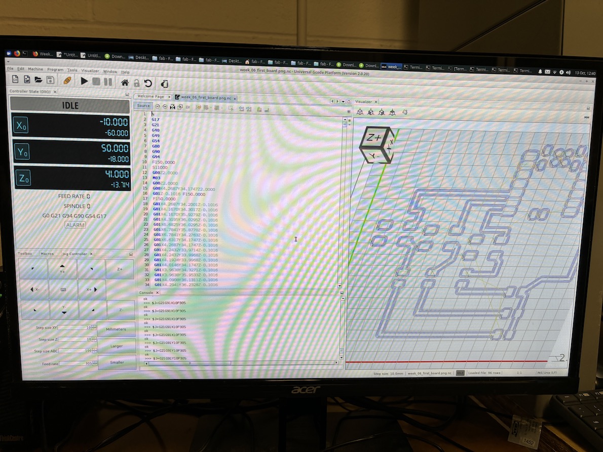
Using the universal program to send the gcode file to the milling machine
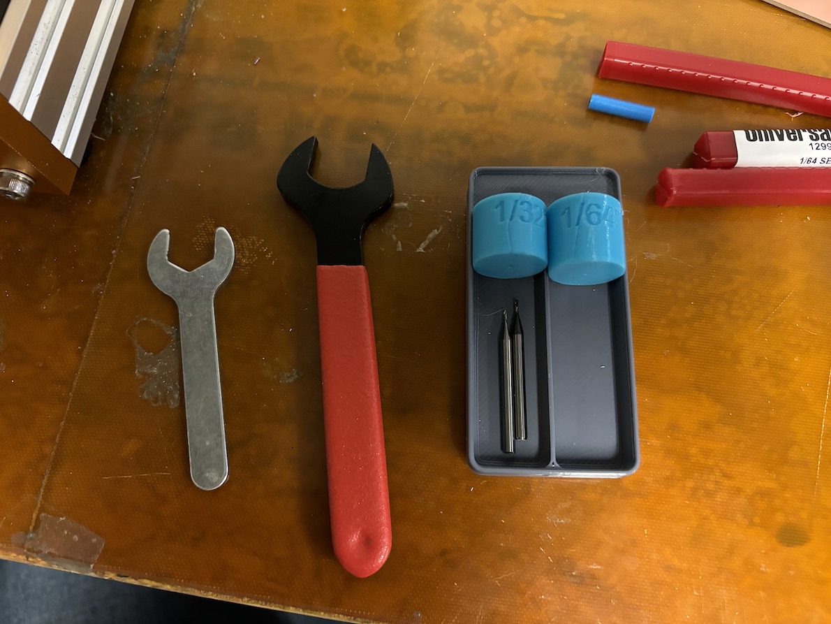
The tools used to change the drills on the milling machine. I used the 1/64" drill for the traces, and the 1/32" drill for the edge/outline.
Running the milling machine!
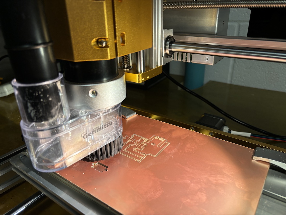
The milling machine is almost done making the traces of the board
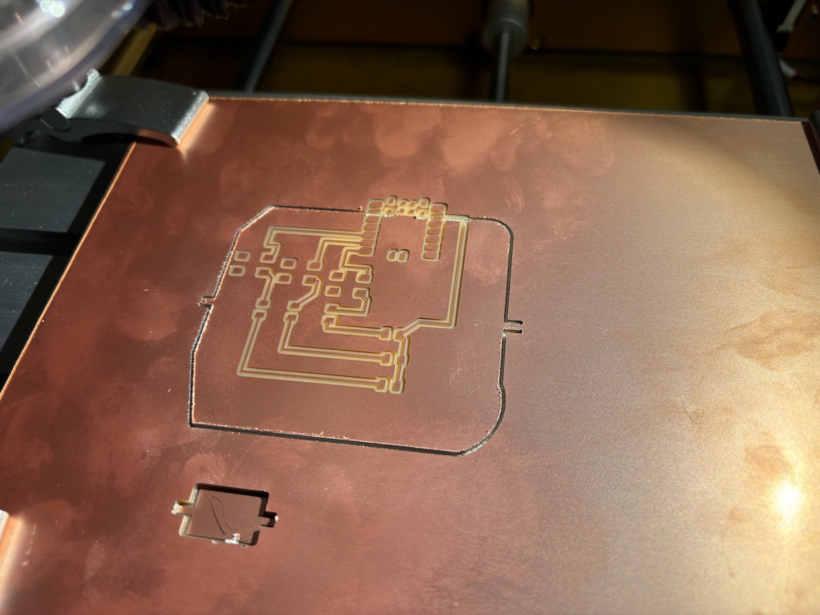
This is an image of my "bad" board where I lost my xy base and when the edge was milled, it was off position
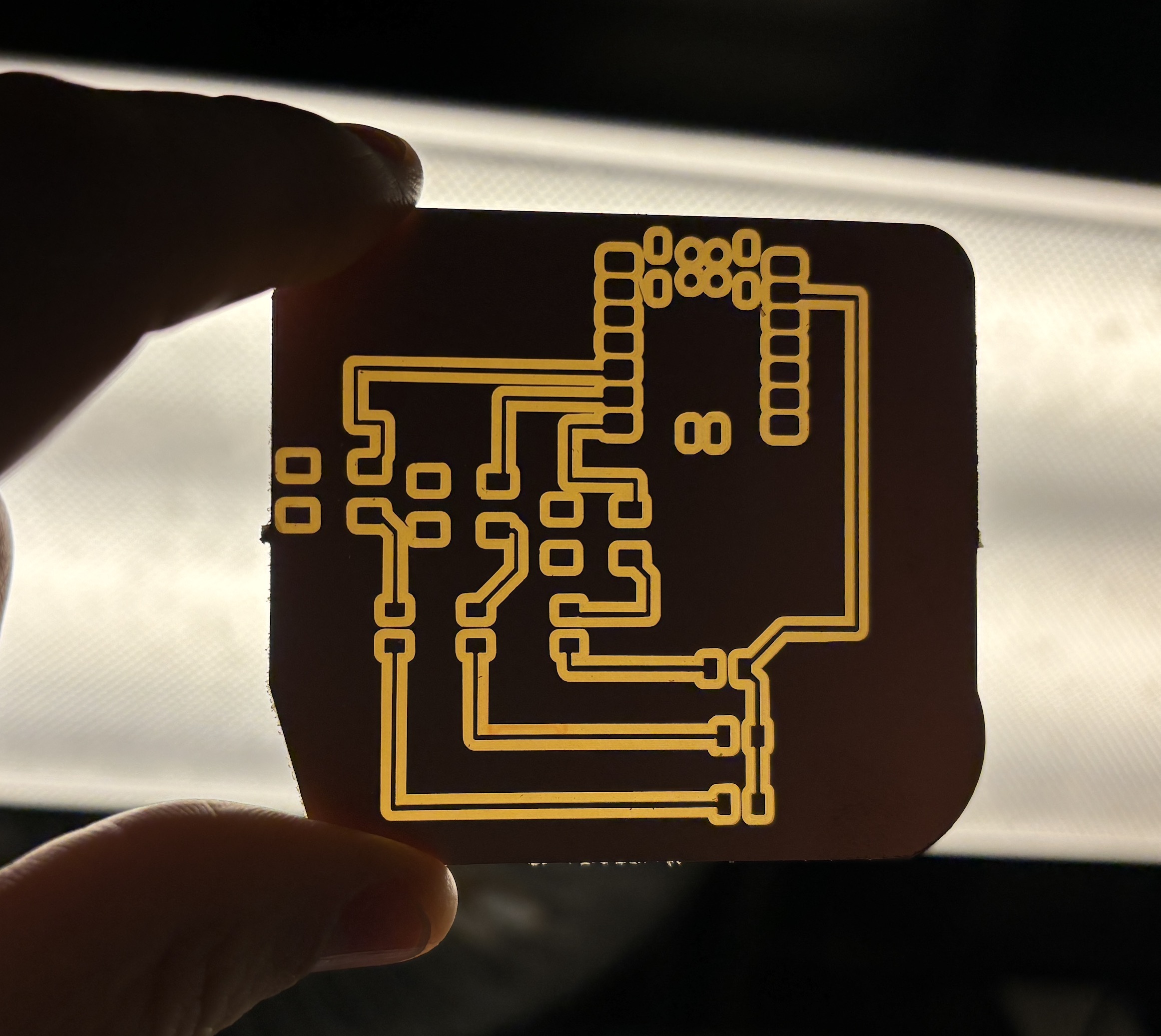
The final board held up to the light
First attempt at soldering a resistor on the board
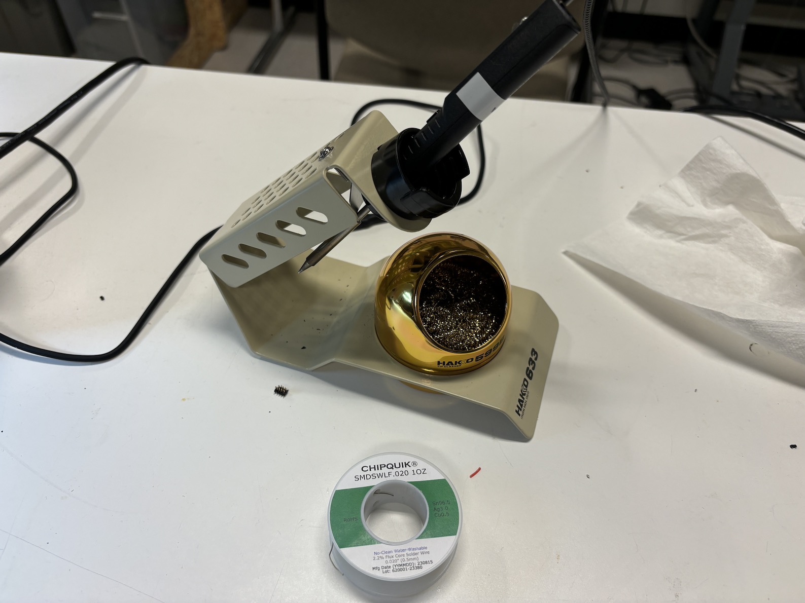
Soldering equipment used to add components to the new board
Using a multimeter to test the button, resistor, and LED connections
Video of new board with LED on when button is pressed