The EDS lab has incredible soldering tools!
Week 11
Networking and communications
Software Tools: Autodesk Fusion 360 (aka Autodesk Eagle), Thonny, Universal Gcode Platform (Version 2.0.20) to send the gcode file to the milling machine, Quentin's online gerber to image tool, and Professor Neil's modsproject online tool to create a gcode file.
Hardware Tools: Genmitsu milling machine, SD card reader/writer (CONN MICRO SD CARD PUSH-PULL R/A), Raspberry Pi Pico W microcontroller
Previous experience: Board design and soldering experience from previous weeks
This week can be broken down into three phases:
- Designing a board with an SD card reader and writer
- Milling the board and soldering the components on
- Communicating between the SD card and the microcontroller
Video running micropython code on the microcontroller to write to and read from the SD card.
I was also able to play a custom audio file from the microcontroller's local 2MB flash memory
Video of plugging in the microcontroller and playing a custom audio file.
Designing the board
Similar to the last two weeks, I needed some help this week. I referenced
Prof. Neil's board diagram
for inspiration on connecting an SD card reader to a microcontroller.
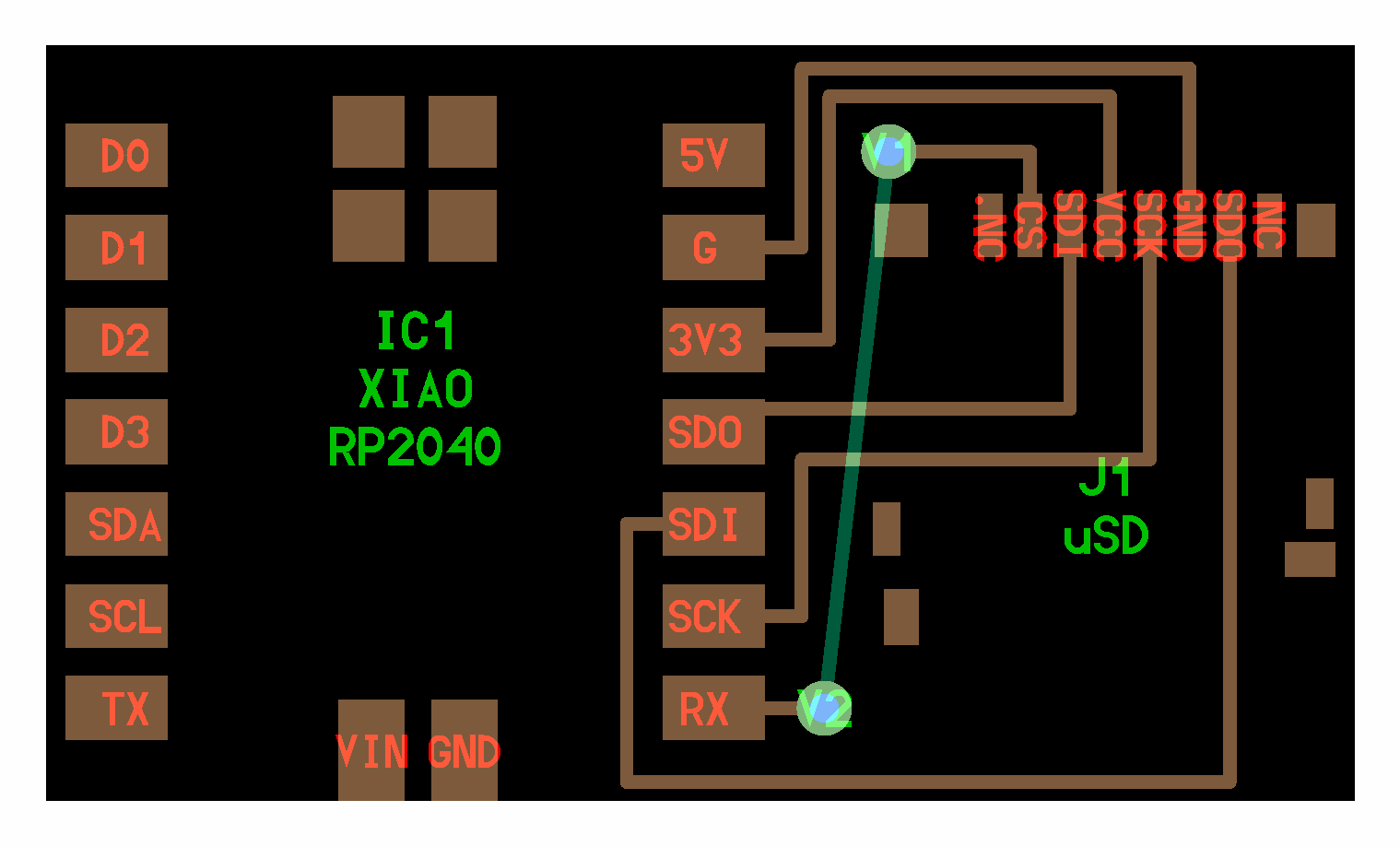
I created a schematic and PCD in Autodesk Fusion of the new board with a micro SD card reader/writer.
I used the CONN MICRO SD CARD PUSH-PULL R/A component from our inventory.
I followed the process I documented in Week 06 Electronics Production
to create the necessary IMG files and gcode files from the gerber files that I exported from Autodesk Fusion 360.
Here are the files I created for easy reference:
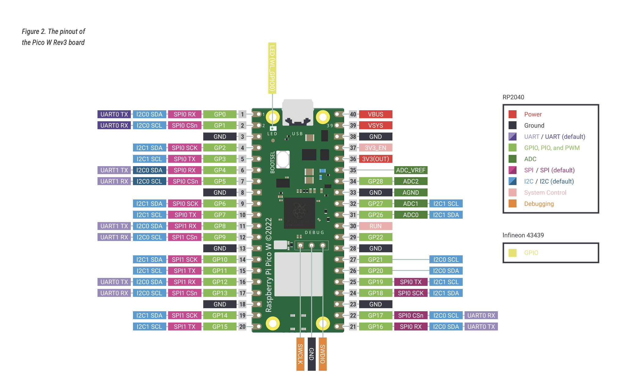
Screenshot from Raspberry Pi Pico W microcontroller datasheet
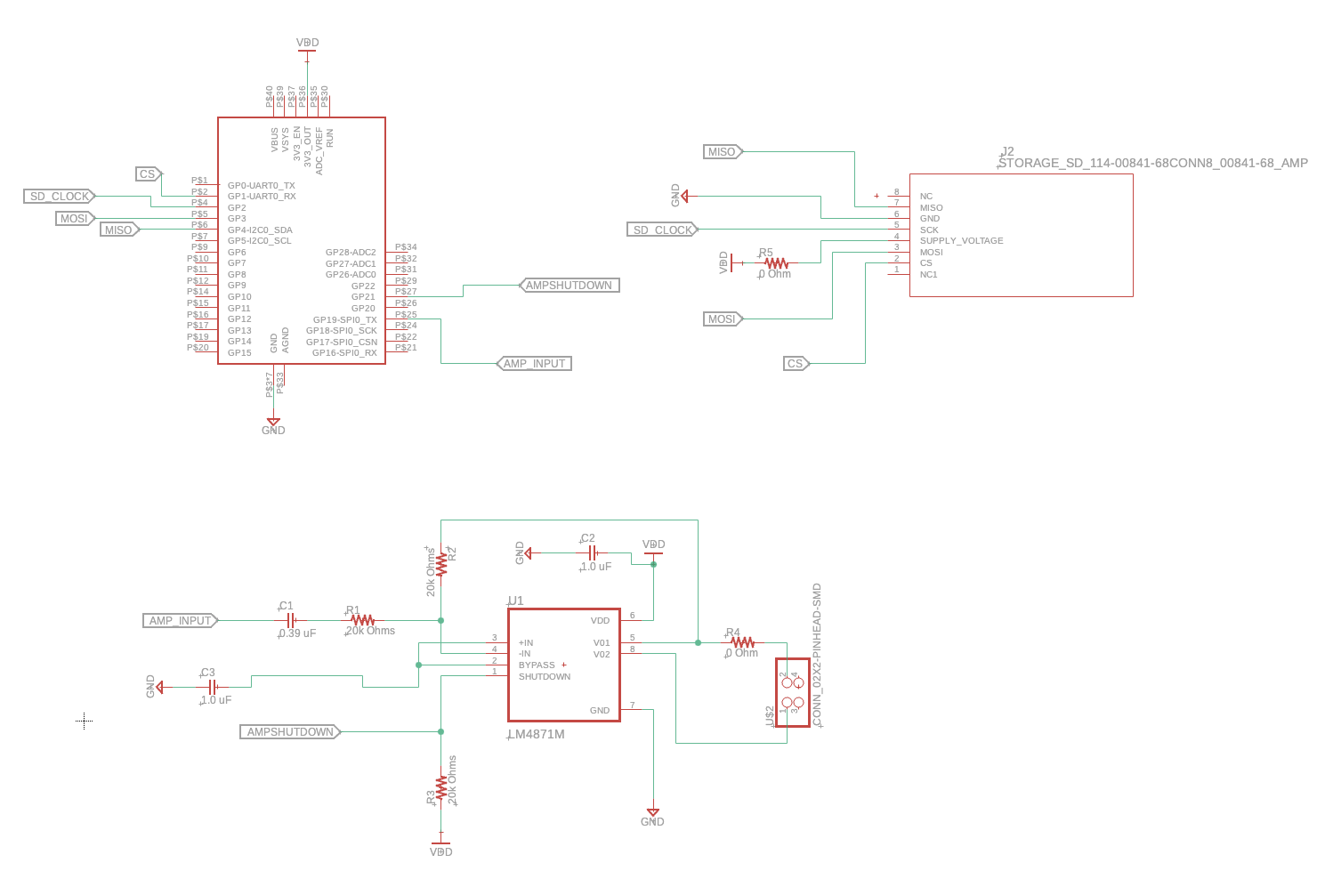
Screenshot of the board schematic
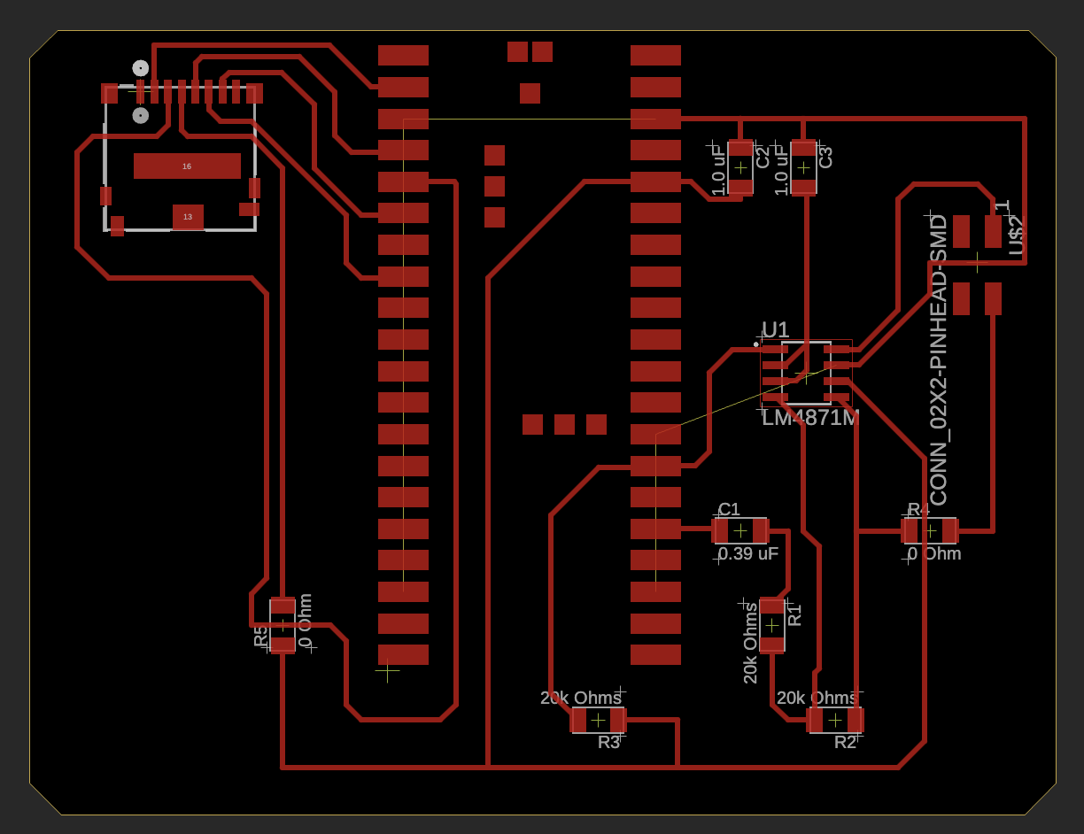
Screenshot of the PCB
Milling the board
I used the Genmitsu milling machine in E15-043 with the Universal Gcode Sender software on the adjacent desktop machine.
I followed the process I documented in Week 06 Electronics Production to
mill the board. There were unique challenges with the milling machine this week, however. See the challenges section below for more details.
If needed, this website has a good guide on how to use the "UGS platform".
These are the steps I followed to run the milling machine:
- Click “Open” - select my gcode file (.nc)
- Check if the drill is the right one (1/64” for traces, 1/32” for edge cutting)
- Click “macro” -> “[1] Raise Z”
- Setup the grounding cables, and click “macro” -> “[2] Probe and zero Z”
- Position the drill to the right position and set X0 and Y0
- Press the play button that reads “send” and start milling
- Turn on the vacuum cleaner and wear ear mufflers or noise-cancelling headphones
- Repeat the steps above for the edge of the board
Video of the milling machine running
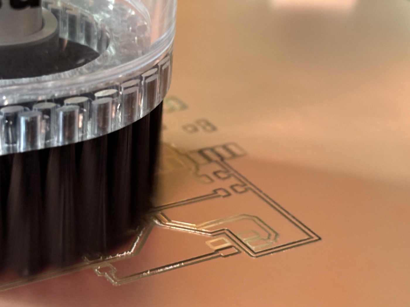
Picure of the first milling challenge I had - the mill did not reach the correct depth. More on this below.
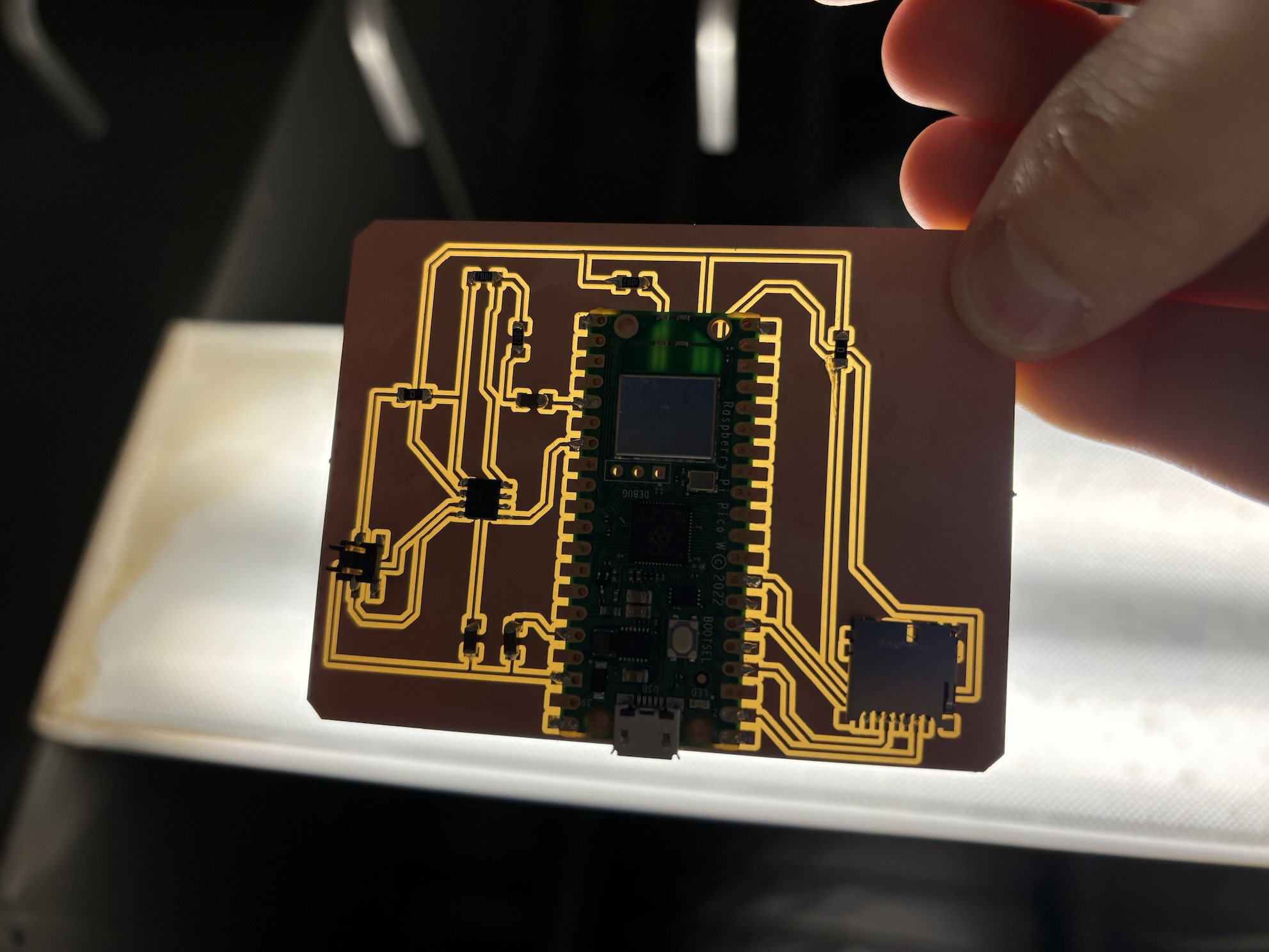
Picure of the final board held to the E15-043 light.
Soldering components to the board
Soldering this week was difficult. I think the soldering iron tips in E15-043 are old, damaged, or worn out. I struggled for hours to solder all the components on the board, especially the SD card reader/writer which has tiny pins. After struggling in the CBA shop, I decided to visit the EDS lab where I discovered an incredible soldering setup! Using the equipment there was much easier. For example, the soldering iron has a precise narrow tip which I could use to carefully solder the tiny pins of the SD card reader.
I used the following components for my board:
- Raspberry Pi Pico W microncontroller
- LM4871M amplifierlink to DigiKey
- Three 1.0 uF capacitors
- Three 10k Ohm resistors
- Two 0 Ohm resistors
- One 2x2 header
- One simple 4 ohm, 3 watt speaker from Amazon
- One CONN MICRO SD CARD PUSH-PULL R/A
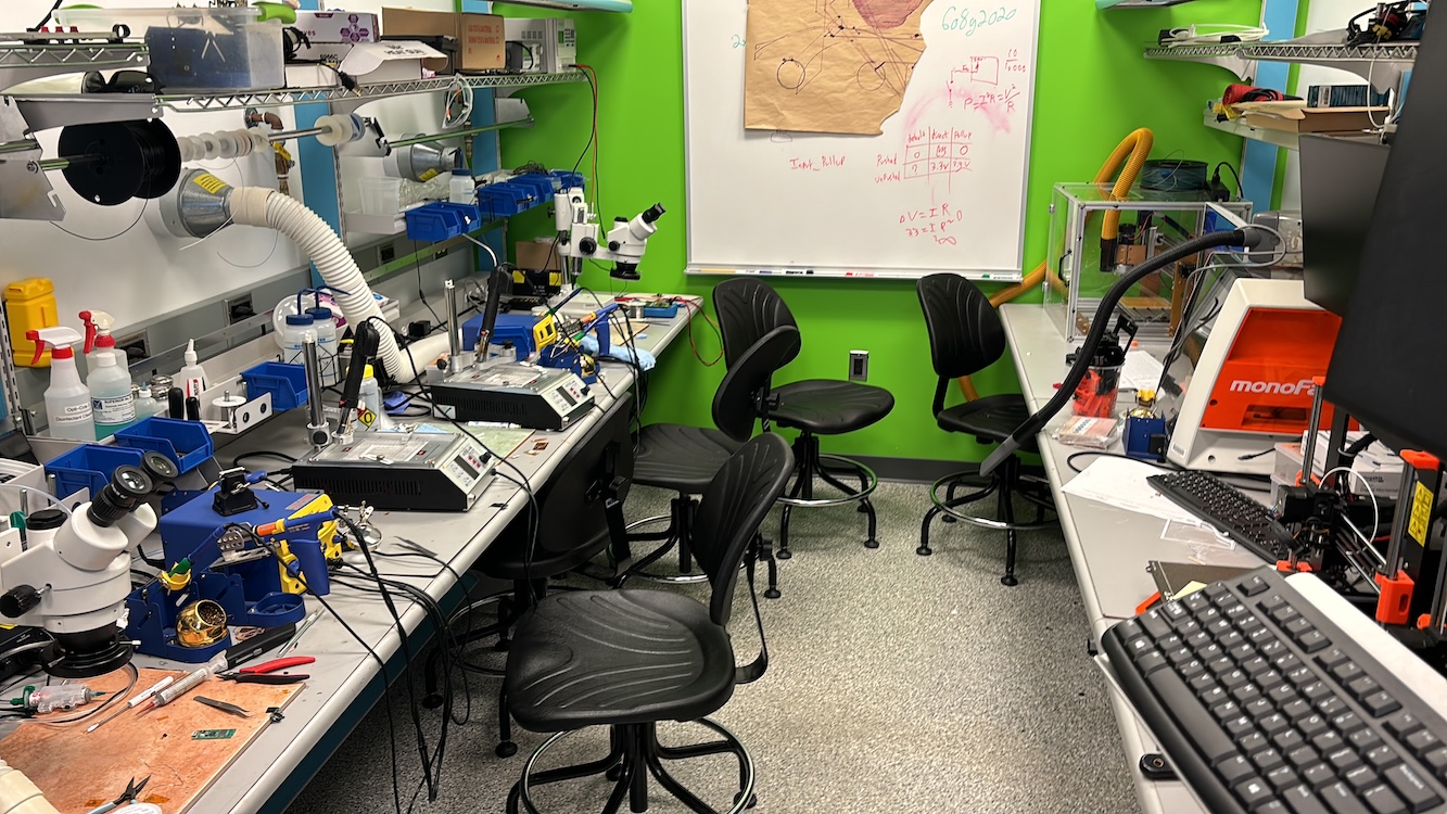
My new favorite room, the soldering stations at 38-051
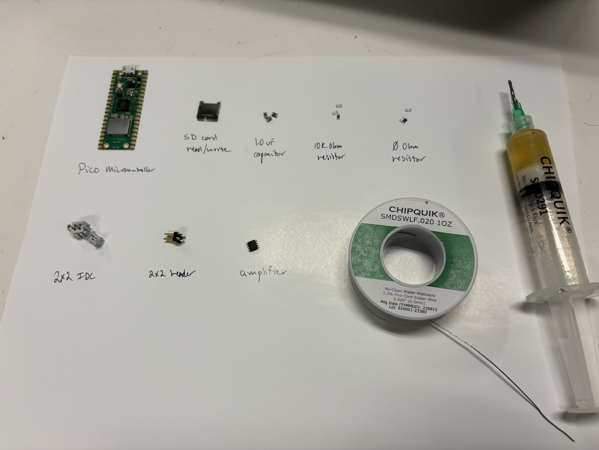
The components I used on the board
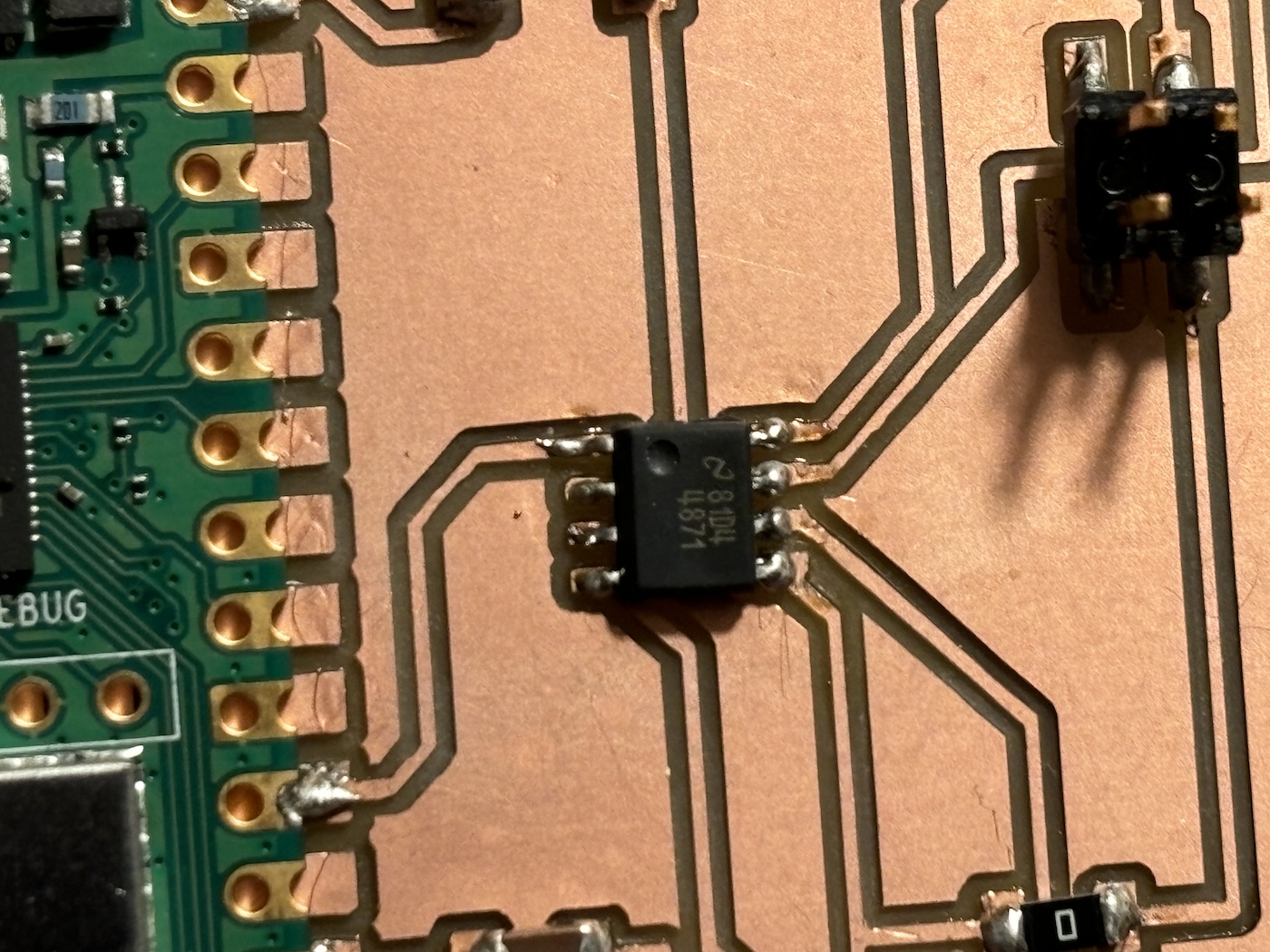
Amplifer on the board
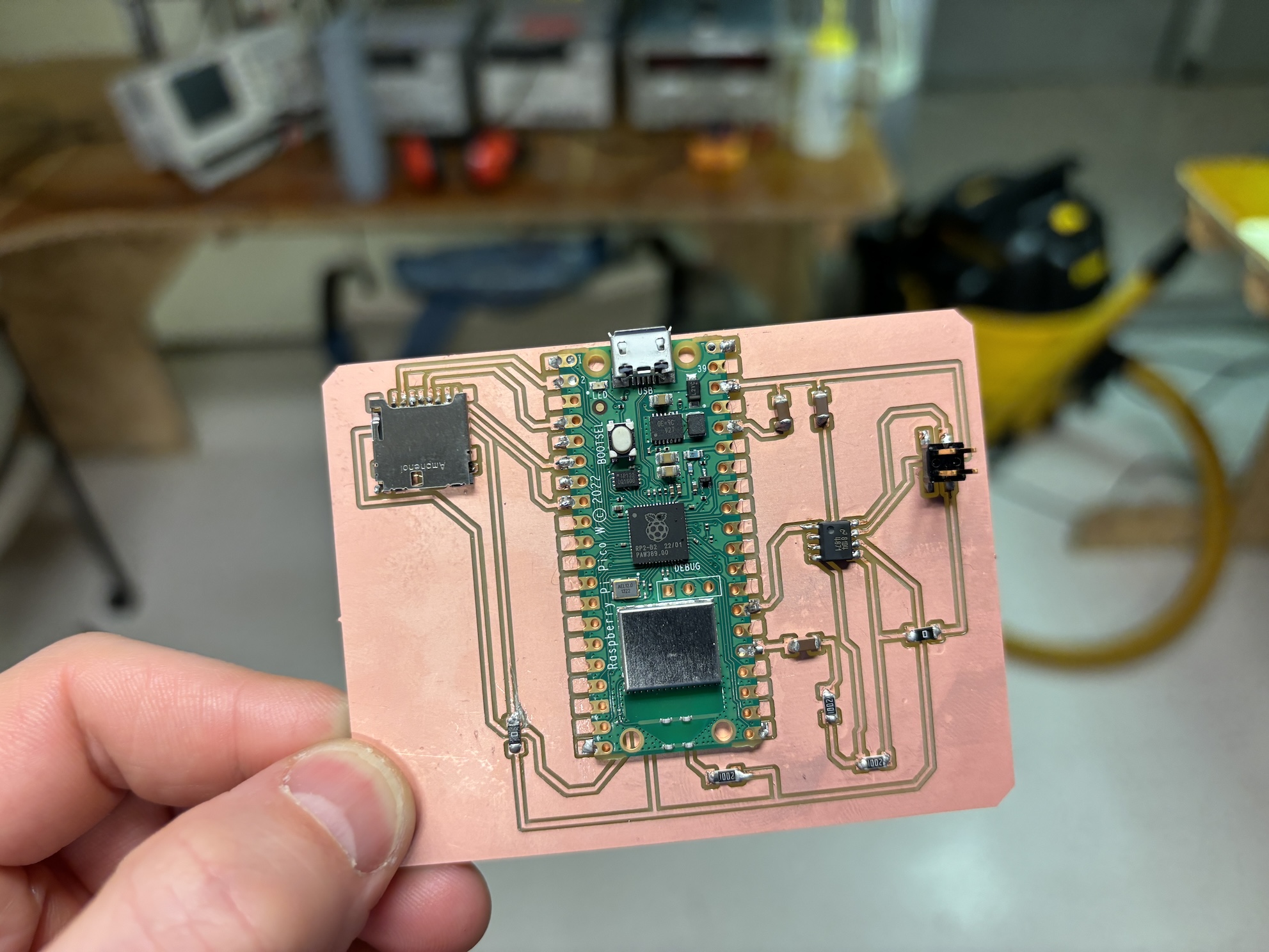
Final board
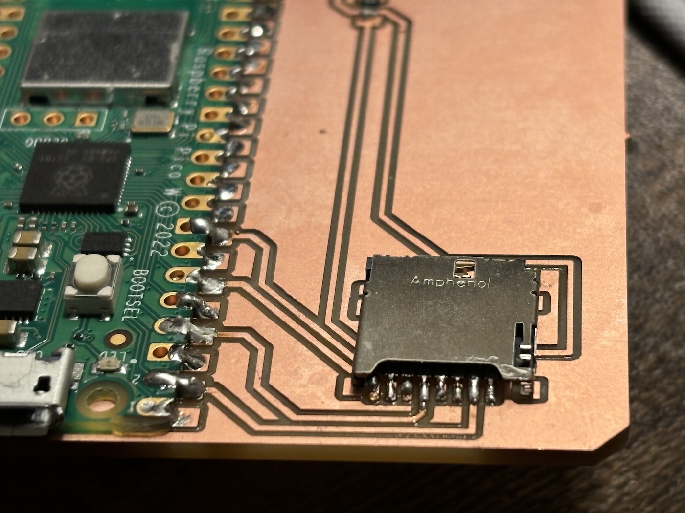
Final board with close up view of the SD card reader
Communicating between the microcontroller and SD card
First I setup Thonny with the Raspberry Pi Pico W microcontroller. Specifically, I did the following:
- Plug in Raspberry Pi Pico W to laptop via micro-USB-A cable while holding the "BOOTSEL" button
- No lights turned on
- Then the microcontroller appeared as an external drive with the name “RPI-RP2”
- I installed the .uf2 file on the microcontroller by clicking and dragging the file to the "RPI-RP2" drive
- In Thonny, I went to the Run menu to select the option "Configure interpreter..."
- I made sure that MicroPython (RP2040) was selected, and the right port was selected
Then I formatted the SD card in FAT format so I could read from and write to the SD card via the microcontroller.
- See the video on the right to observe the steps I took to format the SD card on my Mac using "Disk Utility"
Finally, I copied the micropython files from the MAS website and saved them on the microcontroller via Thonny so I could communicate with the SD card. See the files below, and the video on the right running the code.
- hello.uSD.RP2040.py
- sdcard.py
- main.py : this is the same file as last week. It plays the Mario theme song via the connected speaker when the microcontroller is plugged in.
Video of formatting the SD card to "FAT"
Video running micropython code on the microcontroller to write to and read from the SD card.
Playing sound files from the microcontroller flash memory and an SD card (attempt)
Ultimately, I want my final project to play different audio files saved on an SD card. First I set out to play .wav files that
are saved to the local Pico microcontroller flash memory.
This work was done in parallel with Samantha Chan.
I could not have done any of this without her help.
This work has already been done before. Many of the steps I followed came from this MicroPython for Kids website
These are the steps I followed to play an audio file from the microcontroller flash memory:
- I downloaded these micropython files from the website above and saved them on the microcontroller via Thonny
- I created this main.py file to run code that will play the audio file
- I made a voice recoding using Mac's voice memos, saved it as a .m4a file, and then converted that file to .wav at 8K Hz 16-bit by using wav converter website
- I saved the audio file in a "sounds" directory directly on the microcontroller via Thonny. See the video to the right.
- When the microcontroller is plugged in to a power source, the main.py file runs and plays the audio file that is defined in the code.
Video of plugging in the microcontroller and playing a custom audio file.
Video of using Thonny to save a .wav file from my computer to the microcontroller flash memory
Challenges this week
There were a few major challenges this week:
- The first soldering job I did on the SD card reader was poor. The connections weren't clean, and so I went back to remove the original solder and try again. In doing so, I tore off the copper surface. I tried to bridge the gap with a piece of wire. This was a wasted 30 minutes. See the picture to the right.
- The first time I milled the board, the end mill did not drill down to the correct depth. I think this was because I did not correctly zero the z-axis. I zeroed the z-axis at the bottom left corner of the copper board. It's possible that the bottom left of the board was slightly raised, which resulted in the end mill just barely milling the surface towards the middle of the board. See the image to the right.
- When I play .wav files from the microcontroller memory following the steps above, there is a horrible static sound over the speaker that I cannot seem to remove or avoid.
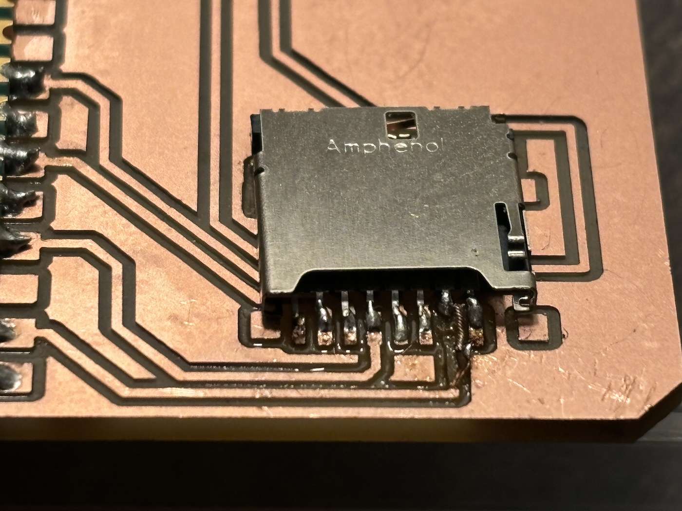
First attempt at trying to "bridge" the missing copper surface with a piece of wire. This did not work.
Picure of the first milling challenge I had - the mill did not reach the correct depth.