## Microcontroller
For my microcontroller I picked [Rasberry Pi Pico W](https://www.raspberrypi.com/documentation/microcontrollers/raspberry-pi-pico.html) as it contains the RP2040 microcontroller and has wireless capabilities.
Here's a summary of what I learned:
- Basics of microcontrollers.
- Different programming environments.
- How to program various chips and understanding their limitations.
- Exploring the vast world of sensors and actuators.
### Individual Assignment
Reading the datasheet: I tried to peruse the RP2040 datasheet with the help of gpt 4, but without much experience in embedding programming, this was initially pretty dense. However, after Quentin's office hours, I was able to get a understanding of how to read the schematics of the chip. Here are some of my notes from the datasheet and OH:
- [Schematic](https://wiki.seeedstudio.com/XIAO-RP2040/#schematic-online-viewer) of the Xiao-RP2040
- Two ARM Cortex-M0+ processors which run up to 133Hz.
- The RP2040 has a on-chip temperature sensor. I read the temperature readings as an input as an exercise.
- There are about 30 multifunction GPIO but only 14 of them that we can connect to on Xiao. A lot more pins on Pico W.
- LED pins are 16, 17, and 25 (blue). The Pico W only has a green led at GPIO 0.
- **Memory**: 264 KB SRAM
- Timers: watchdog timer and clock timer.
- ADCs: 3.3V, 2Msps ADC with up to 5 channels.
### Step 1: Get LED blinking and reading character inputs from the keyboard
The first setup included getting the LED on PicoW to blink using both Arduino IDE and Micropython. In the OH, we also went over how to read character inputs using the Arduino IDE.
### Step 2: Reading from temperature sensor and potentiometer as input.
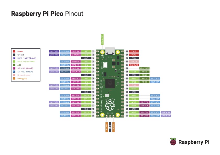
Referring to the pinout diagram below, I was able to get readings from potentiometer by connecting it to the ADC pin GP_26 as the potentiometer gives an analog output.


And, just for fun, I tried to read the on-chip temperature sensor on the RP2040 on the pico W as an input button. This was not very successful as the temperature readings were not very responsive, i.e, the readings did not vary immediately upon touching and releasing the chip which is to be expected.
### Step 3: Output: controlling a stepper motor wirelessly with two PicoW.
Thinking to my final project, I need a stepper motor or servos motor to control the sail. And for this assignment, I wanted to communicate with the microcontroller wirelessly with a potentiometer.
I didn't have access to a big enough breadboard to connect the Pico W to motor driver and the stepper motor, however, was able to get the pico W communicate with each other to blink an LED. In the coming weeks, I will be able to finish this project with my own pcb.