From Locked Out to Keyless Entry
For my final project, I wanted to build a smart electric lock for my front door, and along the way I learned to debug almost anything. I started out by brainstorming various ideas. I thought about building an electric bike, an automated pill despenser, or a LED driven art piece that mapped the night sky.
I also want to take this time to link to my personal 'textbook' that I've been making and updating throughout this course. I am hoping to use it as a continous reference to document various tips and tricks I've learned for Manufactoring and Electronics design.
I decided on the deadbolt lock. For this project I wanted to make a keypad with a LED user interface, to actuate a solenoid bolt, as well as interface with a web application as to engage my lock remotely.
I am familiar with existing commercial locks from companies like Yale, and Simply Safe. I gathered inspiration from them. I decided to 3D print an enclosure for the lock with a protective stainless shell on the outter element.
The design process began with an idea and sketch, evolving into hardware and schematic circuit design using CAD. 3D printing with PLA and utilizing the Bamboo 3D Printer, along with repurposing scrap stainless, formed the physical components.
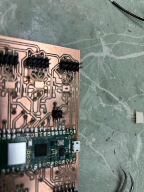
The first step is top mill the PCB for both the keypad and the microcontroller driver. In this circuit, I built out an external power regulator using a LDO voltage regulator, two bypass capacitors and a protective diode. Additionally, there is a power N-Channel MOSFET to control acutation of the solinoid valve. I protected the gate of MOSFET using two resistors, one ot ground and the other to the GPIO pin. Additionally, I added a flyback diode accross the terminals of the solenoid. The last bits of the PCB design incoorperate breakout pins for various GPIO as well for I2C. These next four pictures show the PCB in various stages of development.
The electronic key deadbolt, powered by a Raspberry Pi Pico and two 9V batteries in series, provides a secure and convenient keyless entry system for my back door. It utilizes a large N-Channel MOSFET, a 24V-rated solenoid valve, a 1.25mm stainless plate, PLA, and various passive components to create a robust locking mechanism.
Most of my materials came from the EDS Shop, however I also used the Bamboo 3D Printer from my office. Additionally, I found scrape stainless from the hobby shop recycling bin. The solenoid valve was about $10 on amazon, and a Raspberry Pi Pico is about $6. I used about $4 worth of PLA (calculated by Bamboo Studio).


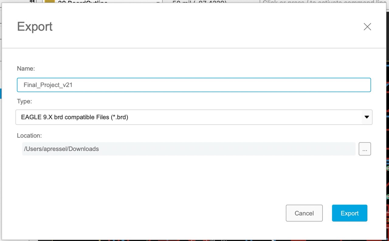
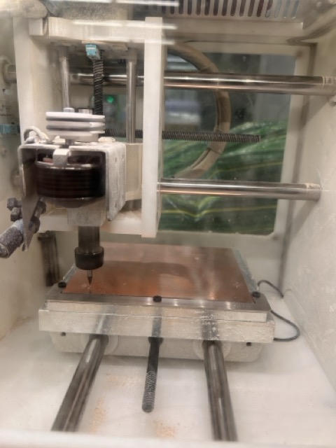
To solder the board, I went through and carefully organized the components on my notepad and taped them down with blue painters tape. I learned to use the hot air gun coupled with solder paste for this project. These next series of pictures walk through the various options to mill the board on the batum PCB Machine. I exported the ECAD as a BRD file and send it to the mill. I used the settings documented in the screen caps below.


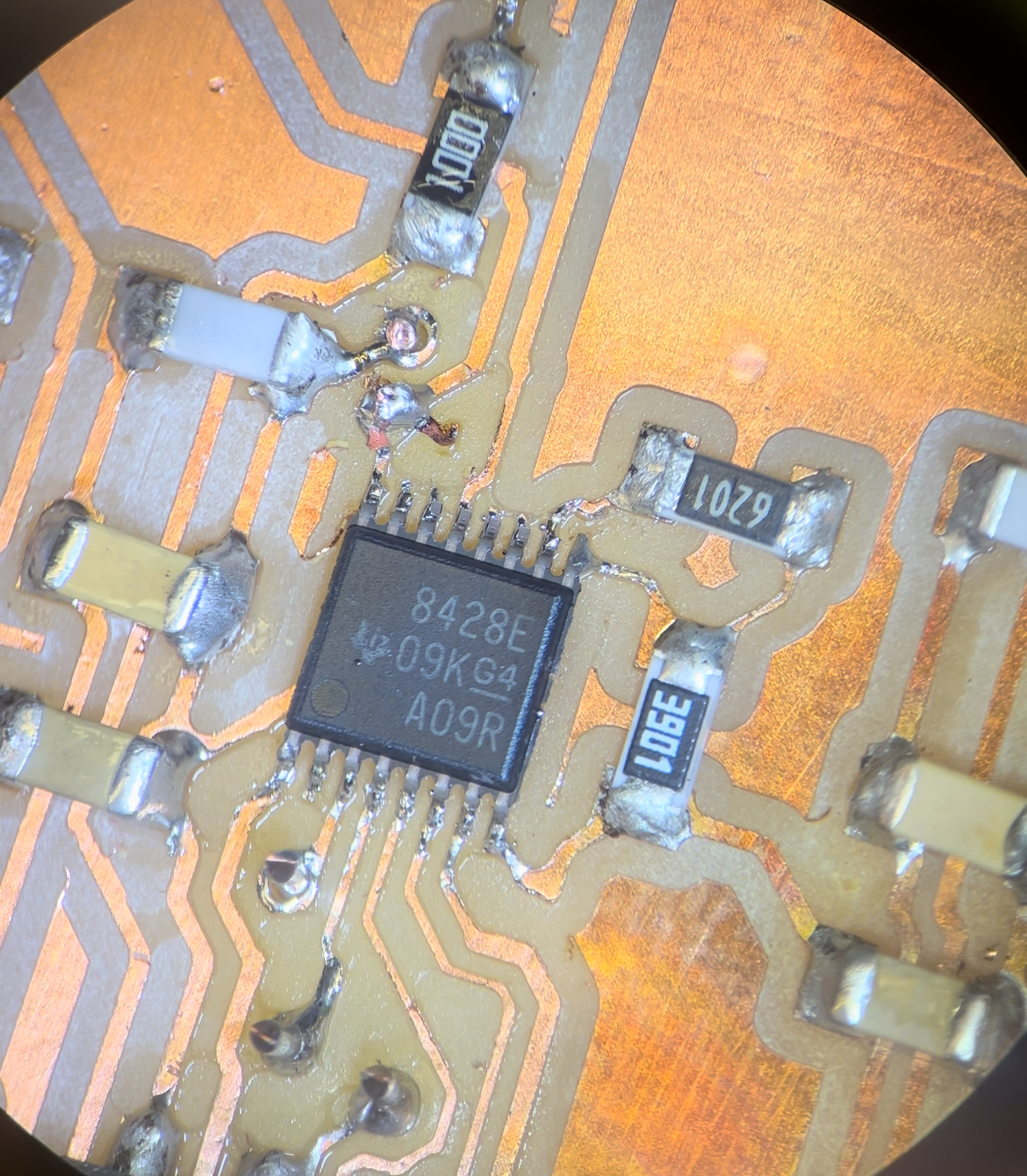
This next picture shows the super tiny pins from one of the chips I used. Specifically, this picture was taken through the microscope, I used solder paster, the hot air gun and solder wick to get these joints.
This pictures show the steps of soldering components on to my board, the last picture is when the voltage regulator shorted and I had to replace it.

The next step in this design was to print the housing for the lock. I did this in fusion360, where I imported a schematic of the PCB from Eagle. This was to ensure that the locating holes matched up with the pins from the PLA. I used a pair of calipers to precisely measure the size and shape of the various components and buttons.
These pictures show the various CAD models I made to check final fit for the lockbox. I used the bamboo printer in my office, a lot of the prints failed - I'll have to review the bamboo settings in the future.

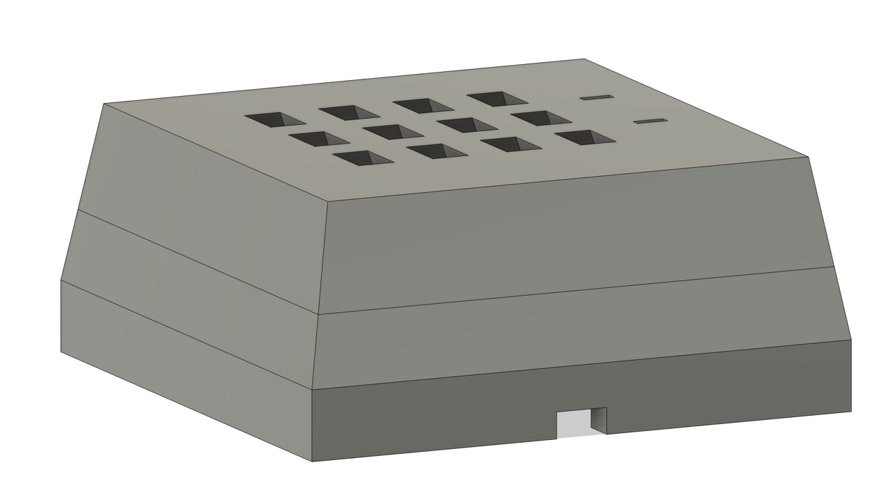

After printing all the parts I had to build the external enclosure for the keypad. The inside of it was made with PLA, but I wanted something more rhobust for the outside. I cut out stainless steel plate on the bandsaw, and used a bridgeport mill to take out the inside part. I then TIG welded it together. I used roughly the same set up from machine week but reduced my amperage from 75 to 65 to accomodate for the thinner material.


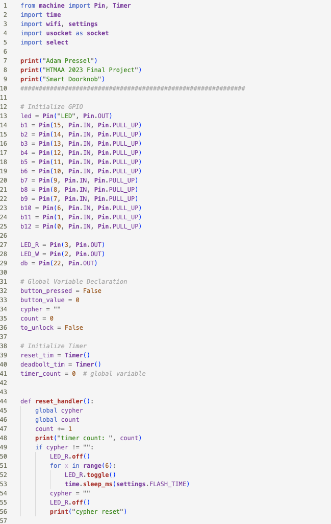
With the assembly finished, I started working on the code. I used VSCode with the micropython extension installed. I made three scripts to run: settings, wifi and main. In the main script, I first initialized GPIO, then I declared functions. I next set up the wifi, and added a websockets interface. I then moved into the main while loop, where I polled all the buttons for input. If a button was pressed, I added that key to the input code and checked it against the passcode.

and the web interface, to unlock/lock the deadbolt from my phone or computer.