HTMAA Week 5
Assignment Description:
Use an EDA tool to design a development board to interact and communicate with an embedded microcontroller
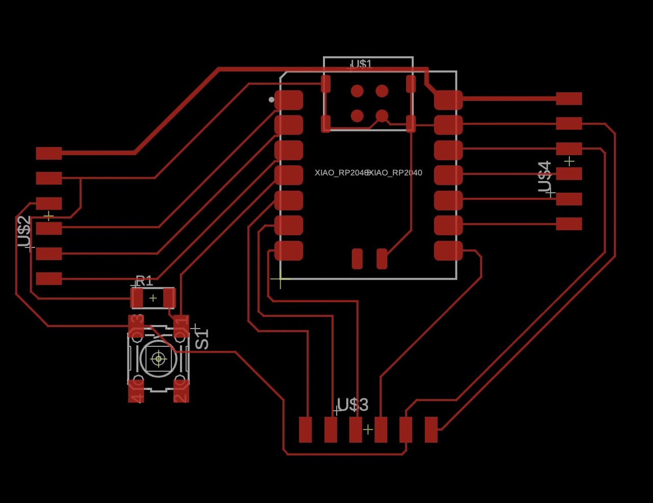
Final Board Design
This week I took my first foray into electronics design. I took an introductory electrical engineering course in undergrad, but it was shortened and fully virtual due to COVID, so I have distant memories of analyzing circuits, but no experience designing them for any real use. Therefore, this week was mostly spent conducting research into the tools and design process. The recitation and video tutorial from 2021 were key in providing the footing for using Fusion 360 (Eagle).
Fusion 360 File
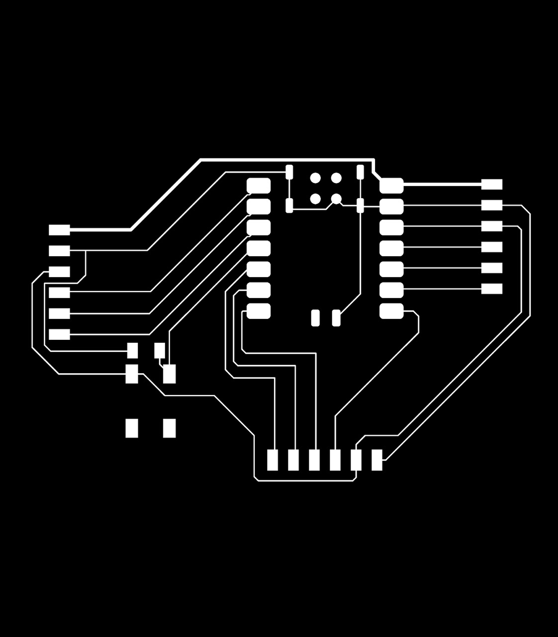
Trace PNG
Intro to the Seeed RP2040 Xiao
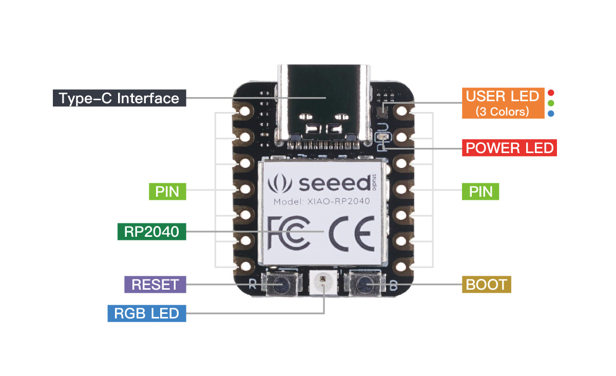
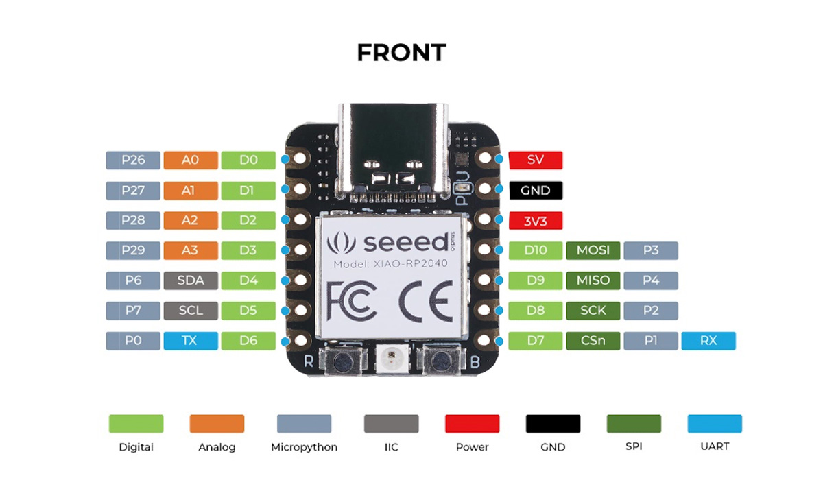
During microcontroller week I used a Raspberry Pi Pico W (which is powered by an RP2040) attached to an e-ink display. In order to get experience with the Xiao package as well, I designed a board to breakout the pins for the Seeed RP2040 Xiao for future use, potentially in my final project to interact with sensors for my hydroponic garden.
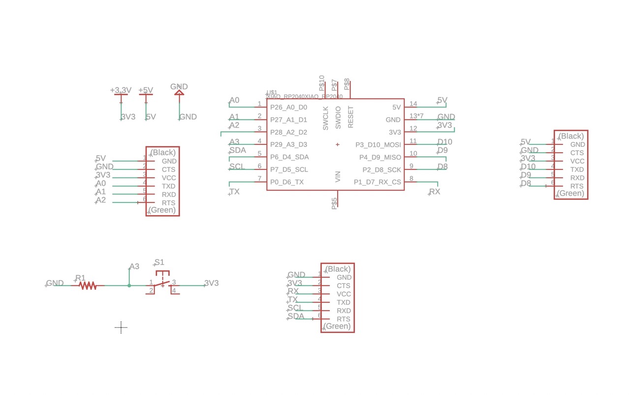
After the recitation and watching the EDA tutorial, I had a grasp of how to use the tool, but not of what I actually needed to do. So, I next read Seeed's getting started guide which laid out the pins present on the board. I was confused by the fact that the documentation mentioned many more pin functions than physical pins on the board. To clear up that confusion, as well as many other questions (such as the #V# naming convention) throughout the journey, I asked ChatGPT. The conversation can be viewed here. Essentially, the 11 non-power pins have multiple functions that can be controlled via software.
Design
The example Neil showed in class was a massive help in demonstrating the thought process and the core components of the board. I decided to add a button to the board for testing with programs in the future. I connected the button to one of the analog pins as it seemed like the only option that would not remove the potential to communicate with one of the supported protocols. Moreover, I opted to not include an onboard LED as the Xiao package includes 4 already and to conserve pins.


As described in the tutorials, I used these DRC rules (16 mils, 6 mils).
EDIT: During production in week 6, I discovered that 6 mils is too narrow for the traces to make a quick and consistent milling on the OtherMill. At production time I changed the trace width for all traces to 16 mils.
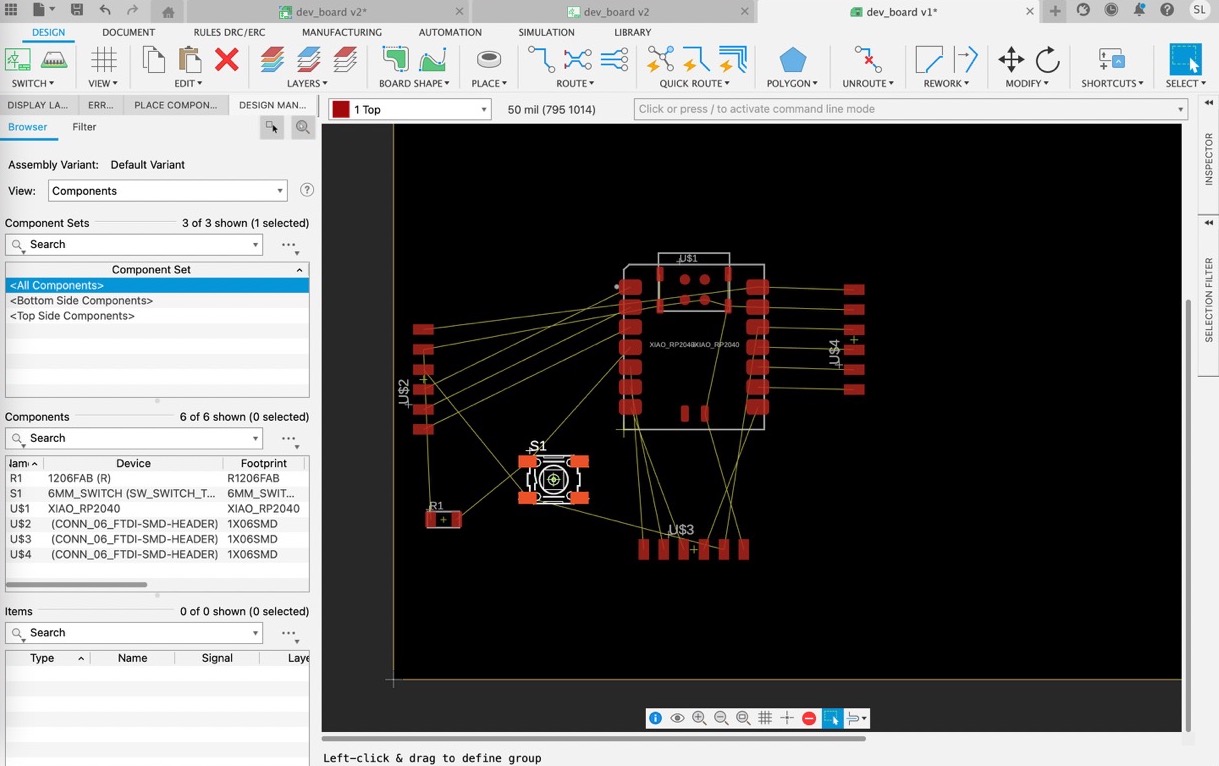
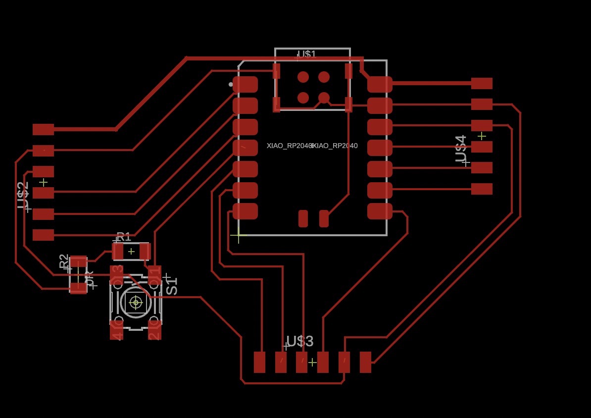
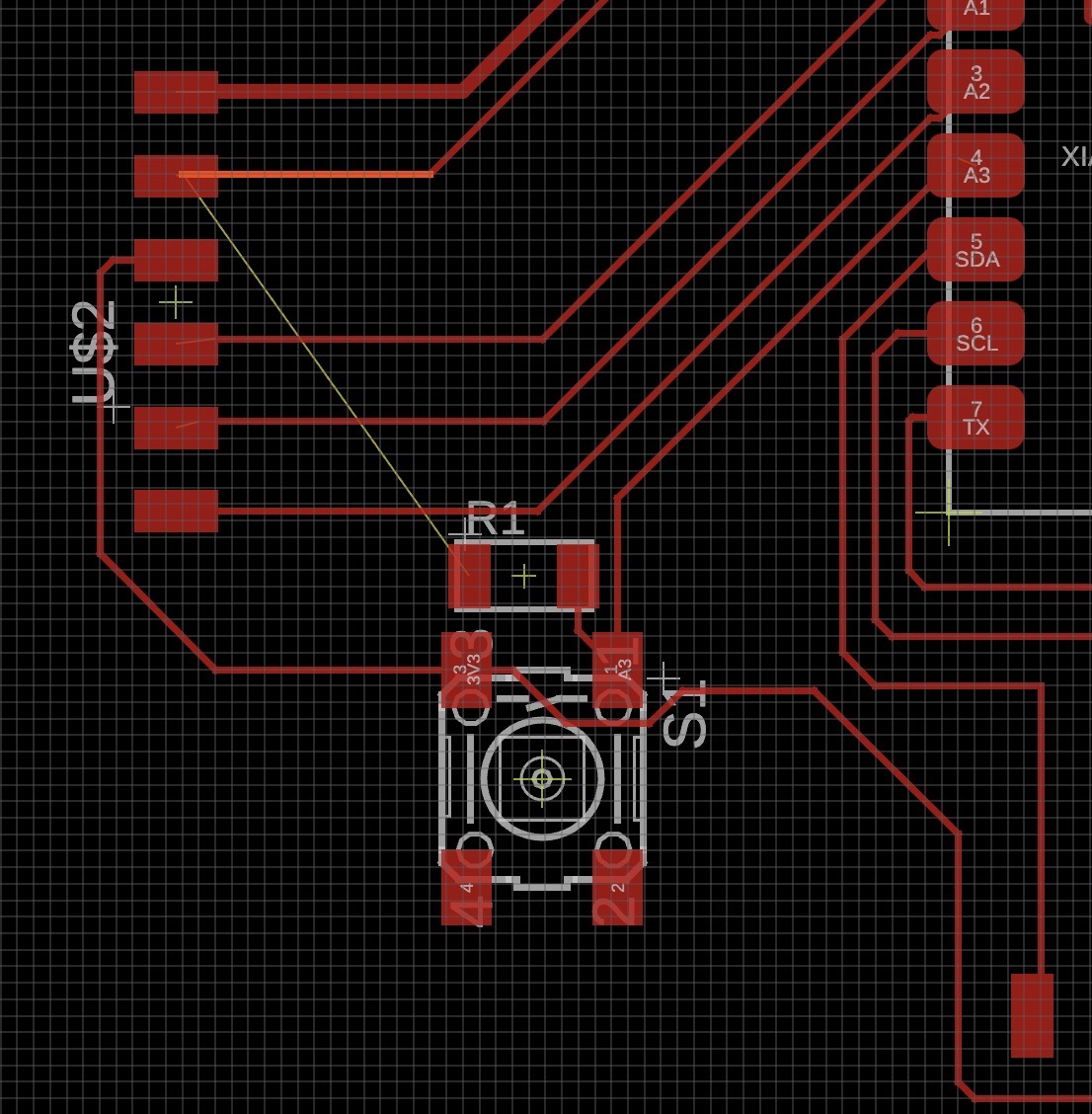
After finishing the schematic, I began to design the board. I drew wider (0.4mm) traces for the 5V power lanes. Routing was not too difficult and was pretty fun, but I did run into an issue with an air wire existing across a resistor. I was attempting to use the 0 Ohm resistor bridge trick (bottom left), but the software was not having it. I assumed that it was user error, so I scrapped that strategy and re-routed a bit more.
Although by the end it didn't feel like I had created anything particularly profound, I had a lot of fun this week. The world of microntrollers, PCBs, etc. has always been intimidating to me, so to really feel like I am sinking my teeth into it is awesome. I look forward to milling this board, hooking up some sensors, and improving upon the design for my final project!