Week 9 - Output Devices
-
Servos, servos, and more servos
One of the challenging elements of my final project (prosthetics) is actuation. Being able to control 5 fingers individually is a design problem (in how to design the mechanism) but also an electronics problem (how to power 5-10 servo motors from one pcb).
Video on the left shows 5 servos working at the same time, at that time still from a breadboard (milled the board later). -
Isn't it just 10x3 connectors?
Mmm, yes and no. That's what I thought at first - it's going to be easy. Let me describe the challenges as they appeared, one by one.
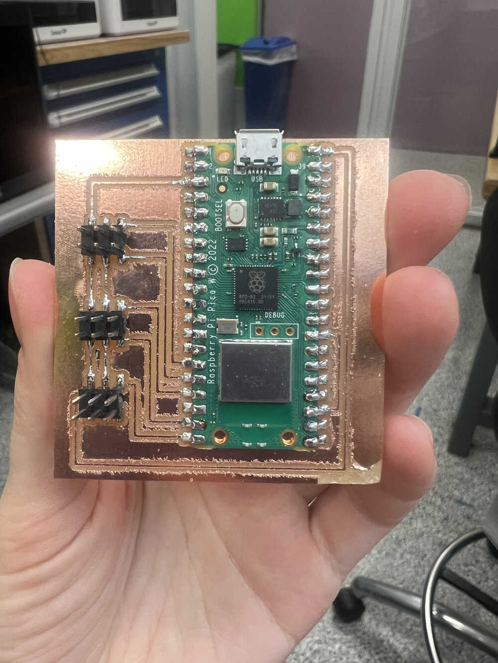
Initially I picked an Arduino Pico RP2040, because it has a lot of pins and has the potential to accomodate 10 different servos. I went ahead to mill a board (Initial brd file with the board) and added the connectors. Design is super simple (I bet I wouldn't have said it during the electronics design week, when I struggled to understand what's going on; that's how you know it's not your first pcb design).
Milling and soldering process steps are on the right. As you can see, the first potential problem is the fuzzy traces - seems like that drillbit needed a replacement, but I was told that it's fine and I can go ahead with this board. Soldering wasn't too complicated either, except it was my first time soldering all the pins of Arduino pico, which is way more than Xiaos have.
-
Problem n1 - range of servo motion
So I went ahead to test the servos. And the first issue I hit was that they wouldn't move 180 degrees (declared range of motion of both small and large available servos was 270 degrees, definitely above 180). You can see on the video on the left how it was trying to move what it thought was a 180 degrees range, but was only getting to ~90. The code this test was using was an example library sweep in Arduino IDE (can be found here).
According to Anthony, there is usually a gap between declared range and actual manufactured range, so the trick is to just override the range values. I say "just", but in fact it took a lot of debugging to figure out how to override the values and not to be overriden by the library values.
Answer was actually found in the library source code - in the setup() loop, you can specify the range that is bigger than the declared 1000-2000 range:
myservo.attach(26,700,2500); // attaches the servo on pin 26 to the servo object, sweep in range 700-2500
Values 700 and 2500 are experimentally acquired - check them with your servo if you try to reimplement the project. -
Problem n2 - Too Many Servos(?)
"I don't know how you managed to, but you nuked Arduino Pico with servos" - (maybe) Anthony.
Next challenge of the story was to power all the servos from one board. I was incrementing actuation of several servos at the same time, and at some point (number of servos = 4) the board stopped responding. Video on the right represents me trying to record the video when the motor stopped (and I assume the board fried).
After that I wasn't able to even connect to the board, it wasn't getting detected, and refused to upload the code/run otherwise. I believe that it was because the Arduino got overloaded by actuating so many motors at the same time.
It was sad, but definitely a learning experience. Alternative suggestion for this problem was to power the servos from the 5V outlet, and power Arduino from the laptop, which actually solved the problem at the end of the day, and propagated into the final project.
If it didn't work, however, my plan was to mill 5 boards for 5 fingers, so that I can actuate them without overloading the board. -

Attempt n2
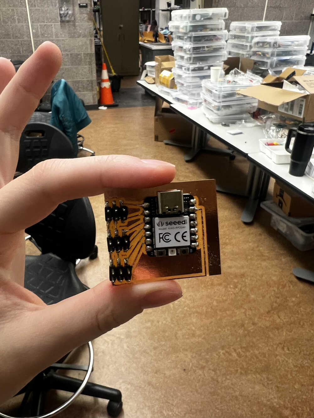
After this experience I redesigned the board with following idea in mind: I switched to Xiao RP2040, I still had 6*3 connectors, but now 5*3 of them are responsible for the motors, and the 6th one is for the power. The power source just takes two inputs, ground and 5V, and gets connected to the circuit in that way. It is hard to judge from the Fusion file, since all the elements are connectors, but here is a brd file.
These traces were nice and neat (finally!) and the board looked promising. Let's put it to work! -
Integration
After having dealed with all the power issues, coding wasn't that hard. On the right you can find some videos from final project where this board and system was integrated. You can see the power supply and all the motors connected.
The code for motors was pretty easy once I have resolved the motion range issue. You can find a version of it here. It just sweeps all 5 motors in the range of approximately 180 degrees, which is probably a boring application, but it is an application.
A more involved application I did with the motors was final week. You can find the code for it here. More details about this implementation are on final project tracking page, which explains more detailedly the context of this code and how it was designed, but as a result - it makes all the fingers of the final project move in a deterministic manner.
(Note: the robotic hand itself was build on a later week - this is just a video of how the system got integrated.) -

Conclusions
This week has shown me complications of systems from non-software side - pcbs can be shorted, overloaded, or just not connect. Thinking of external power was important learning lesson for this week.
As always, thanks to Anthony, ChatGPT, and Github Copilot for helping me!
I don't really see a good further project for this week, except from maybe stress testing the board (how many servos it can hold). There weren't more than 5 big servos at a time of the project, and I'm not sure if the lab would be happy about me stress blowing up the mictocontrollers, so I'd leave it as a highly hypothetical and not-to-be-implemented project.