Final Project - Prosthetic Manipulator
-
Motivation & Overview
Important Note: top video is a video where is has a very quick recap on how the project was built. Bottom video is a demo of a working system controlled from GUI. Below is a summary slide of the project.
Quality isn't great because of file size limit. Please find Google Drive options linked here: Summary Slide, Demo, and Final Presentation, and at the right. I didn't get to give Final Presentation because I got COVID. There was a very extensive checklist posted on the website regarding final project presentation, check here for details.
As I was brainstorming for the final project, I was reflecting on what is something that I can do, which is challenging, but also useful and makes this world a bit better.
A little asterics. I am originally from Ukraine, and my world is going through a lot these days, so I was thinking of what are the biggest impacts I can have in supporting my country these days. Well, this class claims I can do anything here right? Time to dream big.
The two main candidates I had were drone manipulators and prosthetics. First can definitely have a lot of impact on the field, second have a lot of direct impact on people's lives - especially soldiers, who already went through hell, and might need to keep fighting this life if they have a disability now.
So my decision landed on prosthetics (I still plan to work on a drone project, but beyond the scope of this class). Prosthetics is a very interesting and challenging product, and optimistically, I can try to optimise price, functionality, and aesthetics of the product. But realistically, I have to start with something that works, and attempt some unusual design desicions as a part of an experiment.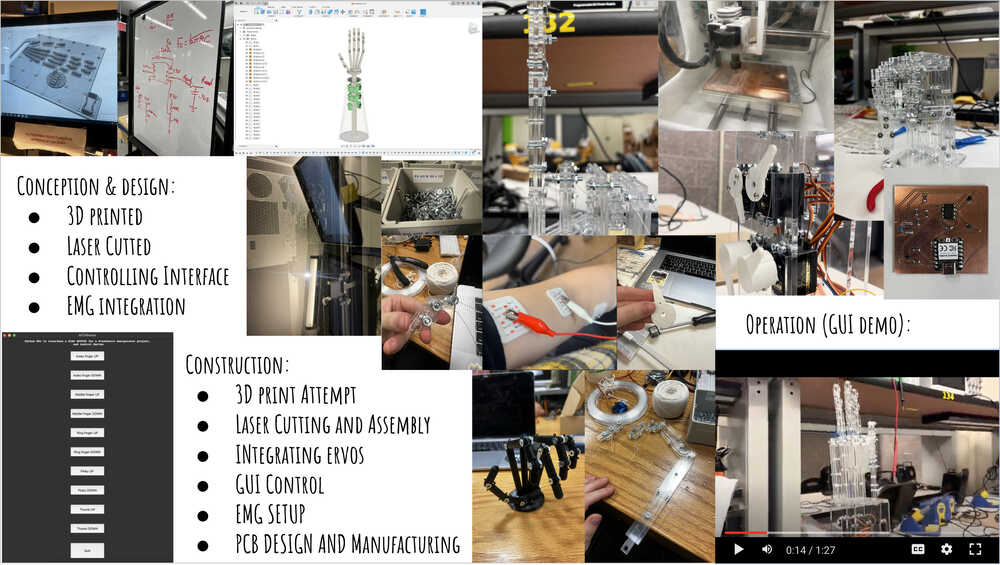
-

Research of the Field
I am not an expert in prosthetics, frankly I had very minimal knowledge to begin with. One incredible resource in understanding prosthetics came from a conversation with a friend of mine, who wears prosthetics himself and worked with Biomechatronics group when he was an undergrad.
Important findings from the conversation:
1. There are two main types of prosthetics: passive and active. Passive prosthetics are the ones that are not controlled by the user, and are usually used for cosmetic purposes. Active prosthetics are the ones that are controlled by the user, and are used for functional purposes.
2. Leg and arm prosthetics are very different. While both share similar challenges of perfect seal, comfort, weight, leg prosthetics are a lot more focused on having the joint being stiff, and some versions just control the stiffness, hand prosthetics are more about manipulation and control.
3. Force sensors are challenging, hence are the problems of squishing a ping pong ball vs a cup - force sensors really depend on what the manipulator hand is holding and are a challenge.
4. It's pretty common for people to choose not to wear arm prosthetics or just go with a simple hook - since a lot of existing solutions are not so efficient, and there is not a "one fit all solution".
5. 3D printed hands are a thing, they are way cheaper and customizable. One of the favorite types he mentioned is stuff like octopus hands - a good way to think of prosthetics as a superpower.
6. In terms of actuation, there are two main types - one has a limited number of main manipulation tasks and user picks them by pressing a button with another hand. Another type is muscle sensors, and actuation by contracting them. -
Formalizing Idea and Modelling (V1)
After learning more about the current state of the field, I had to formalize my project. The key design decisions are:
1. Carbon fiber is a great material for prosthetics, it's light, strong, and it is a most commonly used material, especially for the leg prosthetics. I plan to complete the forearm of a prosthetics using composite process, however, I will do it after the final project presentation, since it rather a good improvement than an MVP.
2. I will use a 3D printed hand, since it's a lot cheaper, and I can customize it to my needs. I will use TPU especially for the fingers, so that it is easier to grab objects if needed.
3. I will explore various actuation methods, and will start with a simple one - a servo motor. Another attempt that came up in a wildcard week is usage of artificial muscles - a great and unique application of artificial muscle, however, a little slow.
4. I will control the hand either by a button/computer interface, or try to incorporate muscle sensor if I have time.
5. Finally, I will aim the hand to be able to perform some basic task - I initially thought of it being able to reproduce an ASL (which is more tricky than you think if the fingers don't move sideways), but will probably go with something as trivial as just closing a fist.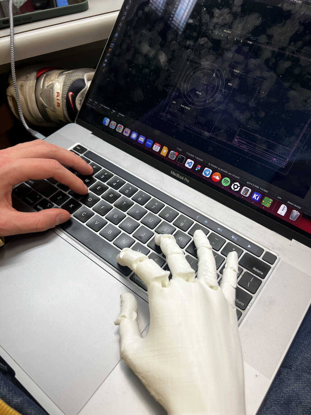
-

Structure (V1)
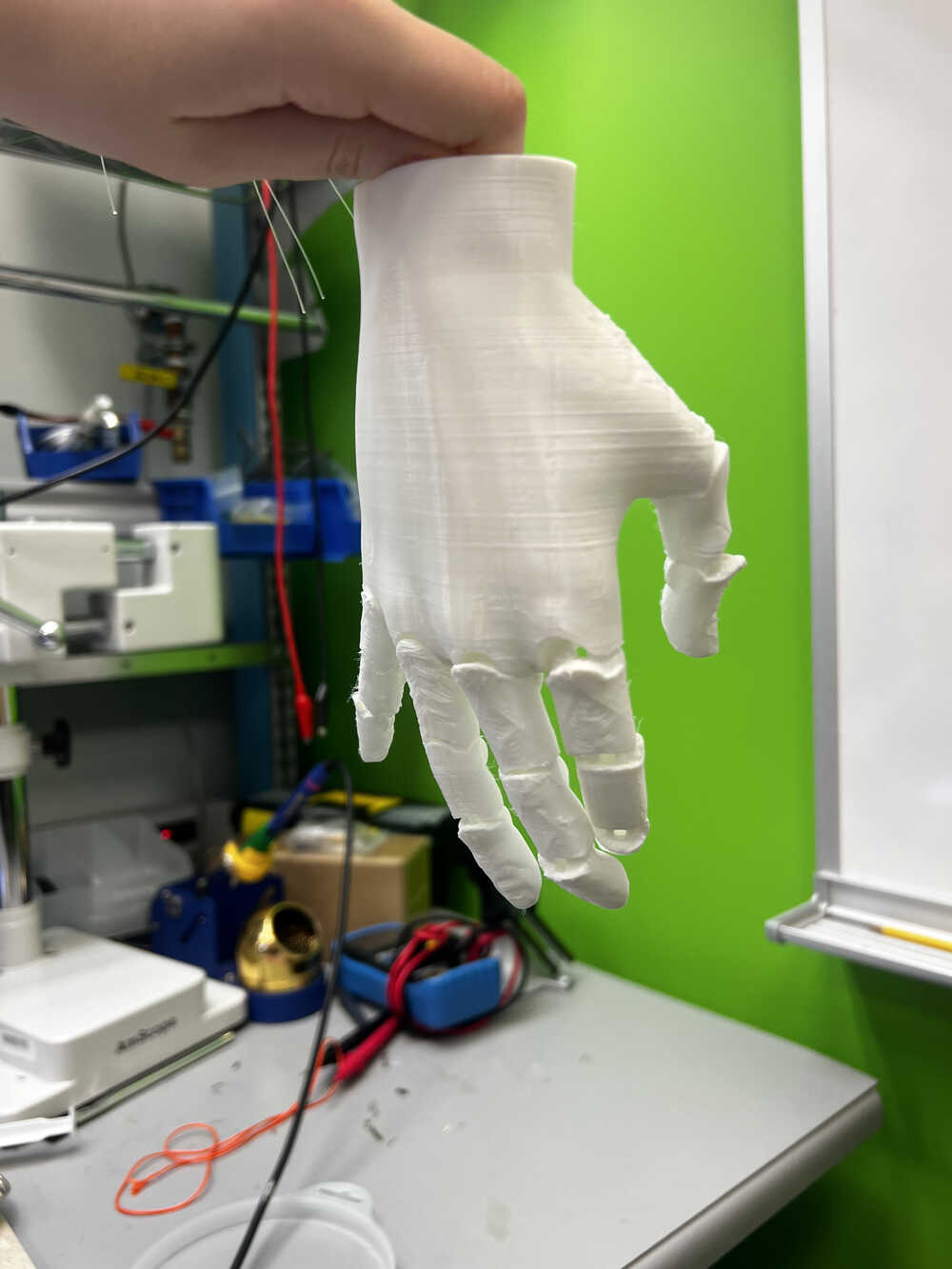
My first iteration was trying to use already existing 3D models found online and print them from TPU, and improve on the mechanism as needed. (I only then realized that CADing was part of the final project goals, however, it didn't work as well as I wanted anyways). The connections were done using a fishing line and they wouldn't nicely twist. Additionally, the quality of the print iteration was a little hairy, which I fixed with scissors.
-
Side quest - Artificial Muscles (V1)
When I saw on Wildcard Week Articial Muscles, I was amazed, I thought that it is that connection of bionics and robotic hand. I have a very detailed story about how it went at week 13 page, but let me give a brief summary here.
Artificial Muscles is a way to make things move seamlessly by using a thread-like material that shrinks when heated and extends when cooled. The concept itself is amazing, and Jack was great at presenting and explaining how to use it. The main trick is to braid those threads with conductive threads that heat up when the current goes through, which allows for the shrinkable material to receive the heat changes (top video illustrates the mechanism pretty well).
The video on the bottom shows a 10x speed video of trying to flex the finger by applying current to the system. Here comes the first bottleneck of the system - it is slow and not very strong. -
Side quest - Artificial Muscles (V1) contintued
I had a few more iterations of trying to imitate the muscle, with relative success. It was a very fun time watching the muscles twitch just a little on a 10x speed, or being sad that something didn't work just to rewatch the video and know that something indeed worked. It also felt like a very artsy deviation from all the electronics of this class, with the system not working perfectly or fluently. For example, one of the learnings of this system was that the stretcheable threads need to be preheated before braiding, because they are slightly extra stretched during manufacturing, and they wouldn't recover to that length, but rather to some intermediate length.
As fun and cool as it looks, I had to decide against this idea. The main reasoning being: the muscles move too slow. It also didn't give much power, which could get fixed by getting more material, but from actual prosthetics perspective, it isn't practical to receive a signal from muscle in the upper part of the hand and wait for a minute for the fist to contract. Cool research and experimental project, but not for human-usable prosthetics. -
Structure (V2)
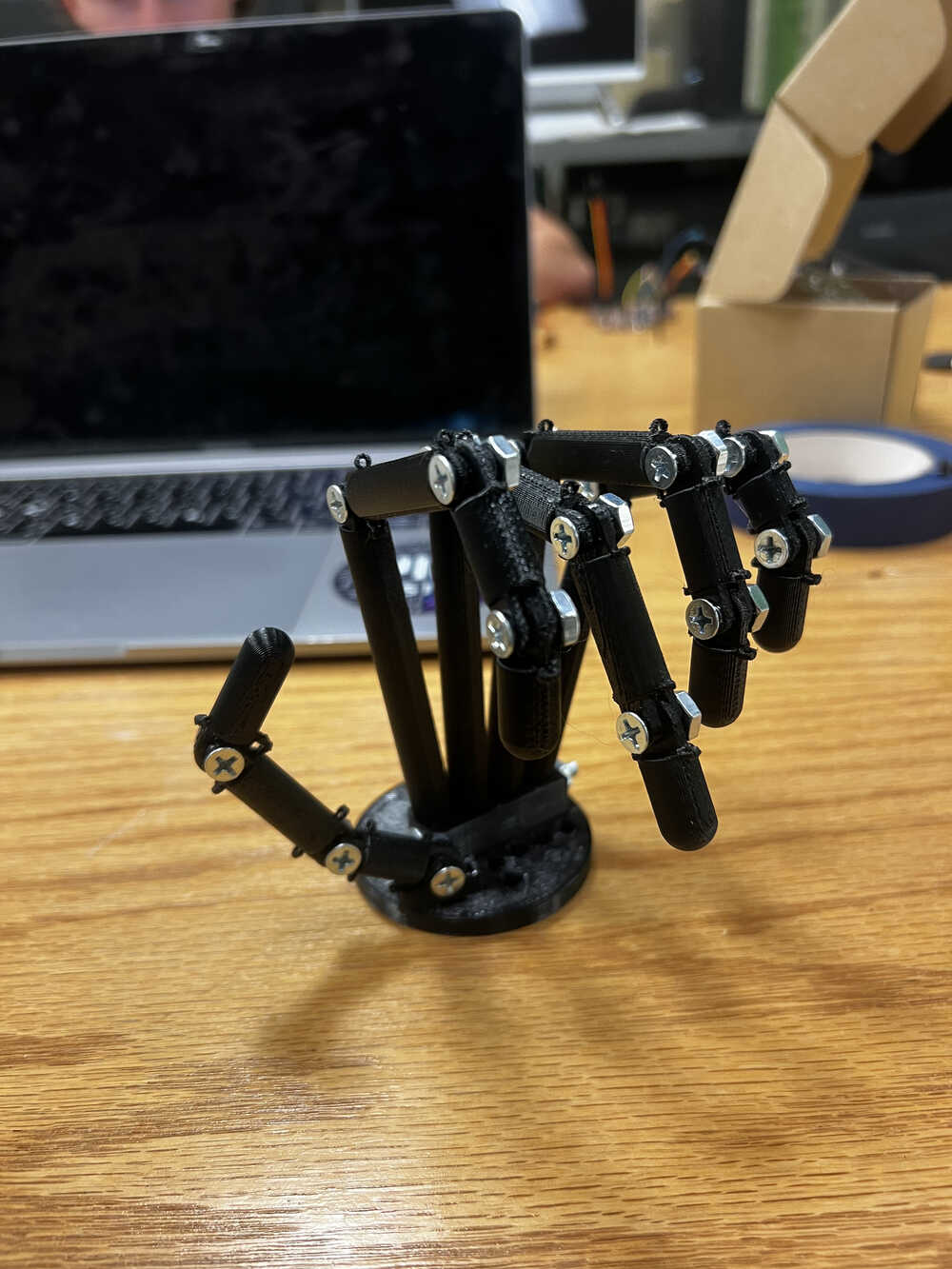
In my second iteration I decided to design the hand myself and print it using normal PLA. Designing a hand itself was a big challenge.
Designing a hand itself was a big challenge. It is generally difficult to design bionic structures.
This paper was an incredible inspiration for my design. Although they didn't publish their 3D printing files, the paper gives a lot of detail of the design and how to set up this system if I am trying to go biomimetic pathway.
It might not look like a perfect biomimetic hand, but this was my best attempt at CADing something that moves biomimetically. Slightly more expanded description of working on this CAD model is in Week 0. And the CAD file of that version can be found here.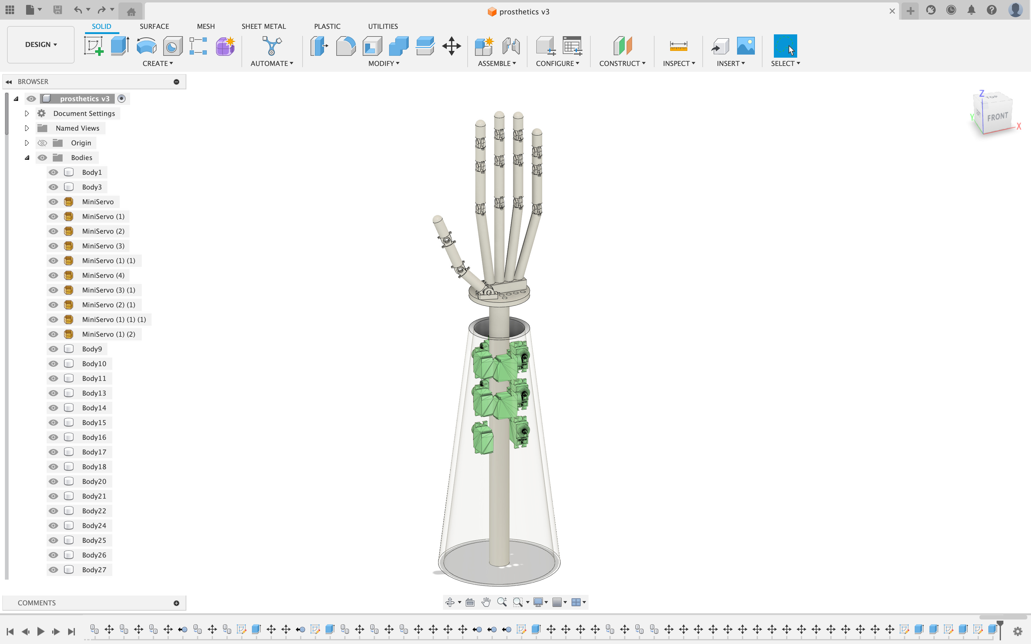
-

Making (V2)
Now this STL file and design looks way more promising than the previous one. It implies there being little strings immitating flexor and extendor muscles on each finger, which imitates biomimetic system.
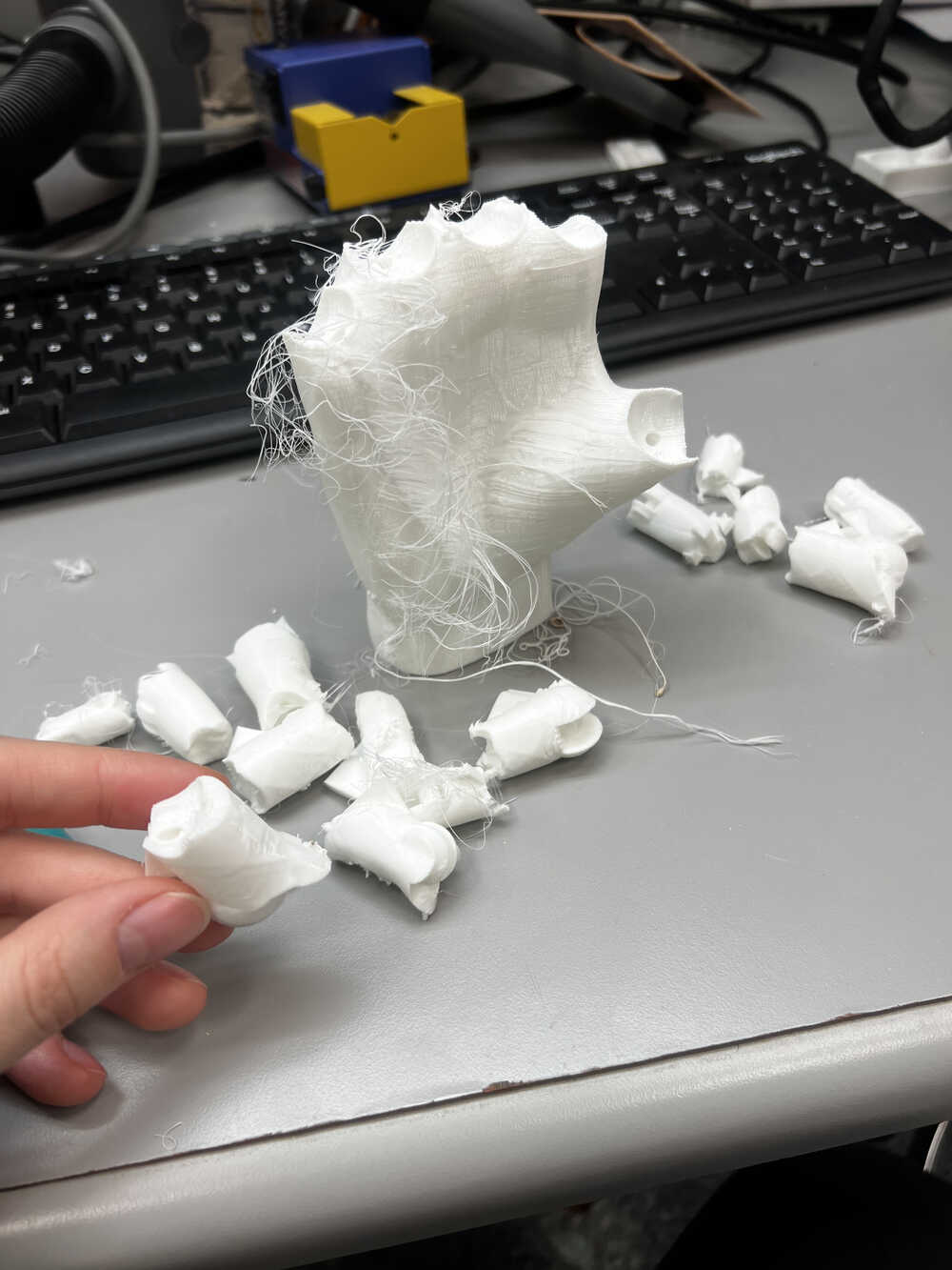
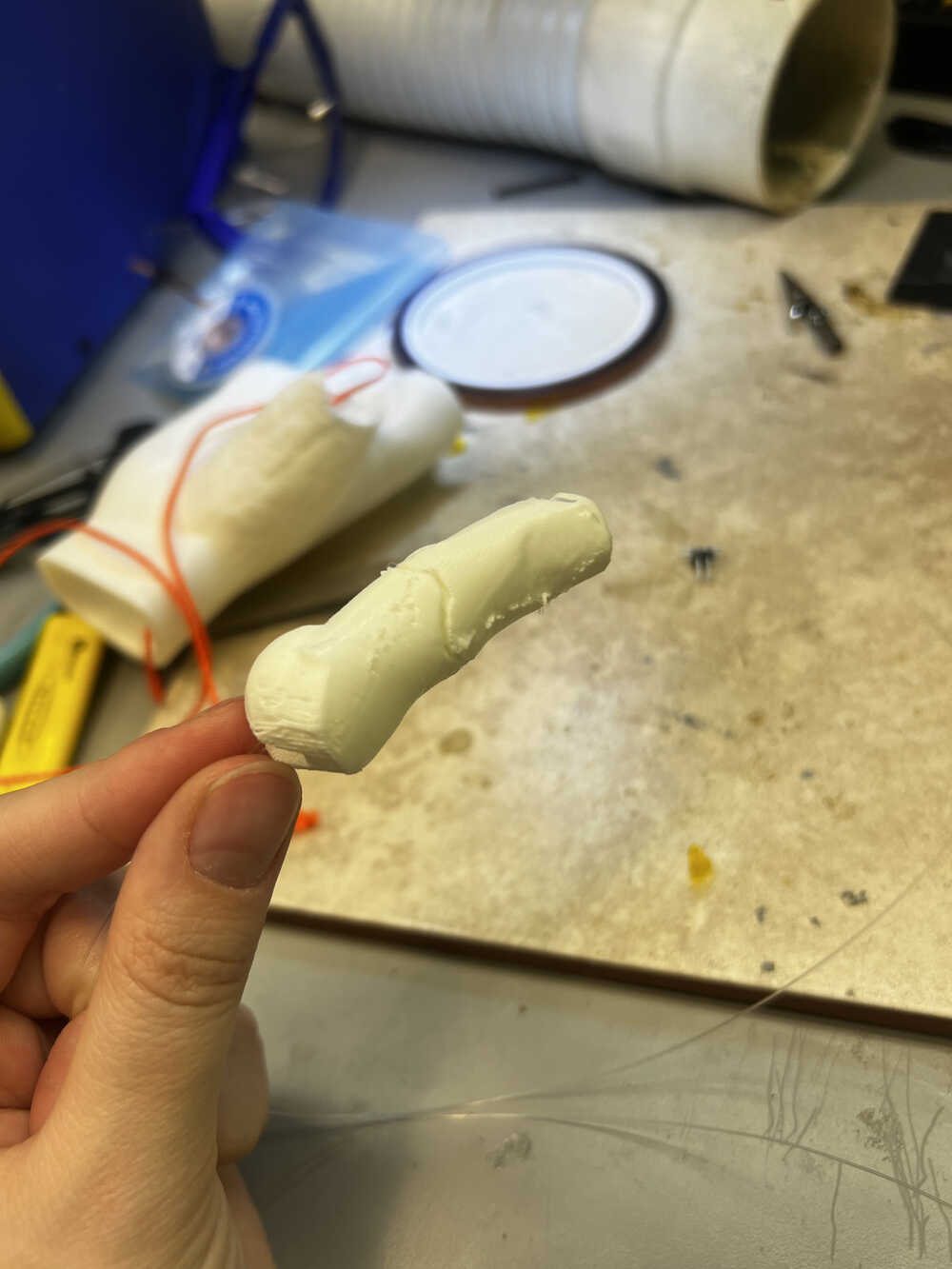
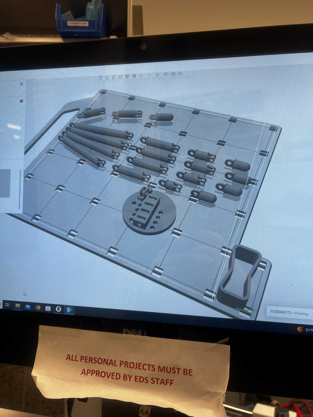
Time to make! The parts vere small and I didn't want to deal with supports, so I put the hand design in the printer with dissolvable support material. -
Assembly (V2)
The print came out pretty nice actually, and wasn't too hard to assemble. I was using 8-32 1/2" bolts and nuts for all the joints, and the whole design was made for the system not to be very tender like V1.
However, even as I started assemblying, one or two of the little rings broke (the ones which were supposed to hold the flexors and extedors). I decided that there might still be a way to deal with it and kept going.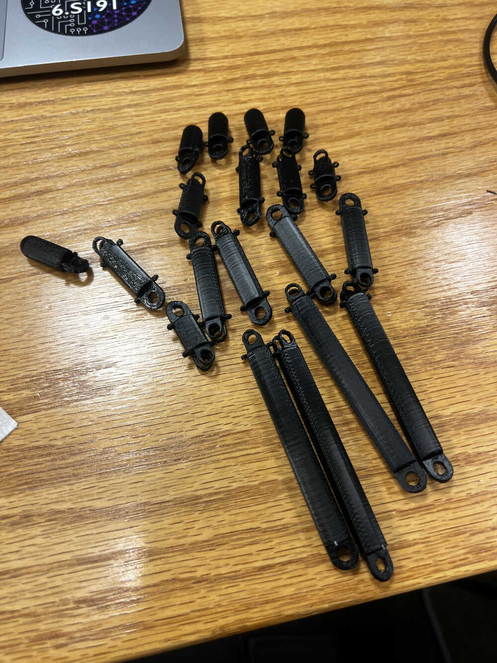
-
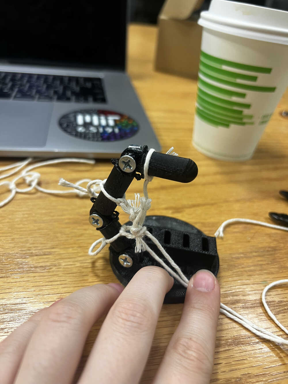

Looks cool, but how do I make it move? or Actuation (V2)
I thought design was the hardest part, but it was just the start. Here comes N hours of me trying to engineer something using my system and threads, breaking more and more rings, getting frustrated and getting questionable actuation mechanisms. I was trying to get as close as possible to the paper mentioned above, however, it was really hard to map their work on my model.
-
Back to Fusion360 (V3)
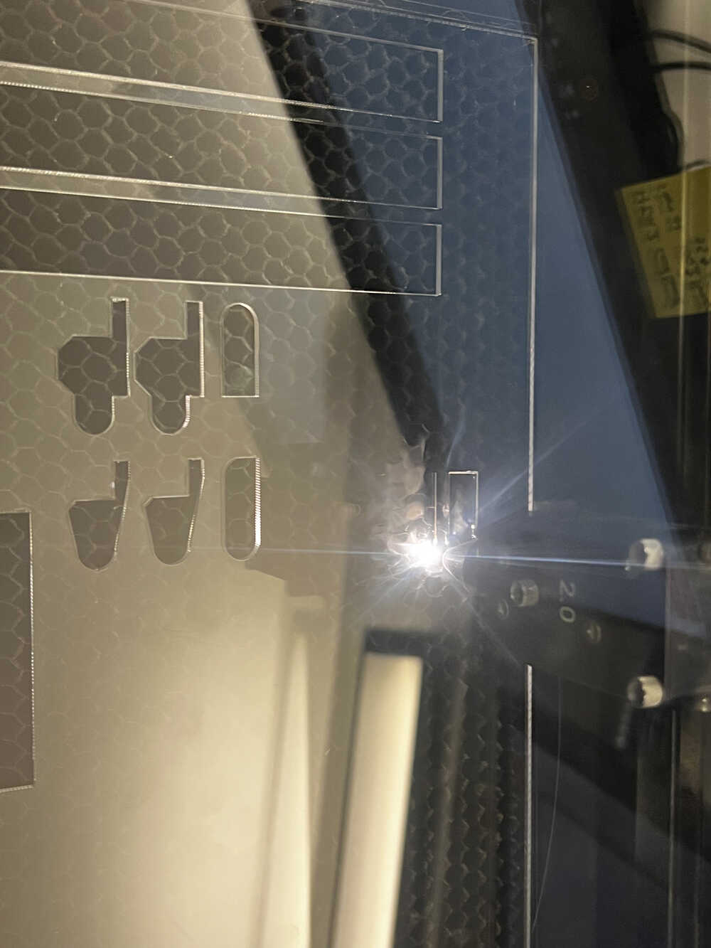
I thought I'm done with CADing of the project, but no, not at all. The system I designed above didn't give anticipated results, so I had to think of something else. I got some tips on making a channel for the strings and scale up the system, and I tried to fix my 3D model to print it again, until I realized that there is an easier and faster way to do these kinds of channels - using my favourite tool from this course, laser cutter.
Laser cutter gave me a lot of benefits in this case:
1. I could use transparent acrylic and keep bolt system - feels more stable, hard to break, aesthetic looks.
2. The channels were very easy to make, I was just bolting together three layers of acrylic which was natural to just do different shapes of layers to do channels, channels were pretty big and easy to connect strings to the bolts.
3. I could make a lot of iterations of the system, and it was very easy to make a lot of them, and I could make them very fast. I looove that laser cutter takes minutes to make something, compared to hours on 3D printing, as well as having many different parts made it easy to fix just a few.
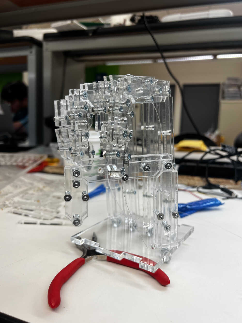
Back to Fusion, now I had to make new design, but now it is 2D. I indeed scaled the system to the size of connector bolts that there were plenty of in the lab. I made several iterations and ended up with the following design. This and this are files for the base stand - not really a functional system, but rather for stability.


-

Joints and Mobility (V3)
Laser cutting was quick, I had to redo some parts due to my infamiliarity with acrylic (I didn't know how to adjust the power to the material properly, didn't know that I shouldn't remove protective film before cutting, picked different thickness of material, and other small oopsies, which, however, were quick and easy to fix).
When lasercutting, I made places for servos to be placed, so that the string tension is nice and deterministic.
Next step was assembly, which was somewhat time consuming, but again, all parts were designed to nicely fit into each other connectors, so it was pretty smooth. There were a few issues however, like:
1. After continuous movement some bolts were unscrewing. I was adviced to double bolt or glue, so that the joints are moveable.
2. I needed to find a good balance between a tight screw (which is needed to keep 3 layers together) and a light screw (which was required for being able to move the joints).
3. I had a system designed so that the fingers cannot unflex beyond 180 degrees, however, fishing lines sometimes were getting in the gaps between layers.
4. I was sceptical about the motors being able to move a relatively heavy finger, so I considered making a stand sideways, to reduce load. Eventually, it ended up not being an issue, since the motors were able to move the fingers just fine.
5. I tried to locate a thumb imitating real life, but in fact, it felt rather in the way most of the time. In interest of time I decided to just have the order of finger extensions being reasonably chosen by deterministic algorithms or human through interface. -
Let's move them! (V3)
This part of the project with its own shenanigans is very detailedly described in the Output Devices' week page, but let me give a brief summary here. The main idea is to use servos to control the motion of the fingers. I initially thought of having 10 servos for controlling all the fingers, but eventually designed a system that only requires 5.
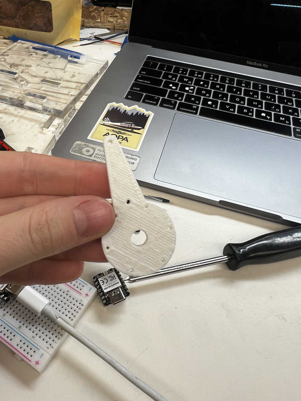
Another improvement was 3D printing the connectors from the servos to the fishing lines (CAD file), so that the range of motion of the servo translates nicely into the motion of the finger. This was part of the design decision, iterating on the existing heads that go together with the servo motors, which I was prototyping on.
One of the cool findings I had, is that there is a way to tie up the fishing lane to that head so that the top part (extendor muscle) has a different length going from 0 to 180 than the bottom one. The main idea is pretty much connecting them on different distances from the center of the rotating motion - so that when the servo rotates, the paths covered are different.
Another interesting challenge was designing and placing the 3D printed parts so that the strings don't get tangled against each other. The main idea here was to direct the strings to the opposite ways (for index and middle vs ring and pinky), and designing some of the heads taller than the others, so that the paths of servo motions wouldn't overlap.
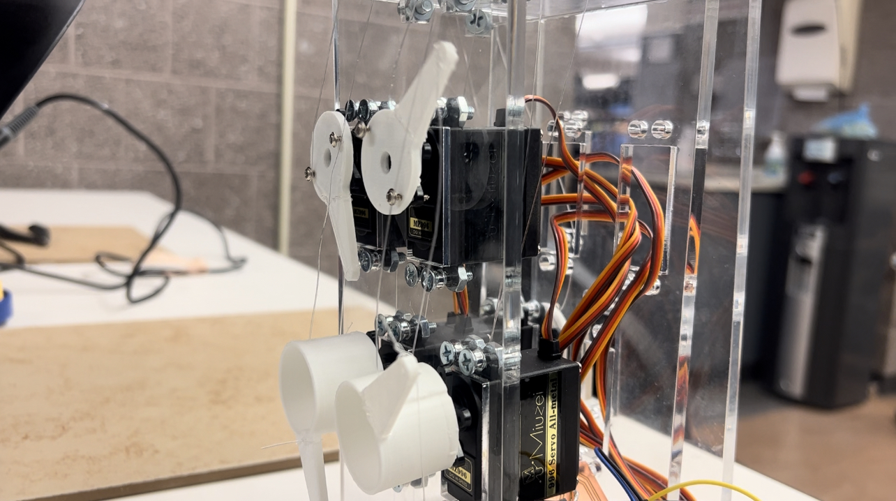
Images on the right show more deatiledly design of the heads and how do they look when put together in a system. As you see, they have different heights, and they all try to rotate externally.
Note: there are slightly more holes in the system than needed, however, I didn't quite need to fix the laser cutting parts. Those holes provide a nice routing for cables, slots for boards, although they were not exactly designed for it initially.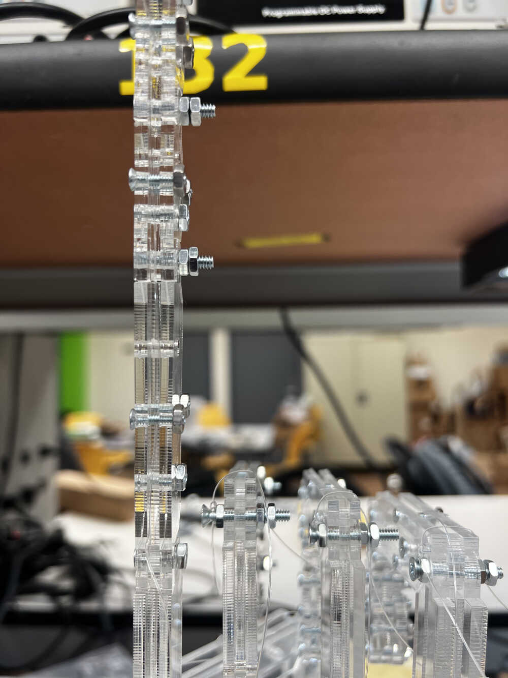
-
Let's move them! (V3) continued
Setting up servos had quite some troubleshooting on its own (detailedly described in week 9 writeup). One of the interesting bugs was that the declared 0-180 motion of the servo does not at all correspond to the actual motion, and needs to be overwritten. The top video shows me struggling with understanding why I am not getting the correct range.
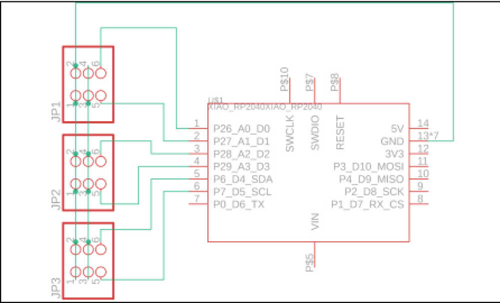
Then I hit an error of having too many servos connected to the board and trying to get powered from the board. The second video shows me troubleshooting several servos on arduino Pico RP2040. It ended up breaking the board, so I switched to the design of powering the servos externally from the 5V power outlet, and remilled the board. Here is a brd file of the updated board; I switched to Xiao PR2040, since I already realized that I don't need all the pins from the Arduino Pico. -
Integration of Servos (V3) continued
After having dealed with all the power issues, coding wasn't that hard. On the right you can find some videos from final project where this board and system was integrated. You can see the power supply and all the motors connected.
The code for motors was pretty easy once I have resolved the motion range issue. You can find a version of it here. It just sweeps all 5 motors in the range of approximately 180 degrees, which is probably a boring application, but it is an application.
A more involved application I did with the motors was unfolding and folding them multiple at a time. You can find the code for it here. As a result - it makes all the fingers of the final project move in a deterministic manner, which proves that the physical design is correct. The bottom video is missing a thumb integration, I was connecting them one at a time and making sure that they all work. Thumb itself was a special finger because it overlaps with others, so it needed a more careful consideration. -

Control (V3?) Electromyography
Once the system was physically moving, it was time to configure control of it. I had several ideas of how to design it, and I will unfold them separately.
V1 of the control was articial muscles, which I already described above. It was a very cool idea, but it was slow and not very strong, so I decided to not go with it.
V2 was in the videos above, just some deterministic code to move fingers continuously. I was given an idea to make this hand play rock-paper-scissors, which would have been a fun one, but I tried to go closer to actual usecase.
My initial plan was to get signals from EMG of the forearm - in a way imitating some of prosthetic systems that currently exist. Week 8 writeup has a lot of details of how I was trying to set up EMG and retrieve some signal from it. The main bottleneck was that the signal was weak and unrealiable, and I was only able to get some from the bicep (not forearm).
First steps in understanding and testing the scheme was prototyping it on a breadboard.
I decided to use Xiao-RP-2040 as a microcontroller for my design, mostly since there were the most available, and I had no special requirements for the microcontroller.
Here is where I understood the main difficulty of EMG - signal is extremely hard to capture. I was hoping that I can acquire signal for each separate finger if I search it carefully, however, even getting signal from bicep was hard.
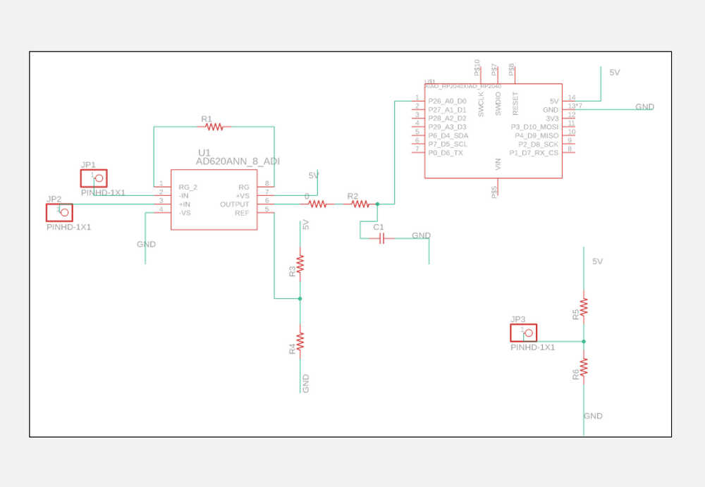
My design included a way to cutout the frequencies that are definitely outside of the reasonable range, however, signal was still hard to read. Sometimes it worked and I could see a little bit of signal on the screen of the osciloscope.
Since the system was occasionally working and occasionally not, I verified for myself that the design is approximately right (with maybe some of the resistor values to be adjusted), and I could go ahead and design and mill the board, so that I get more reliable results. -
EMG: Designing and milling
After a few boards designed over the course of the semester, milling one more felt easy. I still got to struggle a little bit since the milling machine I used before was taken, and I needed to learn how to use a different one, but overall it wasn't an issue.
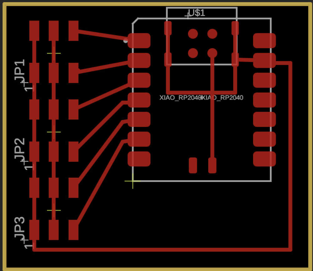
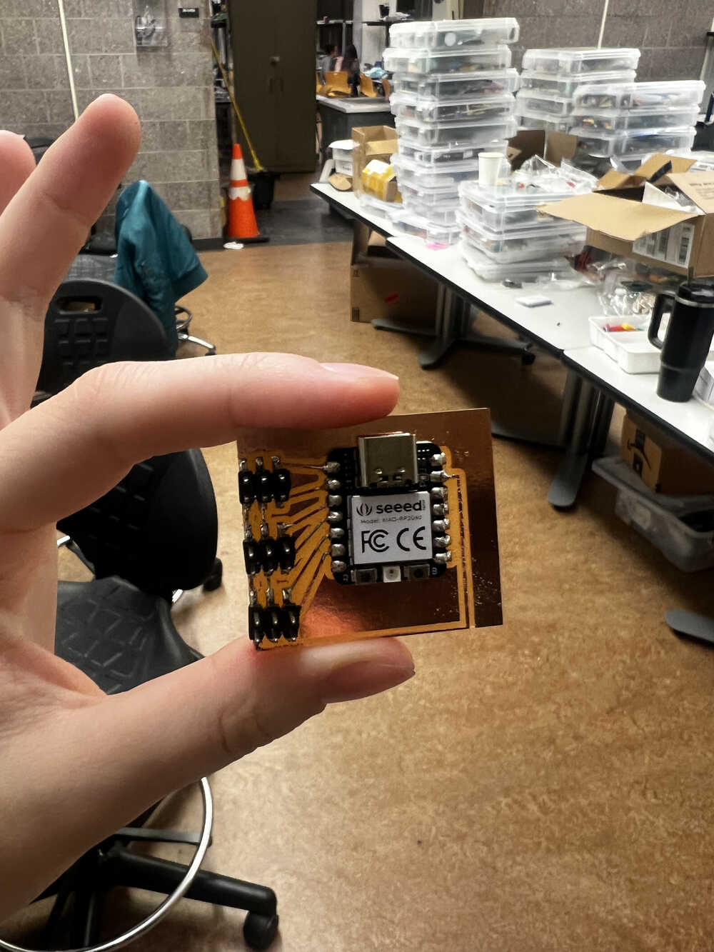
The manufacturing file can be found here, with an approximate screenshots being on the right.
The printed board and soldered board pictures are also on the right. On this step, however, I already had a few oopsies (which I would have corrected if I was remaking the project, but it didn't affect the functionality):
> Drilling holes ended up non-trival, a Gerber file that got fed into mods project ended up not having some of the holes, so I had to improvise with how to solder an OP-AMP.
> I chose an incorrect outline for the capacitor, so I had to use a blue one that is probably more intended for breadboards, instead of a small one.
> Also, I didn't really know that the pin holders are supposed to be soldered to the other side (I tried to fix it later, but it ended up being even worse because little parts of the connections were damaged).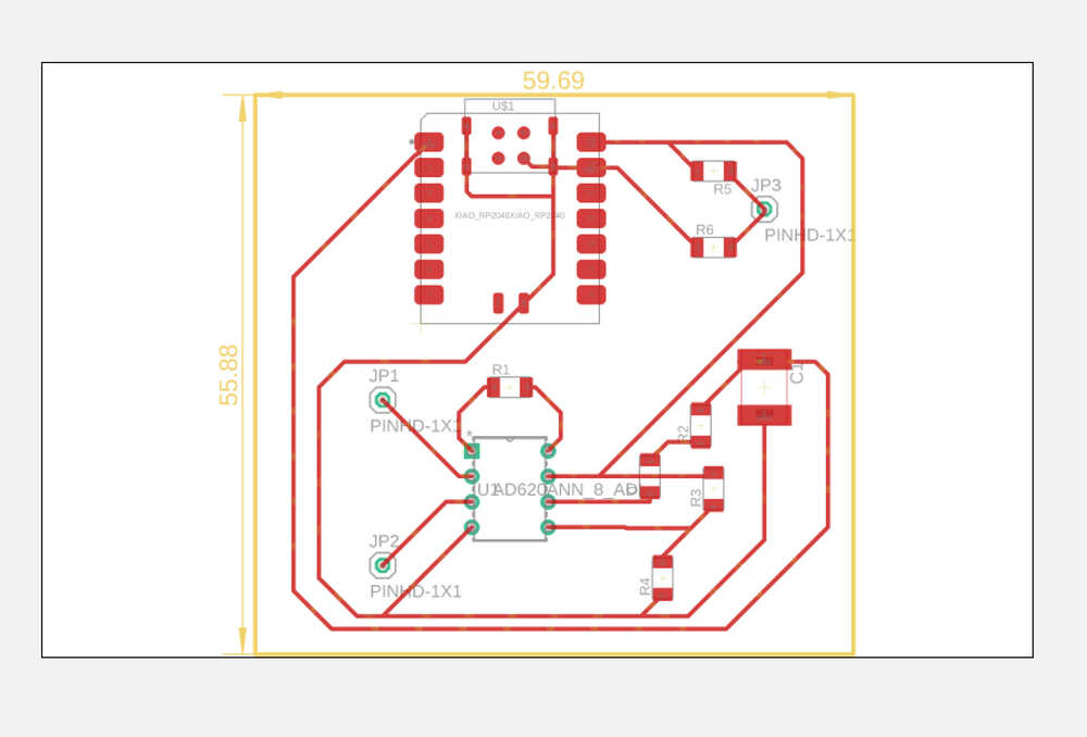


-
EMG: Testing
I have a lot of videos working and not working and trying to make it work. Inconsistency of the results is explained by unreliability of the signal received from the muscle and connection gel drying out to some extent. The last video shows the time when the system was working, as you can see and hear how, when I contract the muscle, the signal grows, and then drops when I relax my arm. The difference is on the order of 250 for relaxed and 500 for contracted, although, of course, these values would vary for different muscles, contacts, and people.
The "coin" system was replaced with a third (black) connector, mainly for the ease and consistency of the connection. -
Control V4: Application Interface
An attempt to set up EMG as a way to control my hand was great, however, unreliable. I wanted to design a different way to control the hand that would be easier to control and more consistent.
To achieve that, I iterated on the idea of controlling the hand through a computer interface, that was introduced in week 11. The main idea was to have a computer interface that would allow me to control the hand by pressing buttons on the screen. In week 11 I only achieved control of one finger, so I expanded control system to all fingers.
The video on the right is a demonstration of controlling one finger through an interface. As you can see, it works pretty reliably, but only controls one finger. However, let me cycle back on the process of making. -

Control V4: Application Interface (continued)
My biggest reference resource was this Medium post that builds a simple GUI for controlling an LED (only two states to handle). I mainly reuse the code from the article, while adapting it to my microcontroller and application.
It's pretty easy to adapt the code, the only points to worry about are the pins, serial port. In my case serial port kept changing every once in a while, so I had to retry sometimes if it flipped. For example, it could switch from '/dev/cu.usbmodem14101' to '/dev/cu.usbmodem14100' and back, but not every run, I imagine it has something to do with my computer communicating with microcontroller and establishing new connection.
So the order of setting up the system is first launch the Arduino code (which is a code that awaits for a byte from Serial, and then decides what to do based on the byte being received). Sending just one byte is convenient, but it looses descriptiveness of the variable names (I just ended up sending 'A', 'B', 'C', etc., which is regardless just a backend notation, and doesn't interfere with user understanding, but it is not very descriptive for the programmer).
Crucial idea of the Arduino code is to get byte from Serial (incomingByte = Serial.read();) and then write to servos based on that. Complete code for the Arduino can be found here.
Now talking about Python code. It relies on Serial to communicate with microcontroller and tkinter to make a GUI. The main idea is to have a button that sends a byte to the microcontroller, and then the microcontroller does something based on that byte. Serial library establishes connection (ser = serial.Serial('/dev/cu.usbmodem14301', 9600)), which is why you need to launch Arduino code first, to know which exact connection to establish. Then you can send bytes to the microcontroller (e.g. ser.write(bytes('L', 'UTF-8'))). Complete code for the Python can be found here. -
Results and Summary
And this wraps up an MVP for the project. The system is able to move fingers, and it is able to be controlled through a computer interface. The system is not perfect, and there are a lot of things that could be improved, but it is a good start.
A few more notes about the project. It was a lot of work throughout the semester (and I am writing it as I am finishing up during IAP). I really appreciate help of all the people who contributed to my learning and project development, with special thanks to EECS TAs Anthony and Maaya and professor Gershenfeld. There was also a lot of learning and advice from other students, which I didn't expect and am very grateful for.
Now, I wanted to talk about the project presentation that I didn't get to give because I got COVID. There was a very extensive checklist posted on the website regarding final project presentation, so let me iterate through those. -

Project Presentation
Q: What does it do?
A: My project is working on prosthetic systems which can also be described as a robotic arm. Its main goal is bieng able to move fingers and be reliably controlled.Q: Who's done what beforehand?
A: Section Background of this page gives a lot of references to the work that was done before. I was inspired by the work of Xu et al., talk with my friend who used to work at Biomechatronics group at MIT Media Lab, and following Superhumans - a recently opened reabilitation and prosthetics hub at Ukraine. Their CEO is sharing a lot of insights on importance of high quality prosthetics but also reabilitation process. The main takeaway was that there is a wide range of prosthetic systems, with key factors being cost, comfort and personalization, and that there is a lot of work to be done in this field.Q: What did you design?
A: This whole page described my design and manufacturing journey, but to keep it brief - I designed several iterations of the body of the robotic hand (3D printed and lasercutted), PCBs for control (EMG and Application Interface) and actuation (Servo Motors), and a computer interface for control (Interface).
My manufacturing files and code is linked along the description of the process and duplicated at the very end of this page.Q: What materials and components were used? Where did they come from? How much did they cost?
A: My answer would definitely vary depending on whether I need to count the ones which were used for development, or just the final product. Let's add the R&D costs to the final product costs and assume that tool usage was free (which is definitely not the case in real life, but also just putting the price of the whole machine doesn't feel reasonable). Here is a spreadsheet with the cost and approximate breakdown. The most pricy ones were clear acrylic, microcontrollers, servos, bolts, but overall it all summed up to 85$, which is pretty good for a total price of the product. ALL of the coponents listed above came from the EDS lab, which was very convenient. -
Project Presentation (continued)
Q: What parts and systems were made?
A: The physical structure of the robotic hand, actuation system (servos), two PCBs, Arduino code, EMG system, and a computer interface.Q: What processes were used?
A: I used 3D modelling, 3D printing, 2D modelling, laser cutting, milling, soldering, coding, assemblying, debugging, and testing.Q: What questions were answered?
A: My main objective was to dive into prostetics as a system, and understand what are the bottlenecks and how does the whole process work together. The few other questions were:
1. Can I use artificial muscles to control the system? In my head I was considering amplifying the muscle signal, so that maybe the thread gets heated enough but to the safe temperature, and flexes muscles. Didn't work, main reason: too slow.
2. Can I use EMG to control the system? I was hoping to get a signal from the forearm, and then use it to control the system. I was able to get a signal, but it was weak and unreliable. So I kinda can, but I needed more careful denoising and maybe EMG sensors.
3. Can I use a computer interface to control the system? Yes, I can, and it is reliable and easy to use.
4. Can I use just 5 servos to actuate the hand or do I need all 10? I was able to use just 5 and design it so that it was enough.Q: What worked? What didn't?
A: Final design worked. Controlling hand from GUI worked. Using EMG didn't exactly work. Using just 5 servos worked. 3D printed model didn't exactly work but probably can be iterated on.Q: How was it evaluated?
A: The final demo was an evaluation of my work. Can I actually control all the fingers of the hand in some way? Yes, from the GUI I designed.Q: What are the implications?
A: I am actually curious to talk to Biomechatronics group to see if they have any use for my system. I think it is a good start for a prosthetic system, and I would be happy to see it being used in some way, although I doubt that it has anything drastically novel. It feels at this point that it was a great time self-learning, but for more global impact I should rather join an existing prosthetic project than make one from scratch.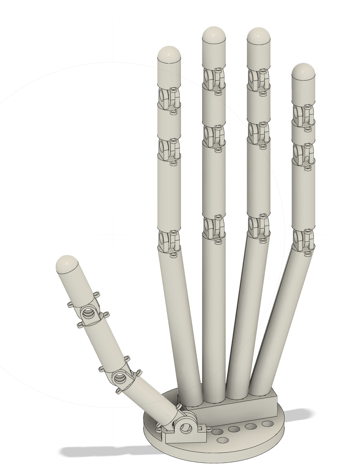
-
Project Presentation (continued)
Q: Prepare a summary slide and a one minute video showing its conception, construction, and operation.
A: Please find them linked here: Summary Slide, Demo, and Final Presentation, and at the right.
Q: Your project should incorporate 2D and 3D design, additive and subtractive fabrication processes, electronics design and production, embedded microcontroller design, interfacing, and programming, system integration and packaging.
A: 2D design was for lasercutting, 3D design was for connectors from fishing lane to servos and one of the first iterations; additive fabrication was 3D printing and subtractive process was lasercutting and PCB milling; electronics design and production was for EMG and servo control; embedded microcontroller design, interfacing, and programming was for servo control and computer interface GUI; system integration and packaging was embedded in a course of development, but it was probably linkage from making servos move to incorporating them in structure, and constructing a communication computer interface GUI; making slots for servo motors is part of packaging.
Q: Where possible, you should make rather than buy the parts of your project.
A: I made all the parts of the project, except for the servos, sensors and microcontrollers, which I got from the EDS lab.
Q: Projects can be separate or joint, but need to show individual mastery of the skills, and be independently operable.
A: I did the project individually.
Q: Present your final project, weekly and group assignments, and documentation.
A: This website is probably the most extensive documentation of my project except from my head :) Please let me know if anything is missing or confusing - I am trying my best to keep it up to date and very detailed for easy reference in the future. -
Manufacturing Files
Finally, I just wanted to link all the manufacturing files together so that it is easier to access them.
- 3D printed iteration of the hand (STL)
- Laser Cutting DXF (fingers)
- Laser Cutting DXF (base)
- Laser Cutting DXF (forearm)
- Servo connectors to fishing lanes, STL
- Servos Xiao-RP-2040 BRD file for PCB
- Arduino File that controls servos when launched together with GUI
- GUI Python code (for interface control of fingers)
- EMG Fusion File for circuit print
- EMG Arduino Code for reading signal