Macro-scale Fabrication
Two different explorations with the ShopBot
Exploration 1: Surface Milling
See a tutorial for 3D machining with the ShopBot
Having worked with the CNC and Waterjet cutter before for doing 2-D shapes, I decided to try to use the CNC as a 3-D device. The toolpaths were generated from an STL file, instead of a DXF, and we had to figure out some settings like steps in X and Y and Z. (Thanks Tom Lutz and Pete Schmitt).
The source file was an STL exported from a Rhino Model. The model was a mesh obtained from a set of irregular curves.
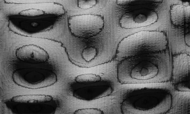
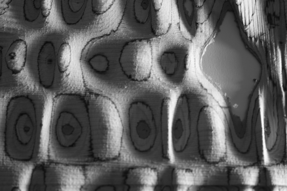
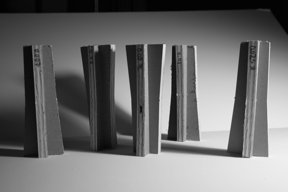
The plywood is a layered material, when milled its composition is revealed, and glue layers, as well as the different directions of the veneer layers.
Accidents and contingencies such as the warping of the plywood cause the bit to affect differently the surface of the material. In the image above two distinct resolutions are visible. This ahppens because of slight changes in the height of the plywood sheet, dure to warping.
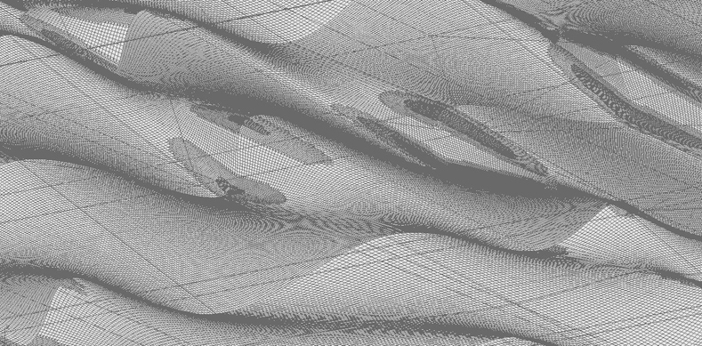
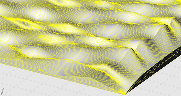
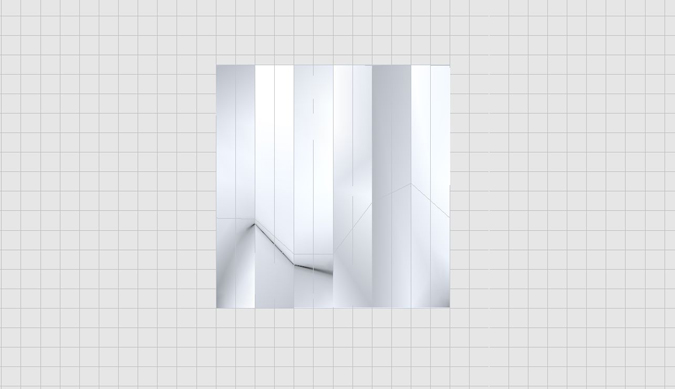
This image shows the high-resolution mesh exported from Rhino as an STL.
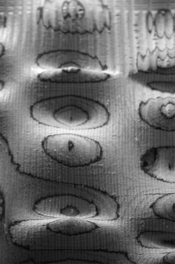
I made several studies changing variables such as the size of the X and Y step (from 50% on the first explorations to 27% on the latter ones), and the size of the bit (1/8 and 1/4). Some results were unexpectedly interesting.
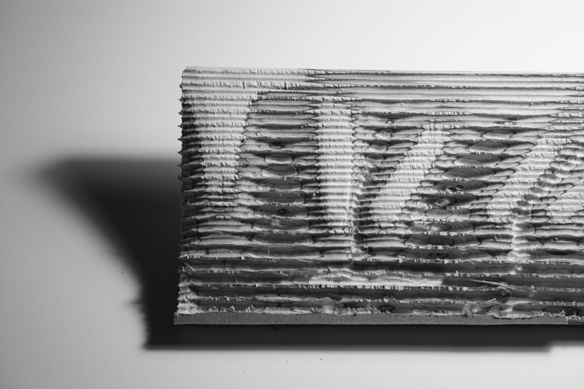
This unexpected result was not on the original file. There are small 'arches'. I only let the machine mill in one direction to preserve the latyers of wood that were aligned to the X axis. This was milled with a 1/8 in end bit. (The source file is the same as the previous surfaces).
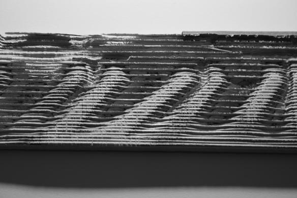
The differences in the direction of the veneer layers also has interesting consequences on the resulting milled surfaces. When exaggerating the XY step in the machine, very thin bridges of veneer remain after the X cuts (the remaining upper layer of veneer was aligned with the X of the cuts). This generates arches when the other layers of material (the ones that are not aligned with the X) are removed by the bit.
It is time to let go of the claim that the digital is precise and perfect. In this case the accident became the most interesting part.
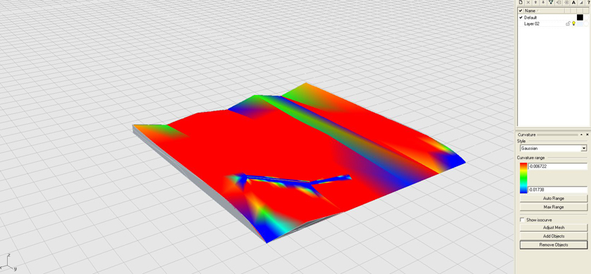
This was the first exploration, a surface in Rhino is analyzed in terms of its gaussian curvature. I tried to evelop surfaces that displayed different conditions.

Note: Appropriation by designers of digital fabrication machinery results in a new kind of engagement with materials and technology, a new kind of craft, a Generative Craft.
The differences with the digital file are so great, the accidents so rich. ShopBot is fun.
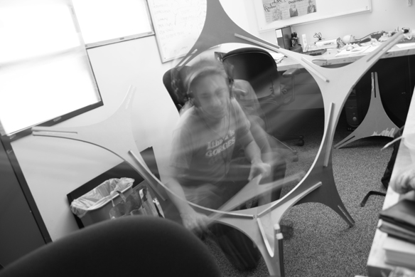
Exploration 2: XXL Melnikov Spaceframe
See my previous studies on Melnikov Press-Fit Kit
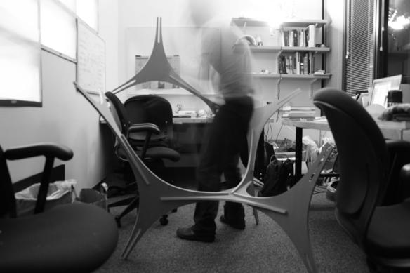
I couldn't resist doing the XL version of my Melnikov SpaceFrame. I cut 9 modules, which came from 3 pieces of 48x48 plywood (I used a part of one of these for the surface milling studies above).
Before cutting the final pieces I did test joints with different tolerance values. I wanted the pieces to be tight, but not so tight that you couldn't pull them apart and re-configure them in different ways.
I think that this system could be used as a structural module for certain circumstances. The rigidity of a system built with the Melnikov Space Frame should increase as more modules are added (because every modeule introduces new constraints in the system). The modularity makes it useful for complying with irregular contexts. Can the deployment of a large number of these objects be used for providing support for a flooded area? I want to perform FEM modeling on these. Stay tuned.
|