Milling the Fab ISP Board
Step 1: Milling
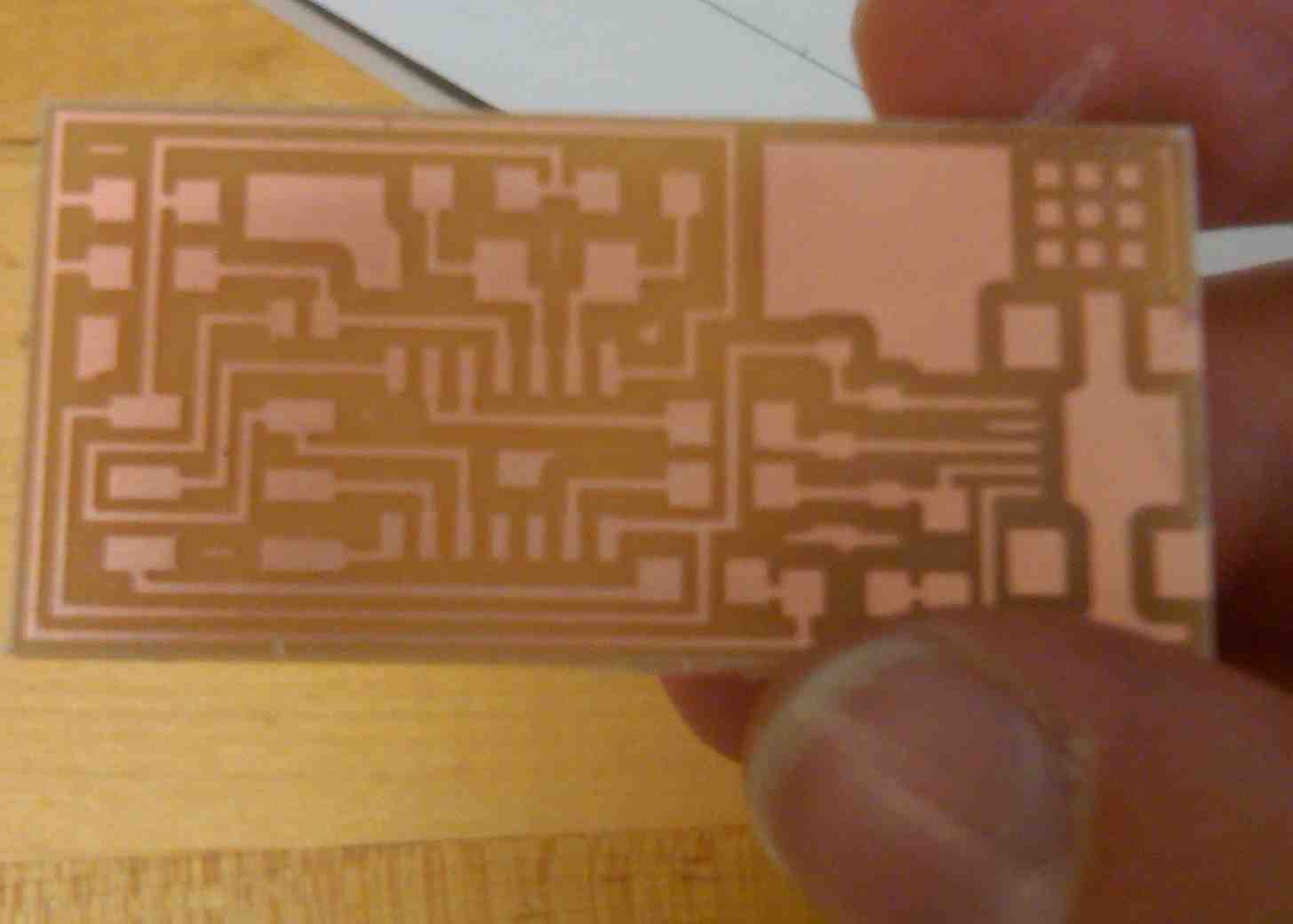
I milled the Fab ISP circuit board on the Roland Modela desktop milling machine.

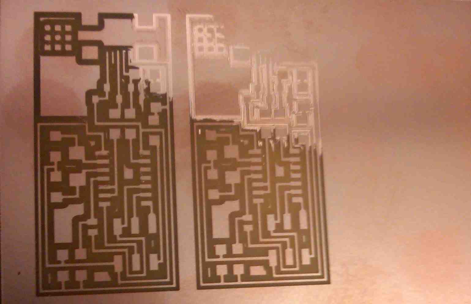
We (Akane and myself) initially tried to mill two boards at once, and after the job completed we discovered that there was a region in the upper right corner (high X & Y) that did not mill properly - there was some indentation, but the endmill did not penetrate through the ccopper. We initially thought this was a result of either lack of flatness due to poor placement of the double sided tape used to hold the board in place (this was not the case), or misplacing the 1/64" endmill used to cut the traces. Repeated reinstalation of the endmill multiple times did not resolve the issue.

We concluded there may have been bowing of either the board we were milling or the base board used as a guard. We moved the board we were milling to another part of the bed that was protected by another board, and were successful in milling the board traces and cutting the board out (cut out completed using a 1/32" endmill).

Step 2: Stuffing
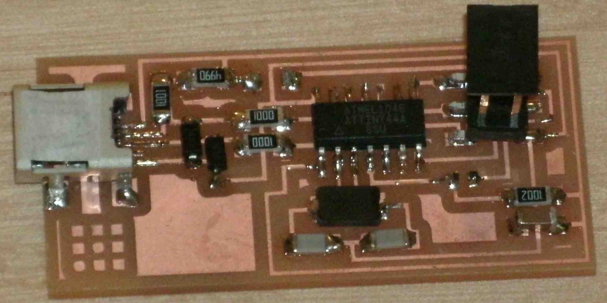
The milled board was washed with soap and water and stuffed with the necessary components. For the microcontroller, I soldered each foot individually, but for the USB port, I soldered all the legs together and wicked away the excess, which made for low-profile junctions.

Step 3: Programming
The initial attempt in programming the device failed at the 'make fuse' command. Upon checking the board, I observed what seemed to be a poor connection across one of the 100 ohm resistors (top 100 ohm resistor, from the perspective of the image above). Upon removing the resistor from the board, it did not seem to be functioning properly - likely due to an internal defect or due to damage from excess heating. Replacing the resistor allowed me to complete the programming of the board. After removing the solder junction and the 0 ohm resistor, the board was recognized as Fab ISP by the computer.