electronics production:
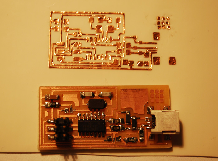
This week, I made a PCB from scratch, from milling to stuffing to programming. More specifically, I made a FabISP: a fab-able in-system programmer!
There are several ways to make a printed circuit board. The most common ways to make a circuit are etching and machining. Etching requires a chemical process that creates waste that if not thrown away properly, can eat away at metal pipes and other materials. I decided to try milling and cutting.
The Roland Modella and the vinyl cutter:
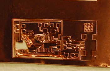
Milling:
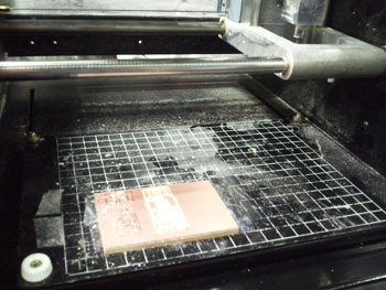
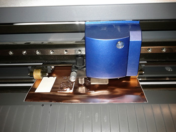
I used a Roland Modella CNC Mill for our circuits. We started with an FR1 copper plated board. There are two types of boards that are commonly used. FR1 is made our of phenolic paper, and FR4 is made our of epoxy glass. When machined, the epoxy glass can cut your skin, and is very dangerous if inhaled.
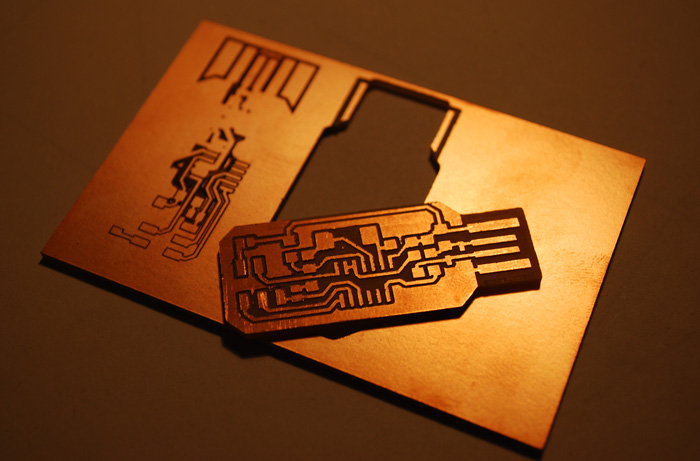
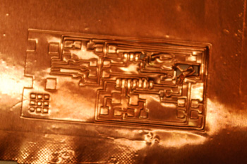
To make the traces of the circuit, I milled away the copper with a 1/64 inch end drill. To cut the board out of the original board, I used a 1/32 inch end drill. Since cutting out the board requires cutting though the board, there should be another board beneath it to prevent drilling the bed of the Modella. Both of these should be securely fastened with the amazing Scotch double sided tape. First, place the scrap board orthogonally on the bed near the bottom left corner, which is the origin of the machine. Then, place the board that will become your circuit on top of the scrap board, also alligned orthogonally.
There are three main settings to consider:
- The x-min and y-min values. These values will define the "origin" of your design. I found these by estimating values based on the grid on the Modella, where each square measures 1 cm on each end. I then found the perfect spot through successive approximation. Here, I set my relative origin at x = 25 mm, y = 15 mm.
- The zero in the z direction. This is crucial, because your depth of cut depends on the accuracy of this value. To set the zero, it's best to set it in the center of the board, since they corners are more likely to bend upwards. First, with the end drill as far up the chuck as possible, lower the z-axis witht he arrows on the Modella. Bring it down to about a quarter of an inch form the lowest possible position. Loosen the set screws, and gently lower the end drill to prevent any damage Lowering it with a finger helps to make sure it doensn't fall and break. Tap it gently against the board a few times to make sure there is no dust in the way and that you have a true zero. Now tighten the set screws evenly on both sides to hold the end drill in place and to ensure it's perfectly centered.
- The depth of cut. For the traces, the recommended value was 0.1 mm, since it tou only need to cut through the copper. After experimenting, I ended up using a depth of 0.15 mm for my traces. Keep in mind that this value can change depending on the quality of the end mill. To completely cut out the board, the depth of cut should be about 1.7 mm, since the board is 1.56 mm thick.
The rest of the setting were defined in the appropriate defaults of the fab modules. These included the allowed error and the number of passes.
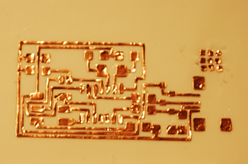
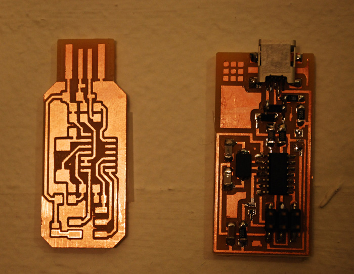
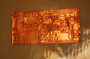
File prgression: I started out with the FabISP pngs that were provided in class. Using the fab modules, I created a path from the PNGs, and once I had the right settings, I created a .rml file, I sent it to the Roland Modella. These PNGs were exported from Eagle, which I will use in the future to design my own circuits.
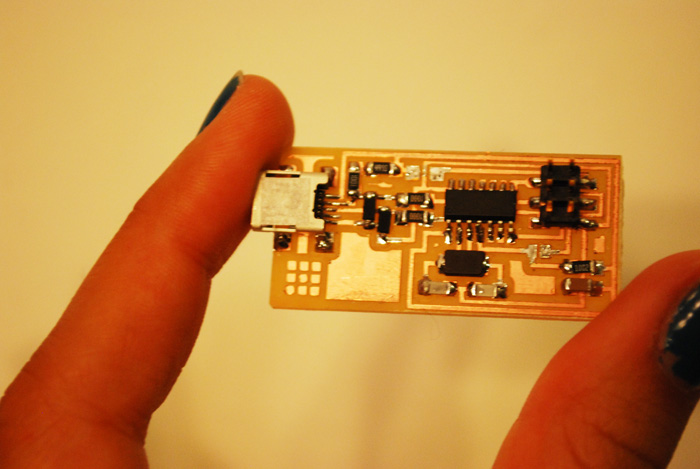
New design:Andy Bardagjy, a fellow classmate, took the initiative to redesign the FabISP board, and made is so that the PCB plugs directly into a computer's UBB port! I was very impressed. I wanted to try his design, so I also made it on the Roland Modella. I used the same settings I used for the original design. I ended up only stuffing the original board, becuase I wanted to really understand how it worked before I moved on to a different design.
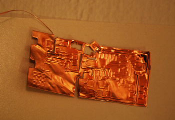
Cutting:
I was also very eager to try the vinyl cutter to make circuits, since the cutter provides more flexibility and a cheaper way to experiment with different circuit designs. This week, I only tried the FabISP deisgn.
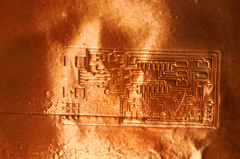
As usual with the vinyl cutter, the biggest challenge was finding the right settings, since they change each time depending on the blade, the material, and the cutter's temper. the recommended settings are a power = 55 and speed = 2.5. Afer many attempts, I finally settled on power = 80 and speed = 2. Again, I used a PNG files and the fab modules to sent the command to the cutter.
power = 55
speed = 2.5
These were the default settings, but they only marked the copper tape. The blade did not
cut through the copper. I definitely needed more power.
power = 70
speed = 2
I made two passes with these settings. The first time, I wasn't sure if the blade had actually
cut through, so I ran it a second time. The result was only through cuts in some places.
power = 85
speed = 0.5
I increased the power and slowed it down. This time I ran into a new problem. The cut was enougn
to easily take apart the pieces, but this time, because the pieces were loose, some of the smaller
pieces got stuck to the blade and were pulled off the adhesive.
power = 70
speed = 0.5
To prevent this pulling off, I decreased the power a little, but kept the speed the same. Again,
the blade pulled off some pieces.
power = 80
speed = 0.5
But overall the cuts were great. They were just the right depth. So I increased the power to a value
in between my last two attemps. I noticed that the tape was bulging a little, which was a result of
careless setup. Sure enough, toward the end of the cut, some of the small peices stuck to the blade
and came off the tape.
power = 80
speed = 0.5
Same settings as above, but making sure the tape was flat and taught between the two rollers. I was
satisfied with this cut, so I used double sided tape to transfer it to epozy tape, which is heat
resistant. But it turned out that the traces were really hard to separate.
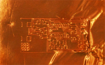
power = 80
speed = 2
I realized that I hadn't adjusted the speed in the last three cuts, so I increased the speed to 2.
Finally, these settings worked very well. Using tweezers, I was able to painstakingly remove the
unwanted copper tape, leaving behind a perfect circuit. I felt like I was playing Operation,
a game that lets pretend they are surgeons! I didn't stuff this one, since I wanted to
attempt it mainly to practice cutting circuits on the vinyl cutter.