The MicroCritters:
This week, I beautifully executed a very complicated way of doing something very simple.
The triumph:
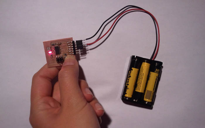
I made a new PBC, which I designed in Eagle, stuffed it, and programmed it so that when you push a button, an LED turns on. Awesome, right? I felt incredibly accomplished when I finally got it to work.
The silly realization:
Then I realized that I had spend hours (and very many of them) doing something that would have taken me a maximum of 10 minutes to make with some copper ribbon, a 3V coin cell, and a basic 5mm LED. My beautiful PCB circuit turns on an LED when the button is pressed, which I can easily recreate it but connecting an LED and a coin cell with copper ribbon, or even just wire, and cutting it somewhere to create a mechanical switch, which would be turned on by physically joining the cut pieces again.
The unyielding pride:
Nonetheless, I am incredibly proud of my board. The process was an adventure that taught me so much. I learned to use Eagle to design circuit boards, I learned the fundamentals of coding in C, I learned how microprocessors work and what all the pins do, I got more practice making and stuffing boards, and I learned how to upload a program to my board by using the command line. Wow. I know.
The adventure:
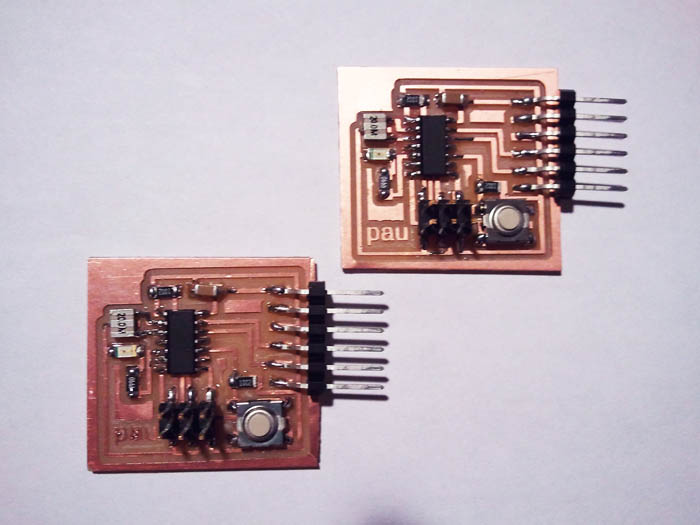
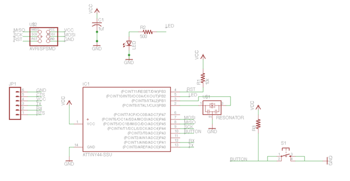
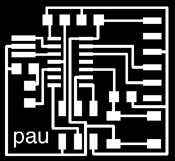
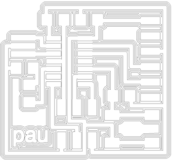
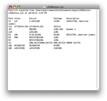
I started out by designing my circuit. I started with a template that maps out the basics of all our boards. I contained the AVR Tiny 44, a 2x3 pin header, a 6-pin FTDI header, and a 20 MHz resonator. I added an LED, a switch, and a couple resistore here and there to the schematic. I added the components from two libraires- the fab library and Neil Gershenfeld's library (ng). Then I routed them in the board and checked that all my connections were good and that I hadn't crossed any wires.
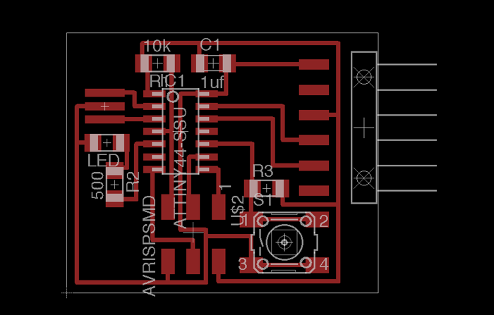
I exported the board as a monochrome PNG and was ready to tackle the Roland Modella. I had had some trouble with the Modella while making my first PCB, so I allowed myself two hours to complete the milling. But the process was perfectly smooth. The biggest problem I had was not finding any double-sided tape to hold my board down with. The milling was so flawless that I was so pleased that I made a second board.
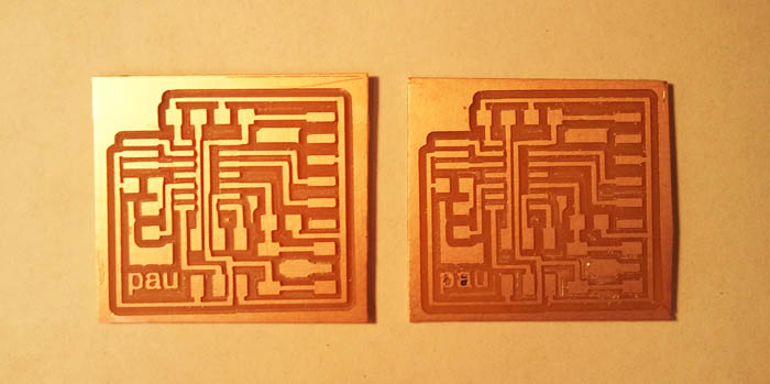
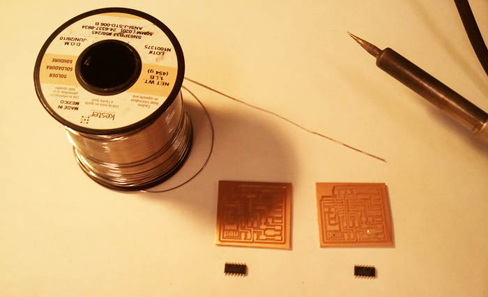
Then came the stuffing. I was much more systematic about it this time around. I coppied my bill of materials (which I got form Eagle) down on a piece of paper. I drew a box for each component, labeled it, and write down the quantity I needed. As I collected the components, I places them in the respective box on my paper. Because I was stuffing two boards, I stuffed both boards in parallel (get it? haha!).
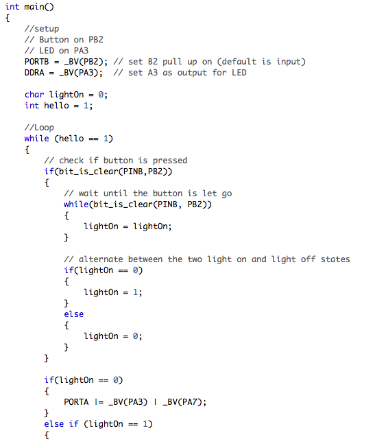
Then came programming. This was tough. After reading through many tutorials and examples of microcontroller programming from previous years, I decided that the best process would be to write my program in C from a text editor and use the Make program from terminal to write it to my board. I also had to install CrossPack, a development enviromnent for AVR. Once I had my C program, which I modified from the hello.ftdi.4.echo.c file on the class page, I used the .make file, also from the class page, and edited the project name to be the same as my .c file name. Here's a screenshot of the important chunk of my code (after many #define statements):
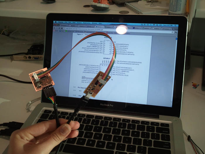
I used the FabISP I made the second week of class to program my board. I connected it to my computer with at mini USB cable, then connected the FabISP to my new board with the rainbow cables we also made (connects both boards via the 2x3 headers), and connected my new board back to my computer with and FTDI cable for power and serial communication. Then from terminal, I used three commands to upload my code:
- make -f hello.ftdi.44.echo.c.make
- make -f hello.ftdi.44.echo.c.make program-usbtiny-fuses
- make -f hello.ftdi.44.echo.c.make program-usbtiny
And voila. A really complicated way of making something very simple. But now all I have to do is edit my code to make it do something really cool. Stay tuned!