charlieplexing
This week I was fascinated by the idea of charlieplexing. I explored it by making Neil's board and changing the code, and by completely redisigning the layout of the circuit to place all the LEDs in a straight line. I also made my first complete vinyl cut circuit, which was quite a ride.
First, I just milled Neil's board to understand how charlieplexing worked. Everything went very smoothly. The only problem I had was that when I uploaded my code, the first LED of both the first row and the second row were off. After some quick examination, I found that my first LED was not touching one of the pads. As soon as I fixed this, my board worked beautifully. Check it out:
HELLO WORLD!
Then I started researching to learn more about charlieplexing and what you could to with it. I found several examples, but what I liked the most from each example was the circuit board itself. So I decided to make something that would both let me learn about charlieplexing an allow me to make a beautiful , elaborate board. So I decided to find a way to lay out the traces such that all the 20 LEDs were in a straight line. I essentially took the second row and moved it to the right of the first, took the third row and moved it to the right of the second, etc. I tried re-routing them in Eagle, but aside from it being very messy, I didn's have enough space in Eagle to put them all in a line. So then I totally scratched the eagle idea and pulled out some papaer.
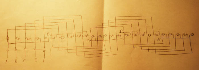
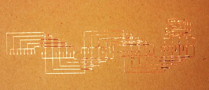
I drew the 25 LEDs (from 5 by 5 array) in a straight line. Starting with the first LED, I drew a line from that one to every fifth LED. I did the same for the seocnd, third, fourth and fifth. So I ended up with allthe rows interspersed. Then connecting the columns was easy. Since the first 5 LEDs were all on different rows, I just drew at straight line through all the dots. I was first using dots to represent LEDs, disregarding the polarity. Once I had the general layout, I took away the LEDs that would have fallen on the diagonal and drew a small schematinc of what each dot looked like, which was a small square with an LED on one of the sides. Becuase I didn't have enough space in Eagle, I created my board on Illustrator. I used Neil's board to reference the size of the pads, the sizes of all the components, and the thickness of the traces. They layout was simple and beautiful.
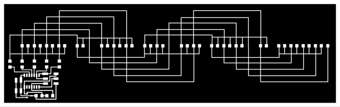
take 1:
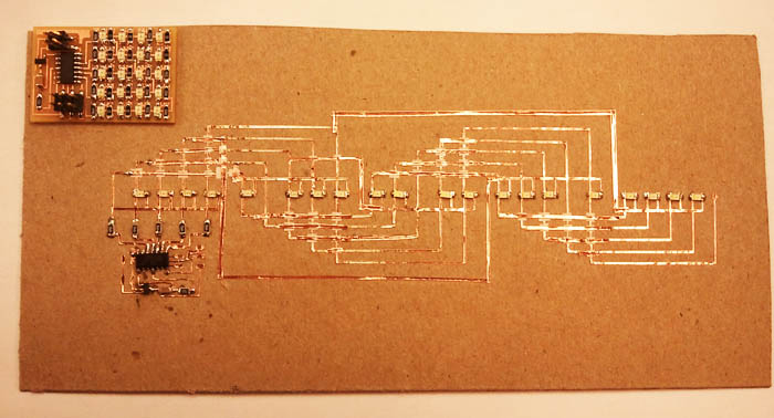
take 2:
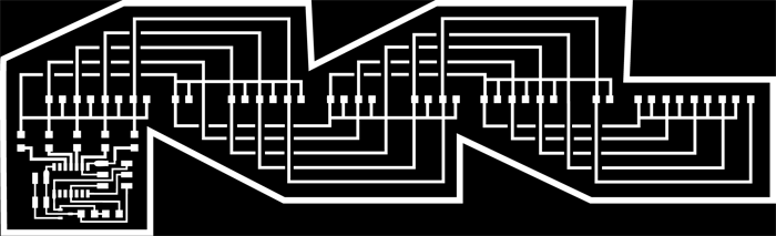
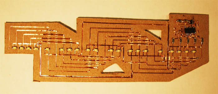
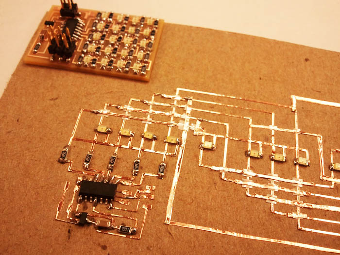
Then came vinyl cutting. Theodora had just finished weeding, and her board looked great, so I asked her for the settings she had used and tried those first. I ended up simply using the default settings: Force= 55 and speed= 2.5. I the first complete cut I tried to weed proved difficult and practically impossible to complete without riping up some traces. After ripping about 10 traces, I went back to Illustrator to redesign the board. I made the traces a bit thicker and cut out where I was going to place epoxy to separate the two layers of the board, which I had planned on doing manually in the first iteration. This was relatively easy to weed. Time consuming because it was a large board, but the pieces separated easily and barely any traces ripped. Once I was done weeding, I placed a small square of epoxy wherever I has two intersecting traces, and then placed copper strips above the epoxy. Soldering was smoother than I expected. The hard part was the programming. I didn't want to attach the headers, so I simply tried pressing them down on the board while programming them.