Input devices
Gyroscope sensor and a 2.4 GHz wireless module with atmega328
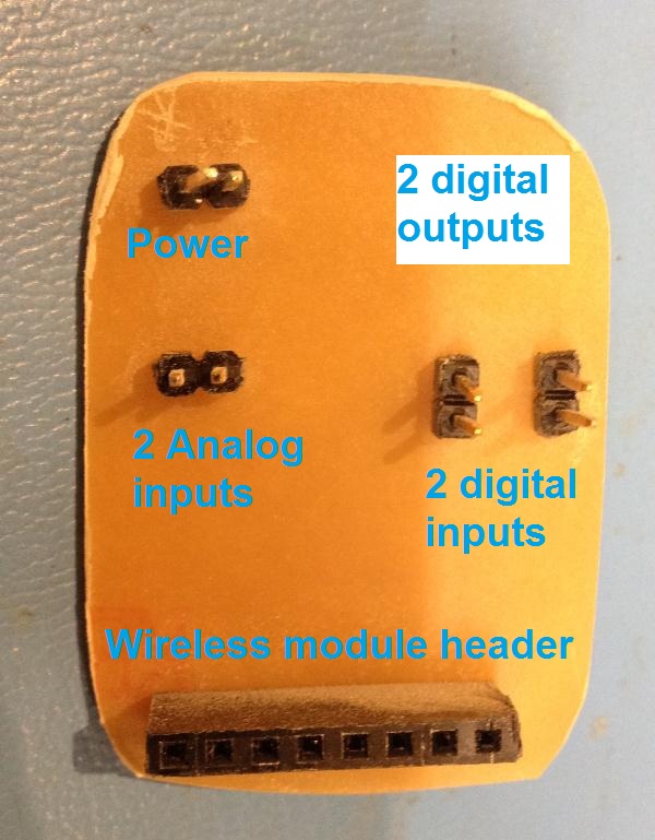
The microcontroller board is continued from last week with modifications including adding a 5v voltage regulator, two analog inputs, through-hole headers and also two pull resistors (10k) for the two digital inputs.

Traces
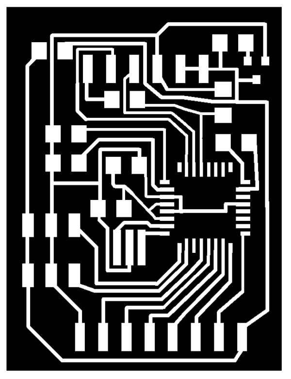
The board after milling in the Modela. For some reason two traces were still joined though in the design they weren't

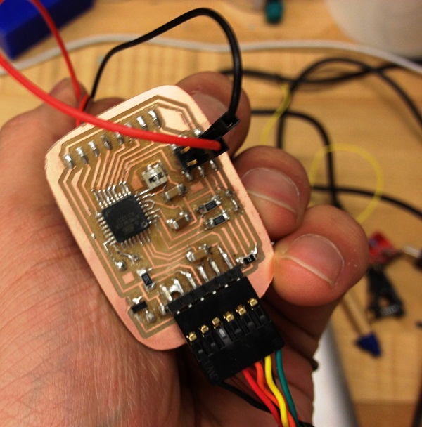
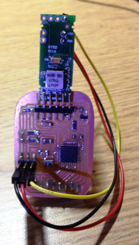
After stuffing the board. I used the heat-gun to unformily melt the solder for the atmega328; It took a good time to get the alignment right, then I applied the heat-gun for about 10 seconds while moving around to ensure that the heat has reached the four sides

and from the back. Last week I had the header on the surface on the other side but it kepts comming off after a few uses, so I decided to drill some holes this time to give more robustness to the wireless module header.
Burning the Arduino bootloader

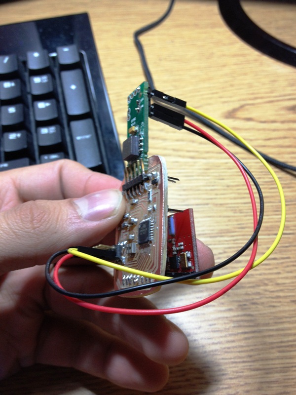
Checking the FTDI connection
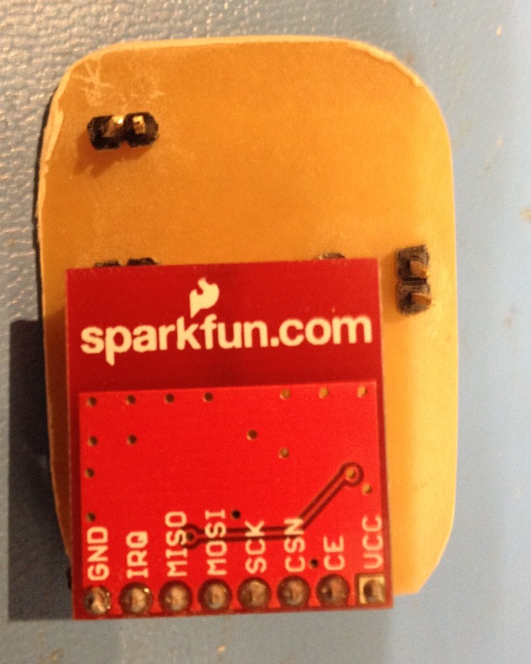
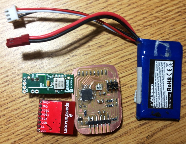
Finally, the Nordic Transceiver nRF2401A Module on a breakout board from Sparkfun fits nicly in the header.
The sensor
+-150/s Single Chip Yaw Rate Gyro with Signal Conditioning from analog devives.

The Datasheet for ADXRS150
The complete set ! now with two-cell Lipo battery that gives about 7.4 V but then gets regulated to 5v by the onboard voltage regulator
Testing..
Testing.
Note that the axis of rotation is the normal of the board
Realtime results from Receiver module every 200ms.
Note: the gyro appears to drift over time and the error starts accumulating. It could be that I was tunring my hand in a rate that was faster than what the gyro could sense, or it could be that the LSB constant (lsb_ms_per_deg) varies because of temperature and needs recalibration

The Receiver with another Nordic Transceiver nRF2401A Module on a breakout board from Sparkfun

Gyroscope calculation - numerically integrating the angular velocity to get the current relative angle or the heading.
							void gyro_init(uint8_t port, float lsb_us_per_deg, uint32_t time_ms) {
								uint32_t samples;
								uint32_t sum;
								uint32_t start_time_ms;

								_port = port;
								_lsb_us_per_deg = lsb_us_per_deg;

								// average some samples for offset
								sum = 0.0;
								samples = 0;
								start_time_ms = get_time ();
								while ( (get_time() - start_time_ms) < time_ms ) {
									sum += analog_read (_port);
									samples ++;
								}

								_offset = (uint16_t)(sum / samples);
								_offset_fix = (sum % samples);
								_fix_divisor = samples;
								_theta = 0;

								init_lock (&gyro_lock, "gyro lock");
								create_thread (&gyro_update, STACK_DEFAULT, 0, "gyro");
							}

							int gyro_update(void) {
								/* The units of theta are converter LSBs * ms
								   1 deg/s = 5mV = 0.256 LSB for ADXRS300, 12.5mV = 0.64LSB for ADXRS150
								   1 deg = 0.256LSB * 1000ms = 256 (stored in lsb_ms_per_deg)
								   To convert theta to degrees, divide by lsb_ms_per_deg. */
								uint32_t delta_t_us, new_time_us, time_us;
								int32_t analog_value, fix_value;
								time_us = get_time_us();
								for(;;) {
									analog_value = (int32_t)analog_read(_port) - _offset;
									new_time_us = get_time_us();
									delta_t_us = (new_time_us - time_us);
									int32_t dtheta = analog_value * delta_t_us;

									fix_value = _offset_fix * delta_t_us;

									/* This does the Riemann sum; CCW gyro output polarity is negative
									   when the gyro is visible from the top of the robot. */
									acquire (&gyro_lock);
									// accumulate fractional error
									_theta_fix += fix_value;
									// apply error correction
									// negative because _offset is subtracted
									// from dtheta
									dtheta -= _theta_fix / _fix_divisor;
									_theta_fix %= _fix_divisor;
									// integrate angle
									_theta -= dtheta;
									release (&gyro_lock);

									time_us = new_time_us;
									yield();
								}
								return 0;
							}

							float gyro_get_degrees (void) {

								acquire (&gyro_lock);
								float result = _theta / _lsb_us_per_deg;
								release (&gyro_lock);

								return result;

								float in;

								acquire(&socket_lock);
								write(sockfd, "a\n", 2);
								read(sockfd, socket_buffer, SOCKET_BUF_SIZE);
								sscanf(socket_buffer, "%f", &in);
								release(&socket_lock);

								return in;
							}

							void gyro_set_degrees (float deg) {
								acquire (&gyro_lock);
								_theta = deg * _lsb_us_per_deg;
								release (&gyro_lock);
							}