 |
||||||||||||
| HOW TO MAKE (ALMOST) ANYTHING MIT MEDIA LAB |
|
PROJECTS | ABOUT | CONTACT | ||||||||
|
|
|||||||||||
| EMBEDDED PROGRAMMING - week8 | ||||||||||||
|
|
|||||||||||
| The downloads and distributed knowledge | ||||||||||||
| Here are all the links that were needed for Windows 7 32 bit system. Took me a bit to collect the bits and pieces, so here it is consolidated: -FTDI drivers. -fabISP drivers can be found here -WinAVR C/C++ compiler -Arduino IDE -ATtiny44 . Find the file "ATtiny master.zip (hosted by GitHub)", download it, and follow instructions for extracting folders on either site. Previous years' knowledge I found useful: -JP 2013 -D 2012 -CF 2012 And these tutorials I found useful: -Charles 2013, where yet another student's work is mentioned. -HLT -difabs (the last two are also where you can download the ATtiny master zip file). | ||||||||||||
| Electronics Repeated | ||||||||||||
| Seems like most of the time I was actually perfecting my soldering skills rather than programming, as something was always wrong with the board. The way I knew that most of those errors showed up was that when I ran this command through the cmd terminal make -f hello.ftdi.44.echo.c.make program-usbtiny I got the somewhat standard error "initialization failed rc=-1" indicating that something is wrong with the hardware. I knew it was the LED board and not the fabISP because others in my section used my fabISP board to program their boards. | ||||||||||||
| The list of Hardware Problems | ||||||||||||
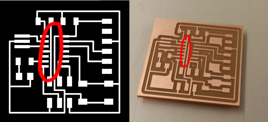
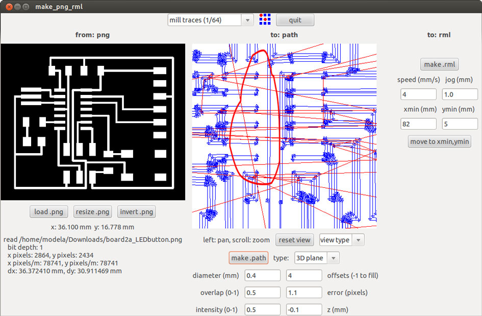
| Problem 1: Referring back to week6, the image below has something seriously wrong with it. I didn't catch it then, but it certainly wasn't going to work with all pins of the microprocessor connected to that trace. Problem was in the wrong settings in the fab modules - the space in between the trace and the pins of the microprocessor was too small for the traces to read. Lesson - check the trace carefully before milling. | ||||||||||||
 |
||||||||||||
| the board does not correspond to the .png image! | ||||||||||||
 |
||||||||||||
| and this is why | ||||||||||||
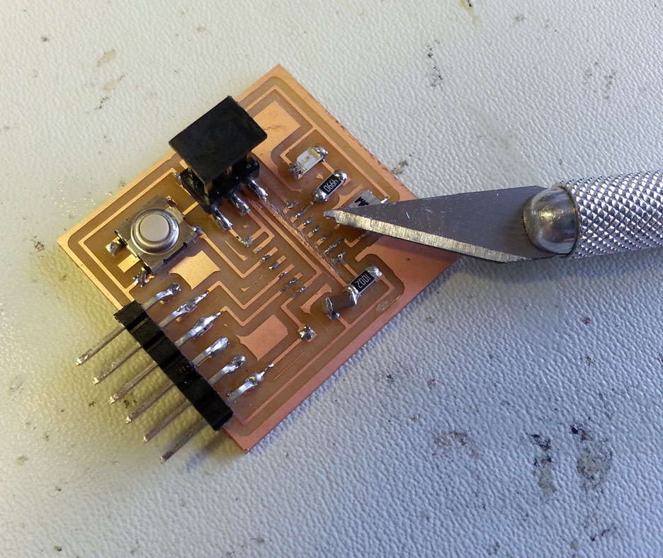
| I tried to just etch the copper away with an exacto knife that was supposed to be milled. | ||||||||||||
 |
||||||||||||
| razor brade makes up for what Modela missed | ||||||||||||
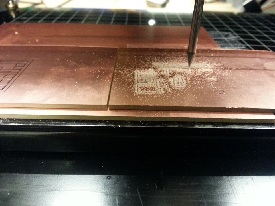
| It looked like I got the traces separated, but programming the board still didn't work, so I assumed it was shorting still. Problem 2: Look at the orientation of the microprocessor. As indicated in the HLT link above (and in the data sheet), the little circle (denoting VCC) should be on top left; ie, the little circle should follow the VCC line on the board, not GRD. I accidentally did it correctly when making FabISP the first time and consequently just didn't pay attention to orientation, though obviously the different pins of the ATtiny have different functionality, so it was senseless to assume them to be symmetric! Good to not accidentally do the same thing correctly twice. Problem 3: LED reversed. I knew this was soldered on incorrectly because when I powered my board via the FTDI cable, the light went on immediately having done absolutely no programming. Using the Voltmeter here to check whether the voltage across different parts on the board was as expected. **A(node) to C(athode), in alphabetical order, flowing towards GROUND** Problem 4: I still don't know if it was actually necessary, as some people's boards worked fine without it, but I was told that I would need to program something extra if I didn't put a resistor between the button and the microprocessor. So as I had to redo the board anyway, to be safe I put it in, though I am still confused about whether or not it is necessary and why. Problem 5: To avoid the issue with space between traces, I made another board after re-soldering the previous one one too many times, and I deliberately made the board a bit bigger, with bigger spaces and wider traces. This time the issue was with milling though, as for some reason it seemed like Modela was really not even in its depth across differet xy points on the plane. | ||||||||||||
 |
||||||||||||
| can somewhat see the unevenness in milling depth comparing right side and left side | ||||||||||||
| The board traces came out not very smooth, but definitely functional, especially after the ruler method. | ||||||||||||
 |
||||||||||||
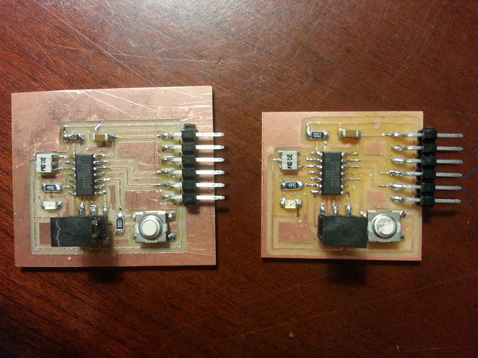
| the bigger one works, the smaller one suffered | ||||||||||||
| In all - I did a lot of de-soldering and re-soldering, learned the beauty of the heat gun for this purpose, but in the end made another board anyway, as there wasn't enough magic that was going to make the first one work. | ||||||||||||
| Finally to programming | ||||||||||||
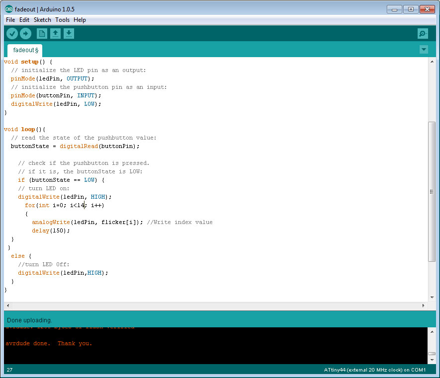
| I did end up switching to the Arduino, and found it a really intuitive environment. The JP 2013 example from last year got me started on the use of the button acting as a switch, after which I played around with fade a bit. The code from the Examples is very easy to combine and use, just remembering to change the pin numbers according to the data sheet. On this board, the LED Pin is connected to Pin 7 on this board, and the button is connected to Pin 3. For fade, I used the D2012 tutorial to get me started, and then played with code to only fade out from an already lit LED as opposed to changing it. | ||||||||||||
 |
||||||||||||
| Making rookie mistakes in C code, such as omiting semicolons and mistaking = (assingment) for == (test), and starting to understand the Array structure. Here is the video of those operations. | ||||||||||||
LED and button programmed in 4 ways.
| Copyright 2013 by Anya Yermakova | ||||||||||||