
Final Project Update!
Name: DRAW it!
Author: Diego Pinochet
Class: How to Make [almost] Anything (Fall 2013)


The Final project is called DRAW IT!. Since the begining of the semester i was curious about the idea of making a wearable that can sense something. Coming from an architectural background, i was intrigued by the idea of doing something more related to industrial design using my experience with digital fabrication and advanced modelling in the past.


In September i proposed a wearable that can recognize and sense some characteristics of objects through haptic feedback, sadly my absolutely null experience with electronics was an obstacle all the semester to acomplish that project, but i think that after this class i'm on the right track to make it in the next months.
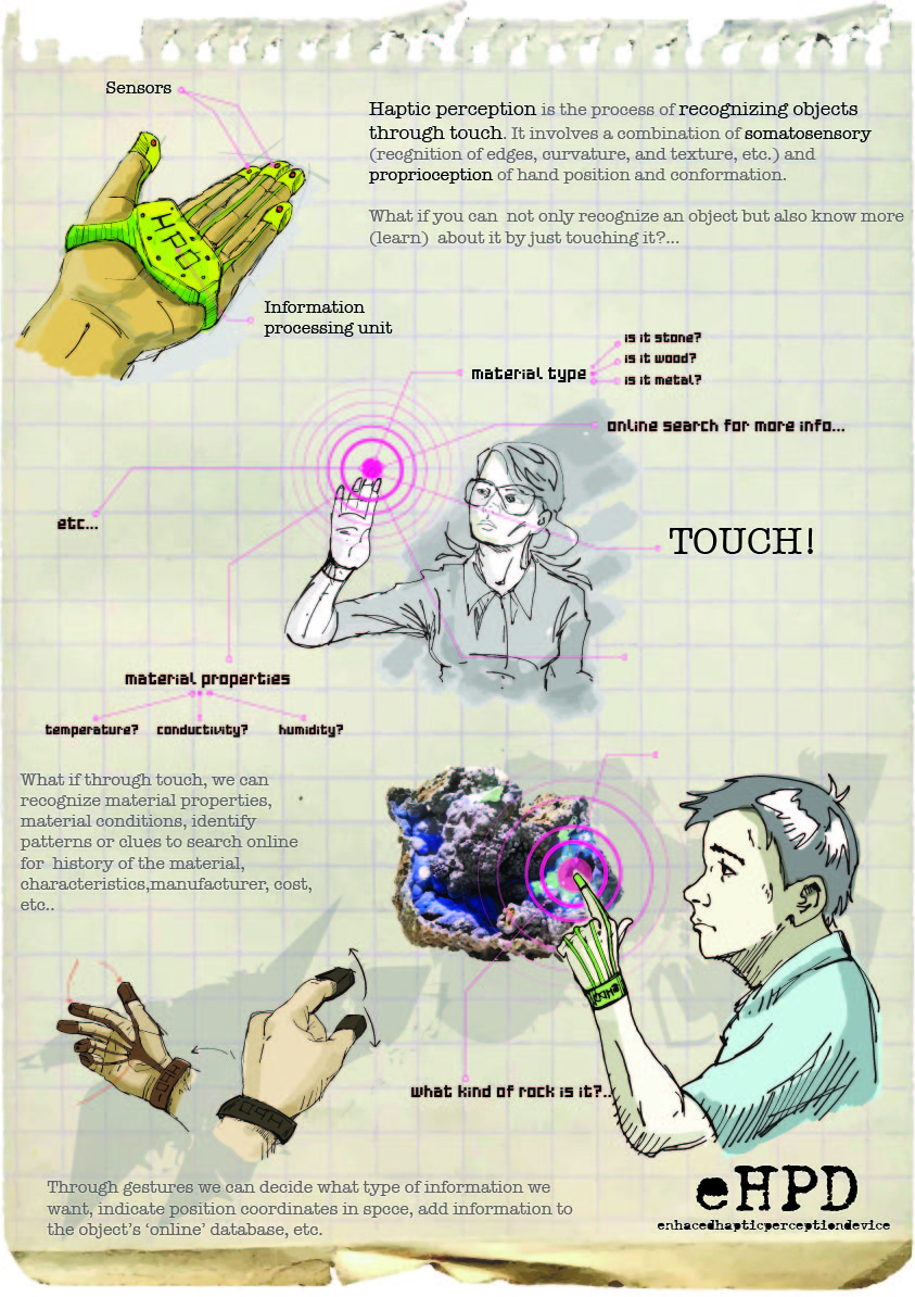
So, my project changed a little bit... since the embedded programming week i was interested in applying my new programming skills (i took course 1.00 (JAVA) with the amazing professor Kocur), so i started to play with the LEAP motion sensor. I started programming some simple programs with gesture recognition, etc. but i found that something was missing. all of this technologies such as Kinect , leap , etc. miss the touching part, they are very much like minority report...
I decided to stay with the idea of designing and making a wearable that can Sense something with the fingers, but this time to feed with information an application that works with the LEAP motion. The final idea is a system to draw with your hands in the air but getting information from real things, touching, sensing, feeling.
1- Design
The design still remains very similar to the initial sketches, with the idea of using fingertips to get information , in this case COLOR, from physical objects that will be transmitted to the program.
I designed the project in Rhinoceros (using a little bit of grasshopper), to define geometry and produce fabrication files for producing all the parts of the project.


The project was modelled using NURBS (Non-uniform rational basis spline), that allows a better control of geometries and a more direct translation to fabrication files than meshes.


My goal for this final project was to put together all the knowledge acquired during the semester mixing different fabrication techniques, electronics design , embedded programming and interface programming.
The design consisted in

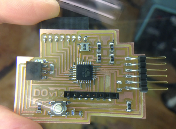
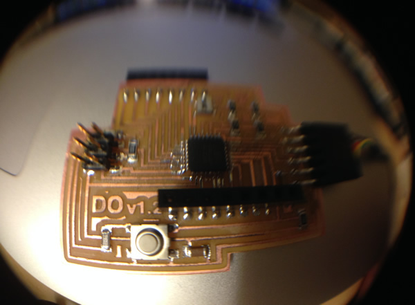
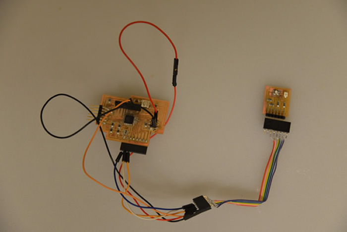
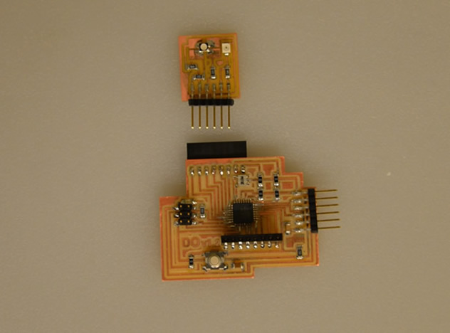
1- Central processing Unit: An arduino based board, with necessary memory to store the code to make the sensor(s) work, and with enough pins to control all the fingers or boards connected (for the final project i only implemented color sensor, but the project contemplates at least 3 more inputs).
2- The Case: for the main circuit: a 3d printed design that contains the main arduino board (designed and programmed on week 12).
3- The Belt: that holds all the componets in the hand. Casted in a Machineable wax mold with OOMOO.
4- Thimble: 3D Printed in PLA to hold the sensors in the fingertips.
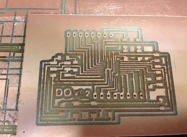
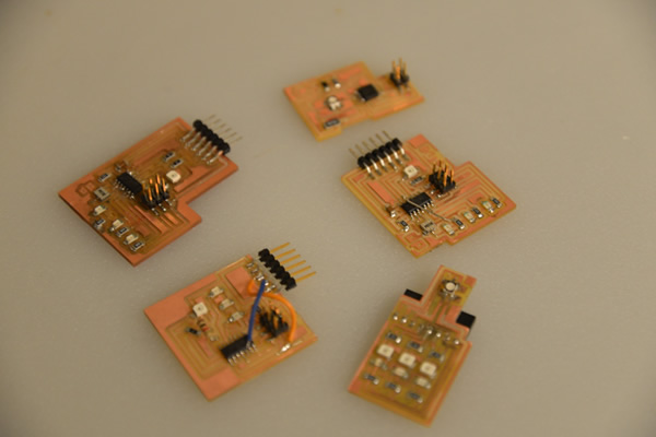
5- Sensor(s): Designed on EAGLECAD and fabricated using the Roland Modela MDX20 the design allows the use of many sensors including , color , pressure, temperature, proximity, etc. For the final project i only implemented color.
Here's a video of the Color Sensor working with a basic application programmed in Java.
htmaa_week13 from DIGIFAB on Vimeo.
Schematic Drawing of the final design explaining the different components.

2- Fabrication
The board-
Most of this was explained in the previous week , but i'll post some images of the schematic of the board and sensor.
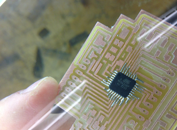
DO-Duino (hello arduino modified board).
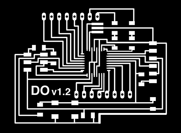

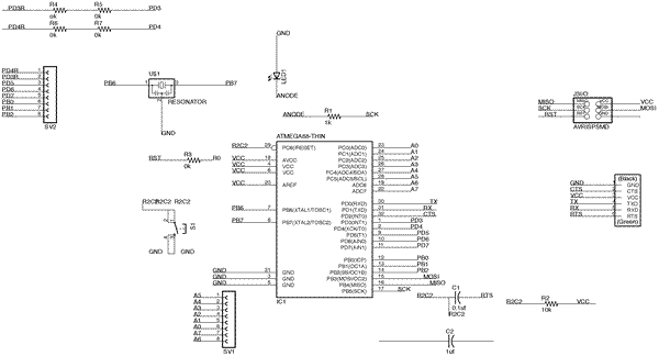
It was very important to study the pins and datasheet of the ATMEGA 328 to understand how to modiby and reorder the pins. Soldering all the parts was also a challenge but i think i am a master in the art of fabricating circuits!.
Sensor
Basically is a circuit with an RGB light and a photoresistor. The way it works is really simple , and after a lot of research , avoiding going for instructables or buying one sensor (a real one), i manage to design and create my own color sensor (after 13 versions!).

Because we have a sensor that can "see" many colors (photoresistor), what we do is: Assuming that you want to tell the difference from a green apple v/s a red apple, you can start by saying that red apple will reflect red light and absorb green light, and viceversa. So, if you shine a red light on both, the red apple will reflect much more light that the green apple, the brightest color is red!, conversely, if you shine green the brightest color will be green!, super simple.
Now, because this is a different type of color sensor , is relly sensitive to lighting conditions or distance to the color, usually is 3 - 5 mm depending on the type of photoresistor (check always the datasheet!).
now the basic algorithm for this sensor to work is this:
Place the sensor over white color
Do for about 3 seconds ()
turn on green LED
wait 50ms
record sensor reading G
turn off green LED
turn on red LED
wait 50ms
record sensor reading R
turn off red LED
turn on blue LED
wait 50ms
record sensor reading B
turn off blue LED
Place the sensor over Black color
Do for about 3 seconds ()
turn on green LED
wait 50ms
record sensor reading G
turn off green LED
turn on red LED
wait 50ms
record sensor reading R
turn off red LED
turn on blue LED
wait 50ms
record sensor reading B
turn off blue LED
with these values you can have a max white and max black readings and can apply a formula (similarity matching ) to normalize the readings of any color.
abs(new_reading - calibrating_reading)/calibrated_reading * 100 = similarity
in the code you just have to set the correct mapping formulas to maintain the colors between 0 and 255.
- Case and FingerTips:
To Print the plastic parts i used WHITE PLA (US$ 33 per KG on amazon) using a MAKERBOT 2, the resolution of the machine was good enough to produce first prototypes. To prepare the files i use the MAKERWARE software from makerbot.
The setting sfor the parts were: LAYER RESOLUTION: 0.15 mm , RAFT: ON , SUPPORT: ON, SHELLS: 3.


first prototipe,a two part system.... didn't work. The new design worked better because was a single part, i just had to remove the supports.


- The Belt:
First i designed the mold to milli it with the ShopBot Machine (many thanks to my friend Victor for the help! with CATIA). The ToolPaths were processed in CATIA with the machining module. very straightforward process and the shop bot translated the GCode from CATIA with no problems.


Casting the mold was easy. i used OOMOO following the same protocols that i followed on week 6. This was a two part process, first i had to put the magnets in the mold (strong ones!) and then put the OMMO very slowly so the magnets don't move (because of its strength, at a slight movement they just jump to the other side to stick to the other magnet!, so anoying!!!!).


After the OOMOO was cured, i flipped the casted piece and poor some OOMOO again to seal the magnets into the belt.


Because i had my circuits Ready since last week (i knew that this last week the shop will be full of people working so i wanted to avoid the problems with modela busy all the time). , it was time to start putting everything together.
- Assembly , tests and final programming.
To assemble the pieces was not easy at all, at the end i casted 3 belts, printed 3 cases and many fingertipsmodifying tolerances , ergonomics, etc. many models broke in the process.


Final prototype fully assembled!. now it was the time to test it.


Plugging the Device, it works!, it sends data to my laptop. Ready for final tests!


Interface programming.
I programmed a simple application in Eclipse (Java), to use the LEAP Motion Sensor with the final project. The sensor in my left hand gets the color from physical objects while my right hand draws on the screen changing thickness and erasing lines with gesture recognition.
here some pictures and a final video of DRAW IT! working perfectly.
HTMAA_ final project from DIGIFAB on Vimeo.