My final project is a blitz chess board that 1) automates the switching of the clock based on a piece being placed on the board and 2) could be extended to automatically annotate games. It consists of the physical integration of my output devices, input devices and serial connections projects.
To rehash what has been done so far. I first built an Arduino based chess clock with two LCDs that operated on a basic switching mechanism: push a button, flip the clock. I then constructed another Arduino system around a multiplexed switching system that could read the state of 64 different switches in a single loop. The details of these two implementations are contained in the input and output device pages. Finally, I got a serial connection up and running and wrote the code that could be used to parse the data stream into a state matrix of the board.
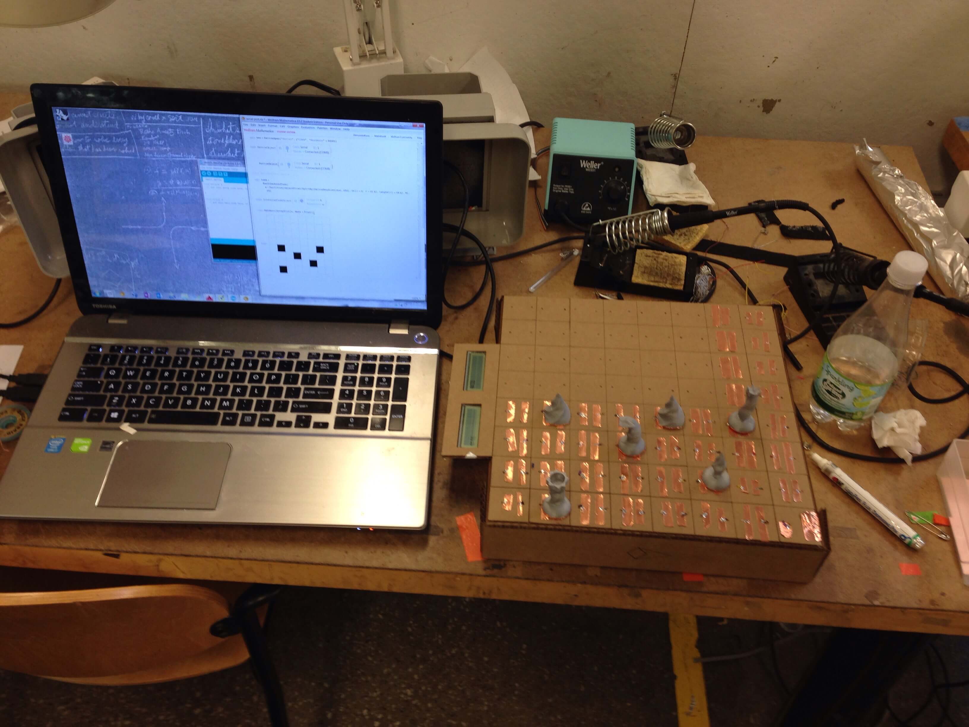
This week I integrated the electronics, built some example pieces and the board. We'll take each of these activities in that order.
So we have two subsystems to integrate: the board state tracker and the LCD setup. In reality, there only needs to be one signal that passes between the two boards: 1 (player 1 is playing) or 0 (player 2 is playing). In reality, because the code for the LCD system was developed for two different switches being used (a traditional blitz chess setup), I would have had to modify the LCD Arduino code to make it work. I played around with that for about an hour, but was unable to figure out how to do it without rewriting the main loop. Abandoning that, I was left to work with the sketch I developed for the state tracker. After a few failed attempts incorporating a delay, I discovered that I could essentially hold a switch closed for the LCD Arduino without affecting the loop (i.e. the code didn't depend on a pulse to ground, rather I could bring the lead to ground and leave it there until I was ready to switch). That made things relatively easy and I wrote that implementation into the final sketch.
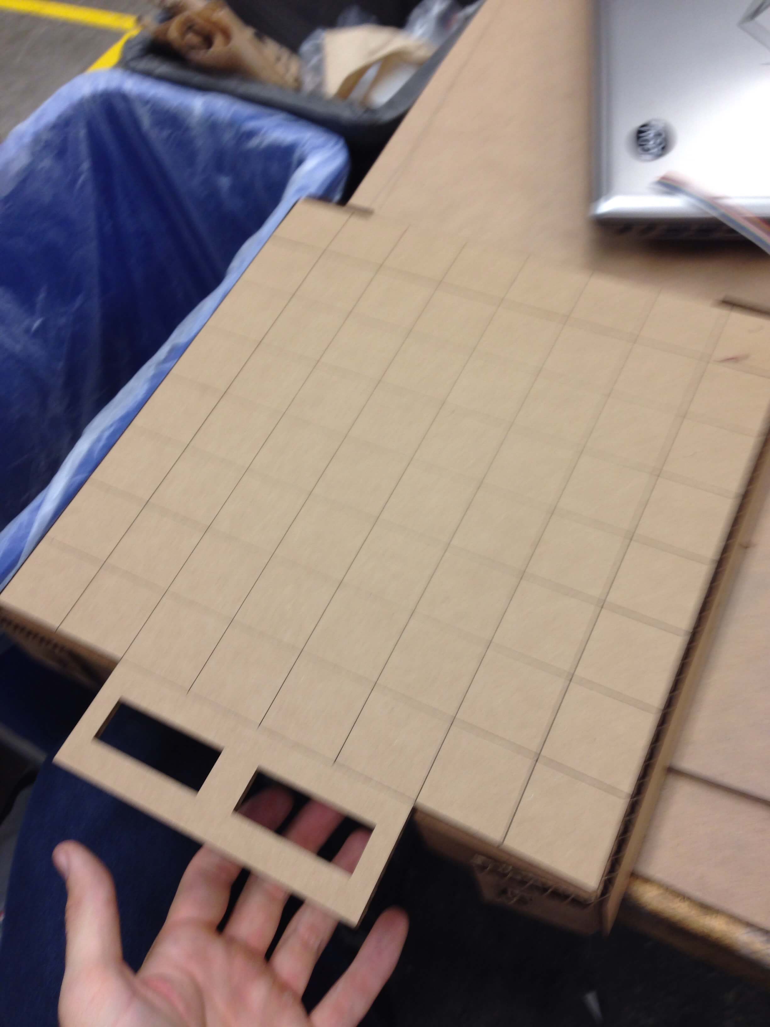
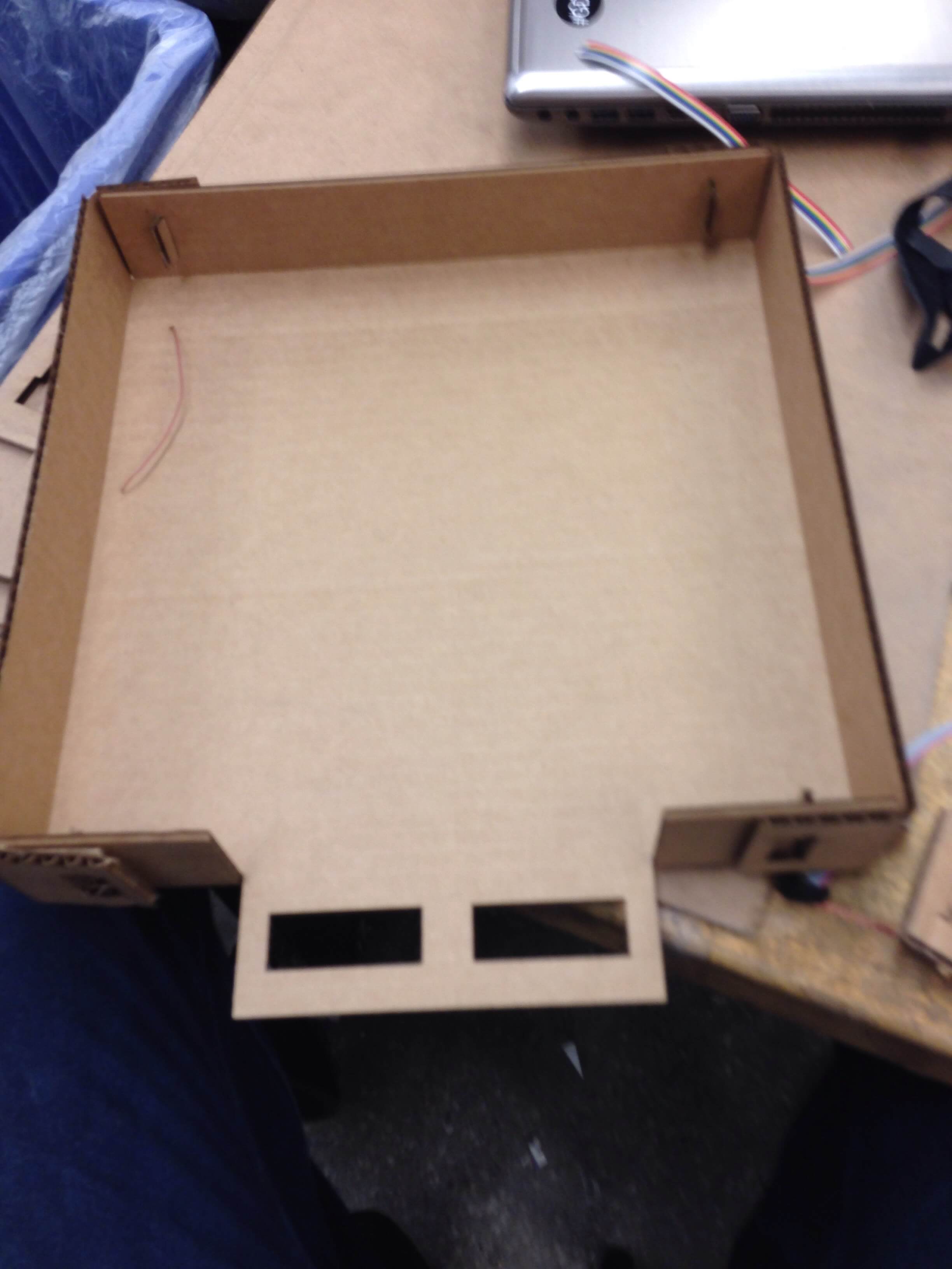
I decided to laser cut the board. I messed around with Rhino a bit to see if I could make a parametric model, but decided I just didn't have the time to learn a whole new software package. So I returned to my roots and fired up Autocad. To make sure that I got the press fit joints correct, I did a test cut and then finalize my model. I rapidly iterated through some different constructions but settled on this:
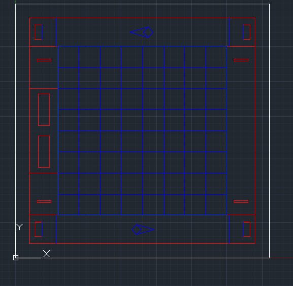
The board cut nicely, but I would have liked it to be a bit stiffer. Gotta use thicker board next time.
Taking inspiration from the Queen that I made during project 3, I decided to continue the theme of regular polygons rotated through space. I still think the queen is the most compelling piece, but these were good first iterations. I would definitely refine them if I was going into production. I drew everything in Antimony. The base was a common torus, the central axis was a (different) regular polygon rotated through space and the tops were all done in different ways.
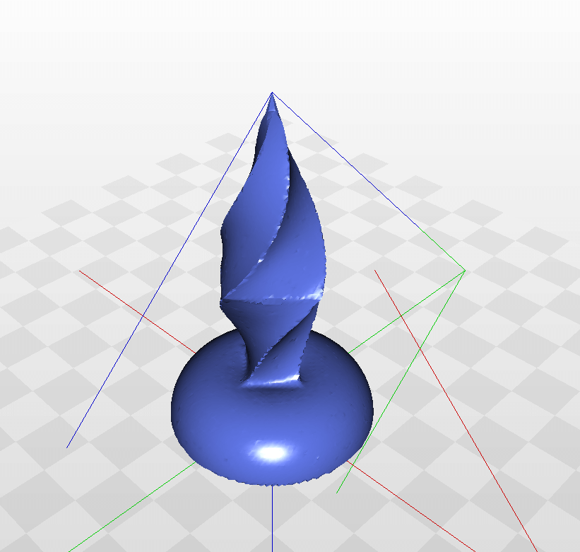
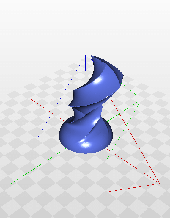
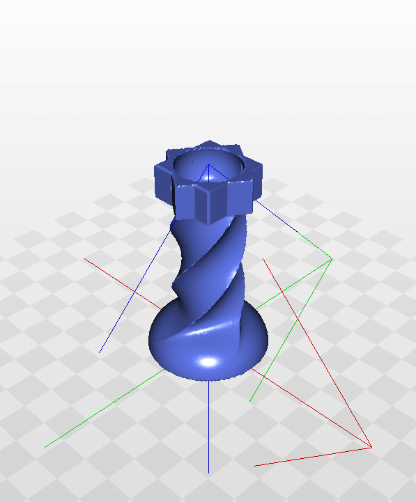
Queen King Pawn Bishop Knight Rook
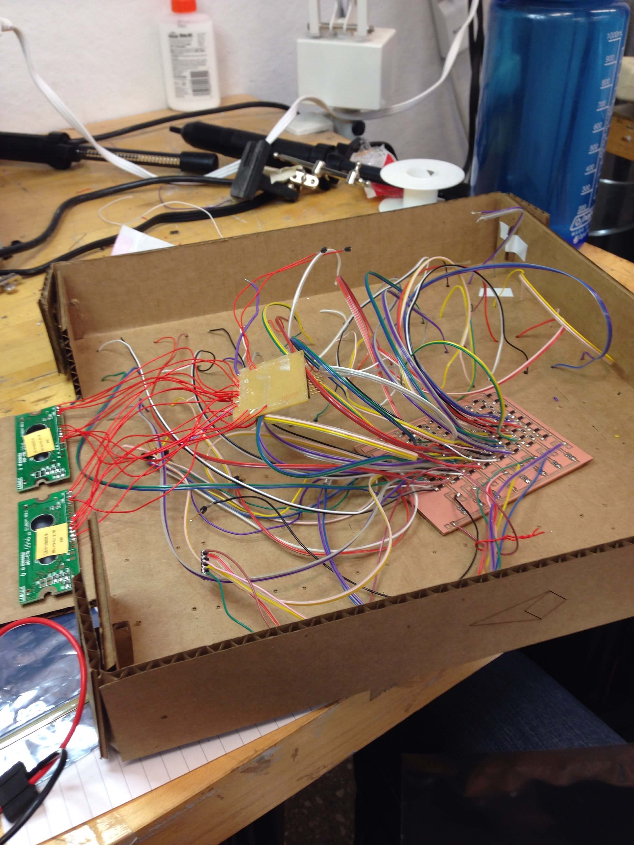
Most of this was the grunt work of hooking up wires and putting copper pads on the board and bottom of pieces. A lot of solder, wire and copper, but nothing too exciting.
And it worked. I cant describe the feeling of accomplishment.