FINAL PROJECT
Marble Madness
December 7, 2015
Outline
- Introduction
- Background
- Design
- Plain Wooden Building and Marble Run Blocks
- ISP Programming Header Board
- Capacitive Touch Sensor with LED Output Block
- Bluetooth Enabled "Listening" Block
- Marble Lift
- Materials
- Process
- Plain Wooden Building and Marble Run Blocks
- ISP Programming Header Board
- Capacitive Touch Sensor with LED Output Block
- Bluetooth Enabled "Listening" Block
- Marble Lift
- Assembly!
- Evaluation, Testing & Reflections
- Design Files & Code
Introduction
After spending far too long agonizing over what to make for my final project, I landed on the idea of making a dynamic, interactive marble run. I spent many formative years building extravagent marble runs using simple wooden blocks, and thought this would be a nice way to circle back to that experience. Here are the guiding criteria I considered while coming up with this project:
- Dynamic, with the potential for "long-term" or extended interaction
- Significant electronics component
- Melding physical shape or form with electronics-enhanced functionality
- Modular, with the ability to scope appropriately

My idea is to build a set of wooden marble run blocks, like the ones I grew up with, that are embedded with electronics that extend and enhance their functionality. These "enhanced blocks" will be self-contained; that is, they will each have onboard sensors, actuators, and batteries that allow them to be placed anywhere in the marble run construction. The "proof of concept" idea for the "enhanced block" is a block with a simple "marble detector" and LED output. This block will detect when a marble enters the block channel (using a capacitive touch sensor) and then light up an LED display.
Two elements I really want to incorporate into my marble-run system are: first, a marble "lift" that can bring marbles from the bottom of the marble run to the top. With this system, the whole marble run system becomes a physical "while loop", running "code" on physical bits, and taking input from sensors in the real world. The second element I want to incorporate is a simple programming interface that will interface with one or more of the sensors. This interface will allow users to change the parameters of the system and make simple changes to the embedded code running on each "enhanced" block.
Background
I took inspiration from the following projects:
- Wooden marble run building blocks: These beautiful wooden blocks provided inspiration for the basic physical form of my marble run blocks.
- Little Bits: This innovative toy company (founded by Media Lab and HTMAA alum Ayah Bdeir) produces modular, magnetic circuit components that can be assembled into playful, useful gadgets or toys. I love this company and product; I wanted to build upon their idea by more tightly coupling physical form and function.
- Cuboino: After coming up with my idea, I was referred to this thesis project by Media Lab alum Felix Heibeck. His project also includes actuated blocks for a marble run; I hope to build upon these ideas by having a continuously running system and a more interactive programming interface.
It turns out there are tons of marble runs, rollercoasters, and kinetic art pieces out there...but this may be the first that uses Bluetooth!
Design
This project is composed of a number of modular elements that I designed separately. Here I discuss the design considerations that went into each part of the system. Each component links to its corresponding section in the Process Section.
Plain Wooden Building and Marble Run Blocks
I started my design with the completely analog elements. I will need some simple building blocks that can support other blocks to give the system height. I will also want to have a number of analog blocks that can interface with the electronically-enhanced blocks.
For the building blocks, I decided to make a bunch of 1.5" x 3.5" x 3.5" and 1.5" x 1.5" x 3.5" pieces. These will be easy to stack on top of each other in different configurations. I can cut up my 1.5" x 3.5" x 96" beams using the chop saw to get these pieces.
I wanted to make pieces that could slow down the marbles, since this was an issue mentioned several times in the Woodgears marble run page. These will include a 3.5" x 3.5" corner block (originally planned to have this be 2.5" x 2.5"), a 3.5" x 3.5" circle block, and channel blocks with waves, zigzags and corner exits that will slow down the marbles. I will also make some straight channel blocks for testing. The channel blocks will all be 2.5" wide and 6" long.
The marbles are about 5/8" wide, so I plan to make all channels/ holes 7/8" wide to accomodate the marbles. I want the tracks to slope downward to ensure that the marbles move; I will have the depth of the channels vary from 1/2" deep to 1" deep over the course of the channel. The corner block and circle block can also vary between these depths.
To fabricate these pieces, I will design STL files in Rhino, and use PartWorks3D to make cuts using the ShopBot. I will then cut the beam into segments using a bandsaw. I will need to leave a little room on each beam for fixturing. Here is a sketch of these different block typologies:

I did my modeling in Rhino. Some of the shapes took a little bit of creative thinking, but I'm pleased with the results. I needed to do 3D modeling so that the channels could be sloped. Here's an image of the models, and the curvy block after using the "Make2D" command. I laid the blocks out end-to-end so that they would fit on my material. You can find Rhino design files in the Design Files & Code section.


ISP Programming Header Board
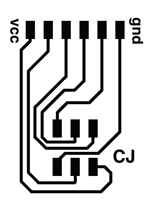
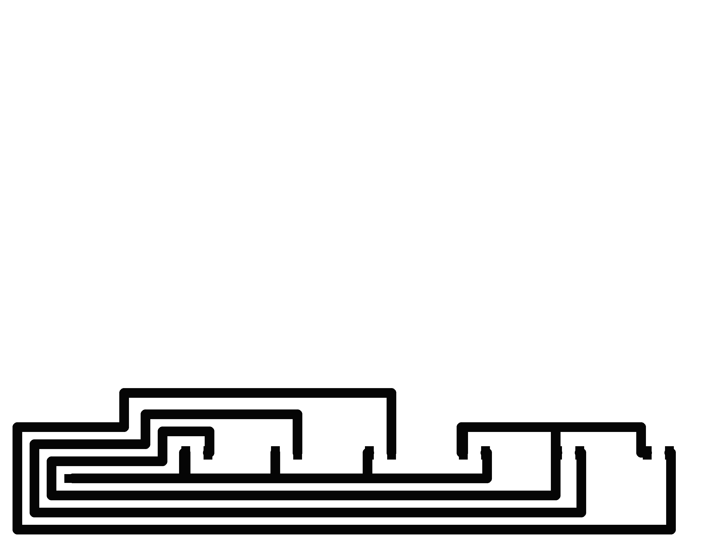
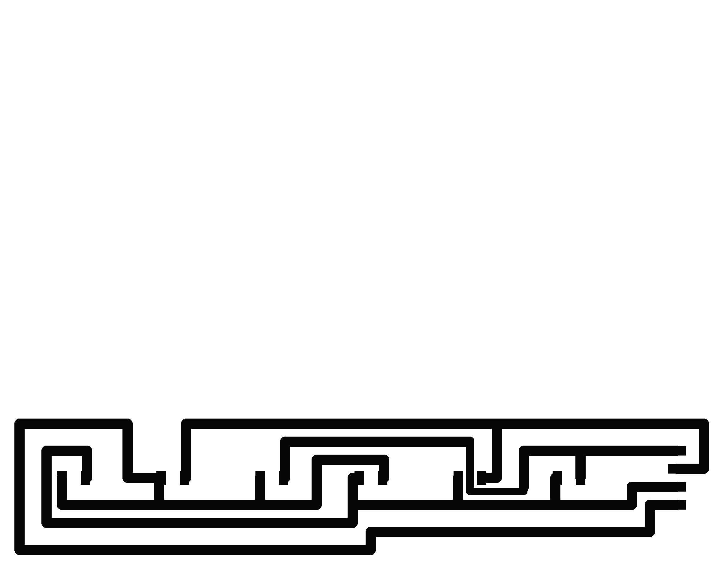
Another relatively easy design element. Instead of soldering an ISP header onto every board, I wanted to make a header board that breaks out the ISP pins and can be "held" against the board I am programming. Here are the traces and board outline. I used a .032" width wire for the dimension of the board outline, and designed it specifically to mirror a convenient layout for ISP pins on a typical board.
From L to R, the breakout pins are: VCC, MOSI, MISO, SCK, RST, GND.


Capacitive Touch Sensor with LED Output Block
I had originally planned to use a sonar sensor to detect when the marble entered a particular channel block, but after testing my Input Device from Week 9 with a marble, I learned that the sonar sensor was not effective at detecting a marble. This makes sense, because the marble is pretty small, and it is not a good reflective surface.
Instead, I decided to use a capacitive touch sensor to detect the marble. I again tested my Input Device from Week 9 with a marble, finding that the capacitive touch sensor could indeed detect the marble (even though the effect is quite small). I will have a single capacitive touch sensor that lines the channel of the marble block. I will then plan to Charlieplex 12 LEDs (running off 4 pins, because N(N-1) = 4(3) = 12) which light up when the marble is detected. I want to design the circuit board to fit on the profile of the marble run block, which is a 2.5" x 1.5" face, with a 1/2" deep and 7/8" wide slot cut out of the top. The traces for the LEDs will be made from copper foil and will run the length of the 1.5" x 6" block. The capacitive touch sensor will also be made from copper foil and will run down the channel. I plan to make the LED traces thicker so that they are easier to cut from foil.
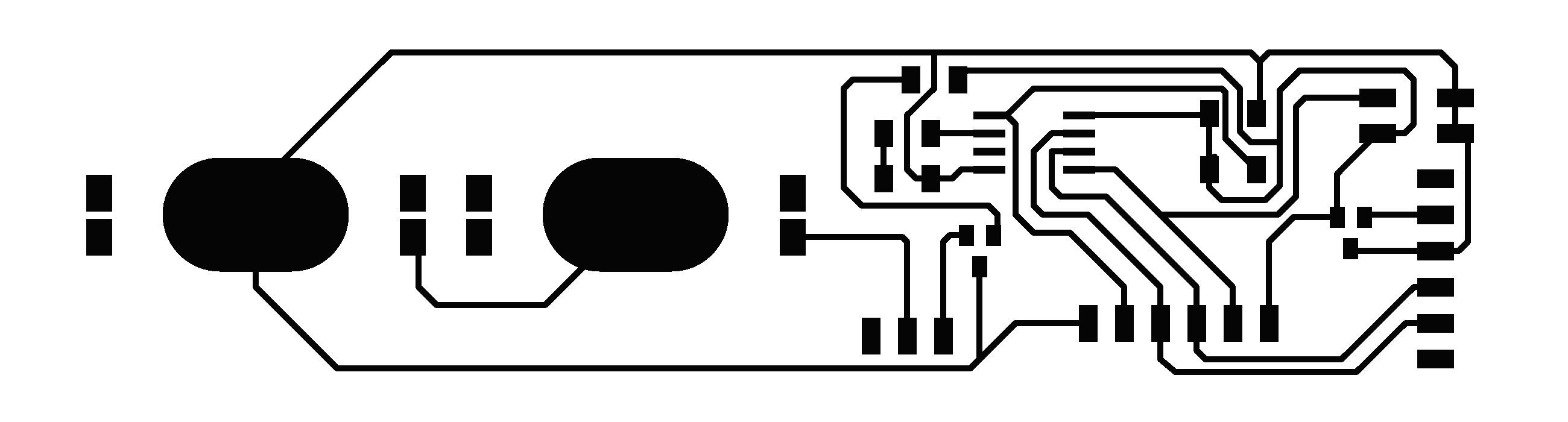
Here are the traces and board outline for the main board of the capacitive touch sensor board, as well as an image of the board in Eagle (minus a bit of post-processing). I've broken out the pins that will go to the LEDs on the sides of the block, and break out the capacitive touch pin. I'll use a jumper wire to attach to that pin. I also plan to use some of the epoxy film underneath the ISP breakout pins to make sure they are isolated for the proper pin. The traces definitely get a little tight in some places, but I checked the png in fabmodules and it looks like everything should be milled properly.


Here are the traces for the LED arrays on the sides of the channel blocks. I used a trace width of 0.056" for most of the traces (except in one part where there was a squeeze). Hopefully these will be easier to cut on the vinyl cutter.


Bluetooth Enabled "Listening" Block
Next up, designing a board that uses Bluetooth communication to wirelessly connect to the user's phone or laptop. The output device on this board will be a small servo motor that controls the flow of marbles (probably using the servo to alternately block or unblock a channel). I would like the user to be able to program functionality that is communicated over Bluetooth to the block and can trigger the release of the marble when a user-defined event (such as receiving an email) happens.
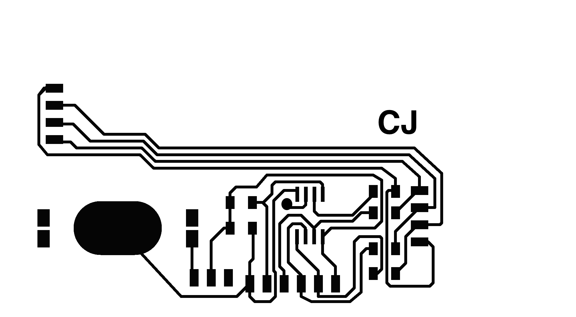
One necessary consideration for this board is general layout: I need the servo to be in a specific location. I think I will design the board to fit within the 1.5" x 6" face of the side of the marble block. I will cut a notch in the top of the block that will hold the servo. Another consideration is power. The HM-10 module needs a supply voltage of 2.0 to 3.7 volts, so the 3V coin cell battery I'm planning to use should be fine. Servos are a little trickier, because they need to run on 5V. After asking around (thanks JF and Eric!), I decided to try putting two 3V coin cells in series to get 6V, and then regulating that voltage down to 5V for the servo, and 3.3V for the HM-10 module. Eric said the biggest consideration for this type of setup is to make sure there is enough power for each device. Since Bluetooth is such a lower-power process, I think I should be fine. We will see! I based my design off Neil's basic servo board and Jasmin's Bluetooth breakout board; here are the designs.


Marble Lift
I have next to no experience with mechanical design, which is what makes this component of this system so exciting and intimidating. I started with sketching out some ideas for the marble lift, drawing some ideas from this Instructable. I plan to have a nylon or fabric belt with nails or notches that grab the marbles. The belt will run on two spinning wheels, and will be supported by a track (much like the channel blocks) that the belt runs through. The track and the wheels will be supported a beam at the high end, and two blocks at the low end. Everything will rest on a base to keep the spacing constant.

I feel like I've been shying away from actually understanding how motors work. I actually don't think I need anything more complicated than a DC motor for this project, since I just need continuous rotation in one direction, and I don't need to set position. However, I still wanted to develop a better understanding of H-bridges and PWM for my own understanding.
PWM, or Pulse Width Modulation, refers to varying the amount of time a signal stays on during a clock cycle. The percentage of time the signal is on (the "duty cycle") corresponds to the "amount" of voltage a device sees. This allows you to vary voltage continuously between high and low. See this helpful Arduino tutorial for more info. There is an Arduino function for PWM, but in Neil's C code, it looks like he is literally just turning the signal high, delaying for the duration of the duty cycle, then turning the signal low. An H bridge is an electronic circuit that enables a voltage to be applied across a load in either direction. Without digging into the low-level electronics of the H-bridge too much, it looks like there are just two input pins on the H-bridge circuit. The direction of the motor depends on which one you set high (IN1 vs IN2 in the code below). Here's an illustrative snippet from Neil's code:
for (cycle = 0; cycle < cycle_count; ++cycle) {
   //
   // turn forward fast
   //
   clear(bridge_port, IN1);
   set(bridge_port, IN2);
   for (count = 0; count < PWM_count; ++count) {
      set(bridge_port, IN2);
      on_delay();
      clear(bridge_port, IN2);
      fast_off_delay();
      }
   //
   // turn reverse fast
   //
   clear(bridge_port, IN2);
   set(bridge_port, IN1);
   for (count = 0; count < PWM_count; ++count) {
      set(bridge_port, IN1);
      on_delay();
      clear(bridge_port, IN1);
      fast_off_delay();
      }
   }
I chatted with JF about stepper motors, and think I now have a clearer understanding of how they work. Basically, inside the motors there are a number of different coils of wire, and there are magnets in the shaft of the motor. When a coil of wire is energized, it produces a magnetic field (freshman physics coming back in a big way here...) and the magnets in the shaft shift to align with this field. In a unipolar stepper motor, coils of wire have a central power line; based on which side you choose to ground, you can energize one side of the coil and create a magnetic field that turns the shaft in a certain direction. When you energize the other side of the coil, you'll get a magnetic field with reverse polarity that will turn the shaft in the opposite direciton. In a bipolar motor, you energize the whole coil; in order to create both directions of magnetic field, you need to use an H-bridge so that you can run current across the coil in either direction. You can get very precise positioning using a stepper motor. This Adafruit tutorial and this Youtube video were both great stepper motor resources.

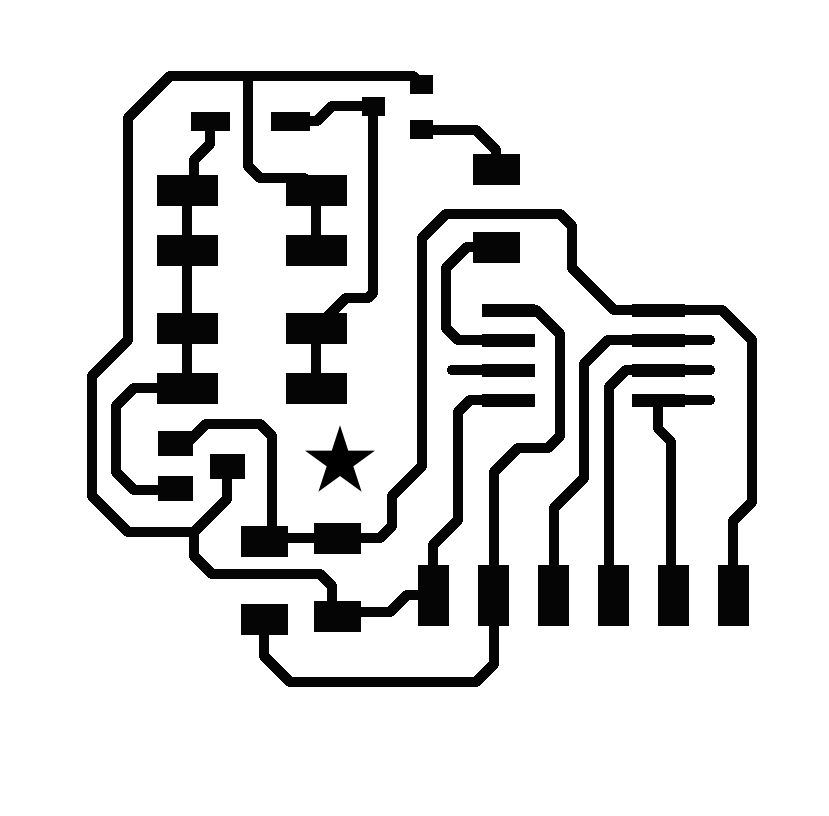
Now, back to my actual project. JF helped me with the design of my DC motor circuit board. I will power the board with an external power source, that is regulated to 3.3V for the ATTiny45. I use an NMOSFET to control the motor; basically, when the voltage on the gate pin of the MOSFET is set above a certain threshold (e.g., when the ATTiny45 sets this pin to "high"), the Vgs (voltage between the gate and source) will cross a certain threshold, and the drain and source will start conducting. This will connect the motor to ground, which will create a voltage drop across the motor. Here's my design:


Other Ideas for Enhanced Blocks
I originally came up with concepts for two other "Enhanced Blocks". These were to be: a block outfitted with a sound sensor, that would play a "jingle" on a speaker when it "heard" a marble; and a block that used a pyroelectric motion sensor to detect the marble, and then spun a flag on a servo when the marble passed by. I am excited by these ideas, but decided to cut them after class when Neil said: "Don't make this your life's work". I think the more innovative/ interesting parts of this project are the marble lift and the programming interface, and I want to spend more time developing those instead of making more Enhanced Blocks. These blocks can come during IAP, or when this project turns into a multi-million dollar Kickstarter campaign...
Materials
Exact component prices from the Fab Lab Inventory are recorded alongside estimates for scrap materials and "found" items. What is more interesting than the actual prices is noticing the distribution of expenses; batteries and specialty chips (like the HM-10) dominate the cost. The process of putting together this BOM also makes me appreciate having access to a shop like the CBA; I was able to gather many materials (e.g. scrap acrylic and cardboard) without having to pay full prices.
| Part | Part Number/ Details | Quantity | Vendor | Unit | Total |
|---|---|---|---|---|---|
| Marbles | 1 | Artisan & Craftman | $4.50 | $4.50 | |
| Wood | 1.5" x 3.5" x 96" beam | 2 | Home Depot | $3.00 | $6.00 |
| Wood | 1.5" x 2.5" x 96" beam | 1 | Home Depot | $1.50 | $1.50 |
| PCB Stock | 3" x 2" single-sided sheets | 2 | Global Laminates | $0.18 | $0.36 |
| PCB Stock | 6" x 4" single-sided sheets | 1 | Global Laminates | $0.32 | $0.32 |
| Copper foil | 3M #1126 | Budnick | $0.50 | $0.50 | |
| Assorted LEDs | 1206 SMD | 13 | Digi-Key | $0.13 | $1.69 |
| ATTiny45 | IC AVR MCU 4K 10MHZ 8SOIC | 3 | Digi-Key | $1.23 | $3.69 |
| Assorted resistors | 1206 SMD | 10 | Digi-Key | $0.01 | $0.10 |
| Slide switches | SPDT 12V 100MA GW | 2 | Digi-Key | $0.84 | $1.68 |
| Assorted capacitors | 445-1423-1-ND | 3 | Digi-Key | $0.07 | $0.21 |
| 3.3V 100mA Regulator | LM3480IM3-3.3/NOPBCT-ND | 1 | Digi-Key | $0.32 | $0.32 |
| 5V 1A Regulator | ZLDO1117G50DICT-ND | 1 | Digi-Key | $0.34 | $0.34 |
| 2x3, 2x2 pin headers | 649-95278-101A04LF | 3 | Mouser | $0.72 | $2.16 |
| Female FTDI header | ED23064-ND | 4 | Digi-Key | $0.48 | $1.92 |
| 3V Coin Cell battery | CR2025 | 3 | Sparkfun | $1.95 | $5.85 |
| 20mm coin cell battery clip | PRT-11892 | 3 | Sparkfun | $0.95 | $2.85 |
| Microservo | HKSCM9-5 | 1 | Hobby King | $2.99 | $2.99 |
| DC Motor with gearbox | 1 | Jameco (?) | $4.00 | $4.00 | |
| Bluetooth module | HM-10 | 1 | Amazon | $13.99 | $13.99 |
| 9V battery | 2 | Duracell | $4.50 | $9.00 | |
| PLA | 0.75kg Spool 2.85mm Filament | Ultimaker | $1.00 | $1.00 | |
| Scrap acrylic, scrap cardboard | $5.00 | $5.00 | |||
| Wood glue, super glue, paste, etc. | $2.00 | $2.00 | |||
| Nails, dowels, wire, etc | $1.00 | $1.00 | |||
| Fabric | $0.50 | $0.50 |
TOTAL COST: ~$75
Process
Plain Wooden Building and Marble Run Blocks
First up, using the Shopbot for CNC Milling. I used Partworks and Partworks3D to make toolpaths from the 3D and 2D patterns I designed in Rhino. I followed the procedure for 2D and 3D milling from Week 4 and Week 6, respectively. Based on Tom's suggestions, I used a a .25" endmill, with a 10k spindle speed, 90 ipm feed rate, and 40 ipm plunge rate. Everything worked well. One small issue I had was that the endmill wasn't quite long enough to go all the way through my wood. In the few places I needed to go all the way through the wood (I was mostly doing pocket and surface cuts), I needed to use a longer endmill. Many thanks to the lovely Kim Smith for being a great Shopbot buddy!
I spent quite a bit of time post-processing the blocks. This procedure consisted of chopping up the beams into blocks using the chop saw, and sanding them by hand, with the pneumatic orbital sander, and with the belt sander.


The channel blocks have a sloped surface, but the corner blocks don't. I decided to add "rounded corners" to the corner blocks to make it easier for the marble to roll through the block. I quickly designed corner pieces in Rhino, and printed them on the Ultimaker at "Normal Print" speed. These would have been a good candidate for molding and casting, but I didn't feel making a mold was the best use of my time, given my tight schedule. I used wood glue to attach them to the corner blocks.


ISP Programming Header Board
I used the SRM-20, following my instructions from Week 8. My first milling attempt (with a slightly outdated board design, see below) came out with a lot of burrs. On Matt Carney's sage advice, I swapped out the 1/64" endmill for a new one, and the board came out beautifully. I used 0.1 mm cut depth and 3 mm/s speed. There were a few merged traces that I will have to fix - I think I may be using the wrong design rules file? - but otherwise very happy with how the board came out. Stuffing just required adding the 2x3 ISP header.
Design considerations if I make this again: First off, I used less restrictive design rules so I got two merged traces. This could have been avoided if I'd been more aware of the problem. It would also be nice to have some sort or registration mark so that it's easier to match up this header with the pins on the board.


A few days later, after some experimentation with tape and a plastic clip, I found that this ISP header setup was not reliable enough for general use. I ended up soldering FTDI headers to each of my boards in place of the ISP header pads and soldering FTDI female headers to the breakout board. It's an extra step beyond the regular ISP header, but it works reliably!

Capacitive Touch Sensor with LED Output Block
I milled this board in the same SRM-20 session as the ISP header board and the BLE board. The first time I milled the board, the right half of the board didn't get milled all the way through. I increased the cut depth to 0.11 mm and got a much improved board. Again, though, I had merged traces which ended up being a bit of a pain to separate. More attention will be paid to design rules if I redesign! I stuffed the board with 499 ohm resistors for the LED array, a slide switch, the standard 10k ohm resistor and 1 uF capacitor, an ATTiny45, and the coin cell battery clip. The LED pads on the side of the board will be attached to the copper foil LED traces that will be placed on the edge of the channel block.


I spent quite a lot of time trying to use the vinyl cutter for my copper traces. These traces will go on the side on the channel blocks. At first, the blade I was using was too dull, so John helped me replace it. Then, I experimented with a variety of different speeds and forces. With the new blade, I had success with 50g of force and 1 cm/s speed. Even with these settings, I had to be extremely careful and meticulous while weeding my traces so that they wouldn't get pulled up. Copper is a much more difficult material than the vinyl, but I'm glad I got to finally experiment with this skill. Making thicker (0.056") traces in Eagle definitely helped; I don't think this would have worked as well with thinner traces.


I carefully transfered the copper traces to the sides of one of the channel blocks, and soldered LEDs onto the traces according to my Eagle design. I then used a glue gun to attach the board to the front of the block, and soldered tiny wires to connect them. I first tried out the simple Charlieplexing code that I had used in Week 8. It worked beautifully!


After seeing that my board seemed to be stuffed and assembled correctly, I set about trying to program functionality into the capacitive touch sensor. This proved to be more difficult than anticipated. I did not include a serial interface on this board, so I didn't have a good way of monitoring the step response coming from the touch sensor. In an attempt to gain insight into what was happening on the board, I used the LED array as a debugging tool. That is, I flashed different LEDs depending on the step response, as seen below. I tried to use this method to narrow down the band of values that the step response was producing. To measure the step response, I used Neil's capacitive touch sensor code as well as some routines from Matt Blackshaw.
 if (value < 170) {
    flash(C,A,delay);
  } else if (value >= 170 && value < 340) {
    flash(C,B,delay);
  } else if (value >= 340 && value < 510) {
    flash(C,D,delay);
  } else if (value >= 510 && value < 680) {
    flash(D,A,delay);
  } else if (value >= 680 && value < 850) {
    flash(D,B,delay);
  } else if (value >= 850) {
    flash(D,C,delay);
  } else {
    flash (A,B,delay);
  }
Unfortunately, I was unable to see a change in the step response - i.e., a change in the LED - when my hand (or a marble, for that matter) came near the sensor, so I decided to leave the LED array program on the board and save the interesting signal processing work for another time.
Update 12/16/15: Based on Neil's feedback from the final project presentation, I now realize that this sensor will not be able to sense anything because the marble passing over the sensor isn't grounded. If I go back to this block, I will want to put two cap touch sensors on the sides of the blocks; the marble will change the capacitance between them.
Bluetooth Enabled "Listening" Block
I milled this board in the same session as the ISP header board. It also came out beautifully, and also has a few merged traces that I will fix with an exacto knife. There are also a few tiny traces left between the legs of the ATTiny45 - I should use more offsets next time, but I can pull these off with tweezers for now.

After stuffing the board, I have a few design considerations for a potential v2 of this board: first, the merged traces were more of a pain that I would have liked. I would definitely fix those next time. Second, it would have been good to have more surface for the female FTDI header. It's hanging off the edge a little which isn't very structurally sound. Third, I would make longer pads for the ATTiny45 legs; it was a little tricky to get it on there.
This board uses the standard 10k ohm resistor and 1 uF capacitor, as well as a 5V regulator, 3.3V regulator, 1k ohm resistor with LED, and two coin cell battery clips. The Bluetooth HM-10 module is connected using the FTDI female header.

One of my first major challenges came in the form of programming and debugging this board. I had everything hooked up correctly and was able to program the board using the avr-gcc toolchain, but the servo behavior was not as expected. Jonathan helped me troubleshoot my code, and better understand the principles of servo operation. This Sparkfun tutorial was also a good resource for learning about servos. Here's the gist of the tutorial:
Frequency/period are specific to controlling a specific servo. A typical servo motor expects to be updated every 20 ms with a pulse between 1 ms and 2 ms, or in other words, between a 5 and 10% duty cycle on a 50 Hz waveform. With a 1.5 ms pulse, the servo motor will be at the natural 90 degree position. With a 1 ms pulse, the servo will be at the 0 degree position, and with a 2 ms pulse, the servo will be at 180 degrees. You can obtain the full range of motion by updating the servo with an value in between.
Even armed with this knowledge, and running a modified version of Neil's servo code, things still weren't working. The servo behavior was very erratic; it would turn, but then wouldn't do anything for 30 seconds or so, even though it was supposed to be turning continually. Amanda helped me use the oscilloscope to debug my board. The signal on the control pin looked great when the servo was connected, but was erratic when the board was connected to the servo. We found that there wasn't enough power to run the servo and power the board; when the servo drew power, it was taking power away from the board and reseting it. Amanda suggested that the problem was that I was using the 100 mA regulator instead of the 1 A regulator. After swapping out the regulator (with a bit of a hacky wire), everything seemed to work well.


Next, I combined this servo code with Neil's hello.ftdi.44.echo.c program and a simple Tkinter interface to create a program where you can control the movement of the servo from a button on your computer (through a serial connection). This is the first step towards controlling the servo via Bluetooth.
After controlling the motor via serial, it seemed like it should have been a small step to controlling the motor via Bluetooth. Indeed, the switch from serial to Bluetooth was quite easy. I just removed the Tx and Rx serial pins and plugged the HM-10 Bluetooth module into my board. I was able to communicate with the board through Bluetooth using the "LightBlue" terminal application on my laptop, which lets you send and receieve communications over Bluetooth. Here is a video of me controlling the servo from the "LightBlue" application, and then controlling the flow of a marble with the servo mounted on a channel block.
However, in the course of further testing and usage with Bluetooth, I uncovered some unreliable behavior in my servo that I suspect is a timing and/ or power issue. The servo will seemingly operate normally for some time (e.g. for about 4 input cycles), but then it will not complete the full turn of the servo, or it will turn several times, or not at all. I have spent quite a bit of time trying to debug this issue, but have not quite found the solution. One suspicion that came out of a debugging session with Eric (thanks, Eric!), was that the timing of the processor was somehow off by a multiplier, because the pulse width sent to my servo looked like ~3 ms instead of ~1 ms. It's also quite possible this is a power issue; e.g., if the load of the servo is too much of a drain on the processor, it could make the processor "brown out" or temporarily lose control.
Because this behavior was only moderately unpredictable, and the Bluetooth control does sometimes work, and this block is ultimately not essential to the operation of the marble run, I decided to press on and work on other issues. I did, however, download the LightBlue iPhone application, which, similar to the desktop application, lets you send characters to a Bluetooth device. Though this was not exactly the user-friendly and multi-faceted programming interface I had dreamed of, it does get the job done.
Marble Lift
The production process for the marble lift was a little more haphazard than other components, because it involved so many steps, and because I was the least sure of how all the parts would fit together. I first designed, milled and stuffed my motor control board. I milled it on the SRM-20, which, at the time, was not producing quite as beautifully as earlier in the week. After some aggressive deburring, though, I was able to produce a usable board.
Next, I produced the main wheel for the marble belt. I milled a 1" thick, 3" diameter foam wheel on the Desktop Shopbot. To do so, I first milled a wide, circular pocket cut to get the foam to the correct thickness, then a quick profile cut to get the correct diameter. I used a .25" endmill, with 6000 spindle speed, 150 ipm feed rate, and 50 ipm plunge rate (based on Sam's suggestion). The foam cut quite easily and make a nice wheel. Afterwards, I covered the face of the wheel with artist's tape and strips of "sandpaper" tape to grip the belt.
After foam milling, I used the laser cutter to cut acrylic wheels that would sit on either side of the foam wheel and act as guides for the belt. One of the acrylic wheels will also connect to the motor shaft. I tested several different shapes and sizes of cutout in order to get a wheel that would fit snugly on the motor shaft. I used .125" thick white acrylic and did my cuts on the Spirit laser with 100% power and 1% speed.


To program the motor, I wrote an adaption of Neil's DC motor code (without the H-bridge). I could not find a datasheet for the motor, but it seems to run on as little as 5V. I again used the oscilloscope to make sure I was sending the correct signals to the motor. The motor runs even without sending it a PWM signal, but I sent different PWM signals, and visually verified that they resulted in different motor behavior. For this project, I will just run the motor at one speed, but I could imagine wanting to have the ability to control the motor speed more precisely at some point. This video shows oscilloscope output of slow then fast PWM signals to the DC motor.
I combined my acrylic wheel and the motor for one of my first moving parts...a rotating wheel! Yay!
Next, I needed to produce the actual conveyor belt. I used fabric donated by my lovely roommate Shirlee, and cut a 1" strip on the Spirit laser with 7% speed and 40% power (I tested a few settings first before finding something that worked). Then, I used the Spirit again to cut cardboard "hooks" that would support the marbles as they were drawn up the conveyor belt. I cut out the cardboard pieces using 100% power and 1% speed; I made raster folding marks with 50% power and 5% speed. Finally, I glued the cardboard "hooks" onto the fabric strip using fabric paste.


Next, I set about assembling the actual marble lift. This, as you might have expected, took much longer than expected. In retrospect, I wish I had modeled this assembly more carefully so that I could have added registration marks and construction guides during production. As it was, things came together well enough, though the construction feels a little haphazard and it definitely has a hand-built look. I used a combination of screws, wood glue, dowels, super glue, and a glue gun to construct the marble lift and attach it to the base. I also used thread to sew the belt into a loop. It's a bit rickety, but it works!


After putting together the lift, I noticed that marble could only enter conveyor belt above the wheel, or else it would get thrown off the belt. This meant that the total vertical height of the marble lift was pretty small. To address this problem, I quickly designed and pulled together a "cage" to fit around the wheel so that marbles could enter the wheel closer towards the bottom. To do so, I tested several different designs, which I cut out of .25" scrap acrylic on the Spirit GCC laser (100% power, .7% speed, 2 passes, 550 DPI - as opposed to usual 400 DPI). After finding a profile that worked, I glued three pieces of the acrylic together to make a relatively effective - and colorful! - cage to support the wheel.
I also cut a number of "half" step wooden blocks (.75" thick) that allow subsequent channel blocks to be placed closer together in height (instead of a whole 1.5" apart).


Assembly!
Assembly was, again, a bit more haphazard than I would have liked. I didn't give a ton of thought to how I would attach my electronics to the wooden pieces, and ended up just using a glue gun and tape to put everything together. I do think the exposed copper traces look very nice, and there is a certain appeal to the exposed electronics. In the most practical sense, they make it easier to debug, troubleshoot, and modify the electronics. In an ideal scenario, though, I think I would have tried to hide more of the wiring and batteries within the blocks, even if some of the core functionality of the boards were exposed.


I "assembled" the marble run for a first pass. It's not perfect by any means, but it works! Due to the height of the marble lift, there unfortunately isn't much room for creative routing. However, you can arrange any number of blocks within the loop of channel blocks. I had to carefully arrange the blocks to make sure that the heights of the channel blocks matched up so that marbles would actually flow between them without getting stuck or rolling off the tracks. All the extra blocks I produced came in handy for generating the height needed for all the blocks in use. Once I got a perfect configuration, it was tempting to bolt or glue the blocks together; however, I think keeping the blocks separate is more in keeping with the spirit of this "toy". After all, routing blocks in a viable way is one of the interesting parts of the game. Here are some videos of the marble run in operation, including a close-up of the Bluetooth-controlled servo (each movement of the servo is triggered by me sending a command through LightBlue).
Based on my observations during this first run-through, I decided to work on a few finishing touches to make this look less like a kindergarten art project (!) and to make the marbles run through the track more smoothly. I first laser-cut a small "flag" for the servo motor, instead of the cardboard I'd taped on earlier. I used .125" scrap acrylic on the Spirit GCC laser with the same settings as before (1% speed, 100% power). I used a glue gun to attach it to the servo arm. I also sanded the entrances and exits of several channel blocks in hopes that this would allow the marbles to enter and exit the blocks more smoothly, and not get caught on the edges. I also cleaned up the tape attachments on the Bluetooth-servo block.
Evaluation, Testing & Reflections
This project was an investigation of building an electronically-enhanced and enabled marble run block kit. It ended up involving a surprising number of complex details at many scales and required the use of many skill sets. I was happy that I was able to draw upon skill sets I built earlier this year (e.g. laser-cutting and 3D-printing) for quick additions to my design. Through the course of the project, I encountered several different avenues that offered much more to explore, both technically and conceptually.
From a testing and evaluation perspective: the basic functionality of the marble set was self-evident: would a marble be able to travel through the channels, roll onto the conveyor belt, and be carried up to the top of the run? In many cases and configurations, yes! I was able to come up with several configurations in which the marbles would travel the entire cycle continuously; the marble lift, especially with the addition of the acrylic "cage", turned out to be quite robust. That said, one of the biggest difficulties with the blocks themselves was aligning the channels and making sure the marble wouldn't get caught on the edges. I probably should have tested block designs before producing them, but since I wanted to batch my milling work (Shopbot setup involves a lot of overhead), I designed something I thought would work and went ahead with milling it before testing. Additionally, a v2 version of this project should involve registration marks or even magnets for aligning blocks and holding them together. Overall, I think I should have thought more carefully (and designed more precisely) how the different wooden components would fit and stay together.
In terms of electronics, I used several standard tips and tricks to test my boards as I produced them. That is, I made copious use of the multimeter while stuffing (to make sure I didn't short anything), and used serial output and an oscilloscope to debug output from my boards once they were running code. I was successful in producing three boards (plus the ISP breakout header) that were all able to be programmed. Another evaluation metric is how well they did what I wanted them to do. In that sense, the motor board worked perfectly; the capacitive touch board worked partially, and the Bluetooth board worked intermittantly. I was not able to get the capacitive touch sensor working, but I was able to animate the LED arrays. Based on Neil's suggestion during my presentation today, I believe that the capacitive touch sensor was not placed in a geometry where it could effectively measure a step response. I have used the oscilloscope and serial monitor extensively to debug the irregularities in the Bluetooth/ servo behavior, and have still not discovered the cause. I still believe it is a power or timing issue that I need to track down, which I hope to do before heading home for break.
One idea that was interesting to think about during the course of this project (and in retrospect) is the concept of development and design patterns. My project was highly modular, which I think is both good and bad. On the one hand, the failure of a single component did not threaten the overall viability of the project; if I had needed, I could have switched between the development of different components for timing or focus reasons. On the other hand, it's possible that due to the modularity, I tried to overload each "module" with too much complexity (recall that I had originally wanted to build two more custom input/ output boards for this project); I may have conflated complexity with modularity. Indeed, I think just the marble run itself could have been its own final project: it required CAD modeling, laser-cutting, CNC-milling, electronic design/ production, an output device, and sewing. In any case, I was proud of the fact that I was able to produce an interactive, functional marble run and three functional custom electronic boards, modulo a few code tweaks. I think this project works conceptually (if you think of the marble run as an ongoing processor loop that can recieve input from the outside world and change its behavior) and practically (it's a functional toy that is fun to interact with). I am thrilled to have acquired the skills to realize this project, and am looking forward to more making in the future.
Many enthusiastic thank yous to Neil, Tom and John, the incredible TA team, the CBA HTM section, Sam, my lovely and understanding roommates and of course my wonderful family, who followed my progress and supported me from afar!
Design Files & Code
- ble-servo-board.png
- ble-servo-traces.png
- breakout-board.png
- breakout-traces.png
- cap-main-board.png
- cap-main-traces.png
- dc-motor-board.png
- dc-motor-traces.png
- led1.png
- led2.png
- blocks.3dm
- ble.block.45.c
- ble.block.45.py
- hello.45.DC.c
- hello.array.45.c