Week 8: Output Devices
Buttons, Boston, Bluetooth & More
November 12, 2015
After a bit of a breather due to Veteran's Day, and the craziness of Member's Week finally subsiding, I was feeling excited to try out a few new ideas, and hopefully delve into some of the networking technologies we learned about a few weeks ago. I wanted to put together two mini projects for this week:
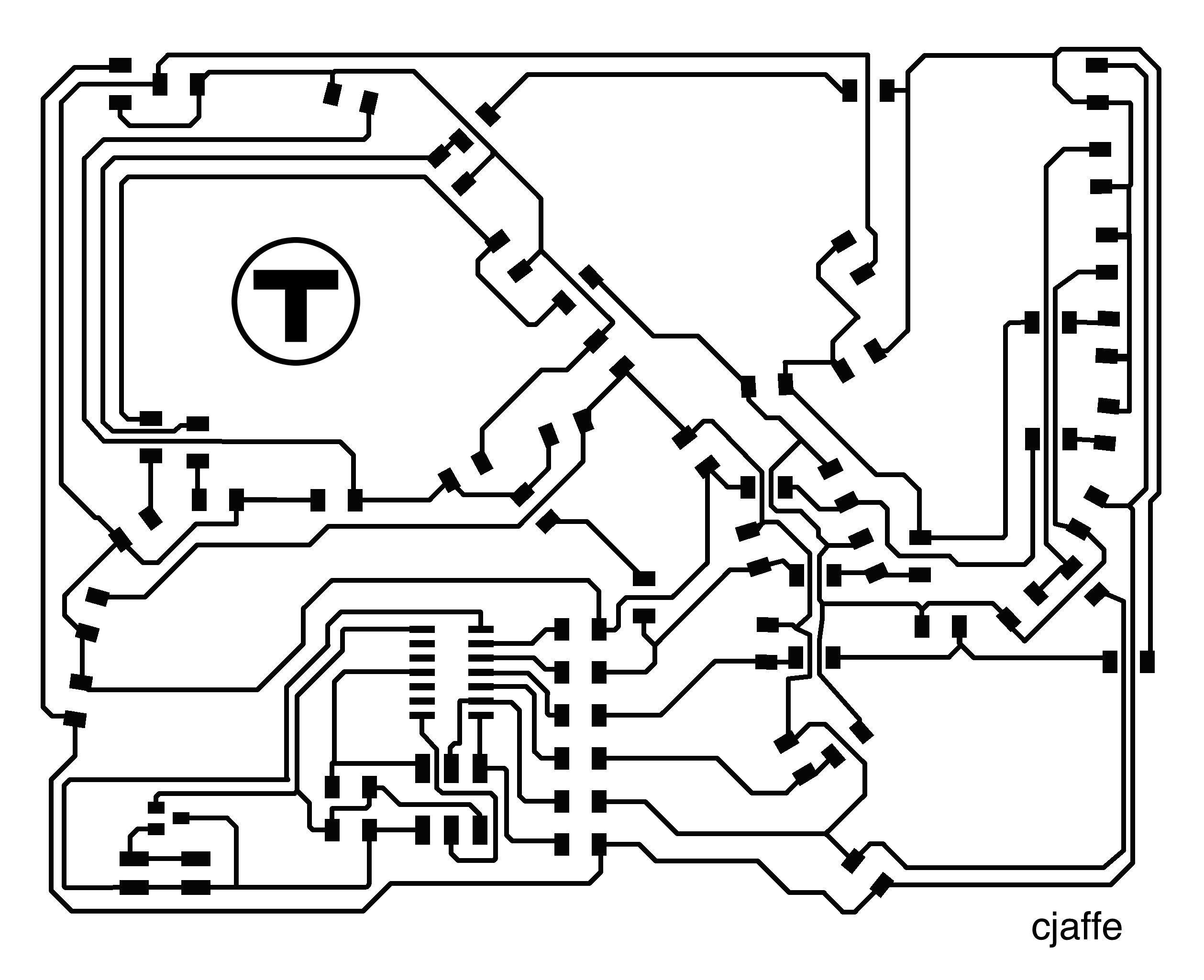
- Use Charlieplexing to design an LED array in the shape of the Boston T map (or at least some portion of it...red, green and blue lines?). I thought Charlieplexing looked really cool and I also love the design aesthetic of subway maps, so this seemed like a good way to combine the two.
- A capacitive touch sensor that controls a small motor or servo. The readings from the touch sensor will be communicated to the motor using Bluetooth. I realize this project is a bit ambitious in that it combines three new ideas, but they are all things I want to learn about so I figured I'd give it a go. I'm hoping to use some sort of capacitive touch sensing for my final project, so this seemed like good practice. Given my experiences with other project cycles, I will be sure to include a number of LEDs on each board for debugging purposes.
Before I designed anything, I wanted to familiarize myself more with the technologies/ techniques I planned to use. Here is some information (hopefully at a HTMAA-appropriate level) about some of these technologies:
Charlieplexing:
- Sources: Maxim Application Note, Wikipedia, Charlieplexing design tutorial
- Charlieplexing is a technique for driving a multiplexed display in which relatively few I/O pins on a microcontroller are used to drive an array of LEDs. (from Wikipedia).
- N pins can drive (N^2 - N) LEDs
- Each LED is drive by a unique anode-cathode pin pair. That is, if LED #1 has its anode on Pin 1 and its cathode on Pin 2, no other LED will have those same pins as its anode and cathode. Therefore, you can selectively apply the correct LED-driving voltage to certain anode-cathode pairs to light up specific LEDs.
Capacitive Touch Sensing:
- Sources: Instructables, Arduino CapSense library, Sam Spaulding's Input Devices project, Dan Chen's Output Devices project
- A capacitor is a device for storing charge, often made up of two parallel plates with opposite charges. Capacitance is proportional to the area of the plates and inversely proportional to the distance between the plates. You can create a capacitor using the sensor plate and your finger.
- In practice, touch is measured using a step response: that is, when you put a signal on a "send" pin to the sensor, how long does it take for a "receive" pin to also change state.
- From the Arduino CapSense library page: "The delay between the send pin changing and the receive pin changing is determined by an RC time constant, defined by R * C, where R is the value of the resistor and C is the capacitance at the receive pin, plus any other capacitance (e.g. human body interaction) present at the sensor (receive) pin. Adding small capacitor (20 - 400 pF) in parallel with the body capacitance, is highly desirable too, as it stabilizes the sensed readings."
- Based on my sources, I felt like I could either go the route of using the CapSense Arduino library, or using Neil's code for ATTiny45 from the Input Devices week. I thought I'd go with the CapSense library, since it abstracts the sensing code a bit more. Since I'm trying to do a lot of things this week, having the help of a library seemed like it could simplify things a bit.
- Based on the CapSense documentation, it looks like I will need 2 pins: a send pin and a receive pin. These pins should have a resistor between them. The receive pin will be attached to the sensor "plate". The receive pin can also have a small capacitor between it and ground which will help with stability. Here's a diagram (from CapSense documentation) of what this circuit will look like:

Bluetooth:
- Sources: HTM Bluetooth Tutorial, Instructables BLE-controlled lamp, BLE Video Tutorial, a helpful discussion with Thras
- Bluetooth is a wireless technology standard for exchanging data over short distances from fixed and mobile devices, and building personal area networks (PANs). Invented by telecom vendor Ericsson in 1994, it was originally conceived as a wireless alternative to RS-232 data cables. (from Wikipedia)
- A BLE device may operate in different modes depending on required functionality. The main modes of operation are called the advertising mode, scanning mode, master device, and slave device. (from HTM Bluetooth Tutorial)
- In order to establish a connection, one device has to be in advertising mode (and allow for a connection) and the other device in Initiator mode. It is similar to the scanner mode but with the intention to establish a connection. The initiator scans for a desirable device-advertising packet and consequently sends a connection request. Once a connection is established, the initiator assumes the role of master device and the advertiser becomes a Slave device. (from HTM Bluetooth Tutorial)
- For the purposes of this class, we use the HM-10 Bluetooth module which uses the CC2540 chip and needs a supply voltage of 2.0 to 3.7 volts. There is a breakout board that makes it easier to connect to a FTDI cable. The breakout board gives you V, GND, and Tx/ Rx pins. The Bluetooth module can be controlled using AT Commands.
- From my conversation with Thras, I learned more about the logistics of getting the Bluetooth modules to connect to each other. It seems like the Bluetooth modules can be configured by sending commands to set them as Master/ Slave using the software running on the ATTiny. Once they are connected, the communication should be transparent...that is, data sent to the Tx pin on one board will go directly to the Rx pin of the other. It should seem like the boards are connected or communicating directly, without having to worry about the communication layer.
- Thras also mentioned that it's more common to use the HM-10 modules to communicate with a mobile phone, instead of with each other. Most mobile phones have built-in Bluetooth protocol, which is a somewhat more complicated protocol than that used by the nRF transceivers. The nRF transceivers are more commonly used for peer-to-peer communication, whereas Bluetooth is more often used for communication with phones. However, I want to familiarize myself with Bluetooth and I also think it's possible I would want to communicate with a phone at some point, so I thought I'd stick with Bluetooth.
- Here's a rough sketch of what the capacitive touch/ Master Bluetooth module could look like, roughly based on the Hello World board from the Electronics Design week:

Motors (Types, Operation, etc):
- This helpful post succinctly explains the difference between DC motors, servo motors, and stepper motors. Very, very briefly: DC motors spin all the time at a speed controlled by PWM (only requires power and ground inputs). You can control the position of servo motor using PWM (requires power, ground and position inputs). Stepper motors allow you to turn the motor to specific, pre-defined positions or "steps" by turning different electromagnets on and off. Stepper motors require external control circuits.
- A H bridge is an electronic circuit that enables a voltage to be applied across a load in either direction. These circuits are often used in robotics and other applications to allow DC motors to run forwards and backwards. (from Wikipedia).
- It seems like a servo motor is the right balance of complexity for this project. I know there is a PWM pin on the ATTiny44 (if that's what I end up using), and it seems like I could try correlate the amount of pressure measured in the touch sensor to the angle of the servo motor.
- Here's a rough sketch of what the servo motor/ Slave Bluetooth module could look like, roughly based on the Hello World board from the Electronics Design week:

After all of this investigation, I thought I would jump in by trying to design a board with a charlieplexed LED array output in the shape of the Boston T map. This seemed a little easier since it only involved one board, and I could modify Neil's design. I thought I'd use 6 pins so that I could have 6*6 - 6 = 30 LEDs, 10 for each the Red line, Green line, and Blue line.
As usual, designing the board took way, way longer than anticipated. I should have realized this, but I do think it's easy to delude yourself about the amount of work required when you're really excited about a project. I designed the schematic and board in Eagle, using some of the tips and tricks I'd picked up in Week 5. I was more comfortable with the basic mechanics of using Eagle, but laying out all the LEDs for the Charlieplexed LED array took a very long time, since there are a lot of traces to route and I wanted to have the LEDs in a particular pattern. I ended up having to use about 10 jumper resistors to be able to route everything the way I wanted. I'm not sure there's any way around this, short of using a two-layer board or exactly following one of the established Charlieplexing layouts. In any case, I finally got a board design I was happy with. There were a few clearance issues when I had a jumper trying to cross two traces, but I plan to check for those after milling and make manual corrections if needed.


Next up: milling and stuffing the board. As usual, this did not go as smoothly as anticipated. I'd heard that the Modelas were having some trouble, so I milled a few test boards before starting my (giant) board. These test boards, pictured below, had a ton of burrs and the cuts were really deep. Acceptable, but pretty ugly. Will came to help me troubleshoot the Modela, and thought that there was a spindle problem (I believe he has since replaced the spindle/ fixed the problem). In lieu of using the MRX-20, he taught Andrew and I how to use the SRM-20 (another milling machine which is in the same machine shop as the ShopBot). The procedure is roughly the same, except that you need to set the permissions manually (type "sudo chmod 777 /dev/usb/lp0" in a terminal) and the zeroing process for the z axis is slightly different. You get the endmill close to the stock using the z0 parameter in fab modules (instead of using a button on the board), and then lower it manually. You also need to "trick" the machine into thinking it's closed by placing a pin in the door sensor in the upper right hand corner. This allows you to make the manual zeroing adjustment and still allows the machine to receive signals. I used all the default settings, except for cut depth. I set cut depth to .13mm because we noticed that the bed was uneven and the cuts weren't deep enough on one side.


The board took almost 1.5 hours to mill, but when it was finished, it came out beautifully. Next, I very, very carefully and painstakingly stuffed the board. Even though I've gotten a lot better at stuffing boards, it took me ~2.5 hours because I wanted to be sure that I wasn't shorting anything and that all my LEDs were oriented correctly. I also needed to be extra careful about soldering my jumper resistors. For each LED, I needed to check its orientation against my board design to make sure the anode and cathode were connected to the correct pin. Though it took a long time and required great attention to detail, my only real trouble during this phase was tracking down the correct LEDs...the basement shop was out of red and blue LEDs. I was able to find a few red LEDs, and ended up using "blueish white" LEDs for the blue line.


I programmed the board using the command line toolchain discussed in Week 7. I downloaded Neil's Charlieplexing code and modified it to add another pin and change the order in which the LEDs are flashed. After connecting everything up, I used the following commands to program the board:
- make -f hello.array.44.make
- sudo make -f hello.array.44.make program-usbtiny-fuses (possibly not necessary since my FabISP was already setup to program an ATTiny44?)
- sudo make -f hello.array.44.make program-usbtiny
Lo and behold...after programming the board, it works!! This is a happy moment. I played around with a few different light speeds, but preferred just having the lights change at one slowish, steady speed. I noticed that two of my "red" LEDs are actually green. If I'm able to track down some more red ones, I'll swap them out tomorrow. Otherwise, I'm just really happy this works!

I unfortunately ran out of time and wasn't able to work on the Bluetooth/ capacitive touch/ servo project. However, I think I laid good groundwork for that project this week, and will hopefully be able to work on it more next week (it could work as my Input Devices project because it involves capacitive touch sensing!)
Update 11/24/2015: I switched out 12 LEDs so that the red line was completely red and the blue line was actually blue. Happily, the board still works great after making these switches...
Design Files & Code
- charlieplex-board.png
- charlieplex-traces.png
- hello.array.44.c (adapted from Neil's version)