Skutt Kilns | AVR microcontroller | Type S thermocouple | MosFet | OpAmp | Arduino (C) | Processing (java)
I have been working on the Mediated Mattter glass 3D printing project for a little over 6 months. As I proposed in the first week, I wanted my final project to be something that would improve the development of a new, larger, and more reliable glass printer. One aspect of developing a novel fabrication platform that has frequently slowed research is the constraint of control systems that were not designed for the kinds of fabrication we work with. Because of the high energy cost in heating glass to its working temperature, as well as the safety hazards associated with it, thermal cycles of glass processes are always slow, and deliberate. Many glass furnaces are designed to be kept on indefinitely, only lowering temeperatures enough to help with the energy cost during off hours, but never going low enough for the glass to solidify.
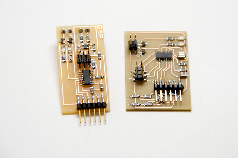
The glass printer has 3 kilns. One is for the crucible where molten stock is held. One is for the printing environment, a large annealing kiln, low on temperature but high on surface area and of course volume. The final kiln is in between and occupies only 3 inches of height. It's job is to precisely control the temperature of the nozzle (printhead). The first two are adaptations of off the shelf kiln products. The nozzle kiln is slighly more custom in form, as it has no formal structure, only element wires that surround the nozzle and fit snugly between the nozzle and the annealer's insulating roof. All of them have similar control systems. While it is fairly easy to restructure commercial kiln products by physically removing walls, creating openings for nozzles or build plates, etc, the controls require a feedback system and on board powersupply to correclty output wattage per surface area. This is the only way to reliably translate electrical ouput to soak temperature. As these are design for a glass industry whose processing timescales are on the order of days and weeks, the available kiln programs require to at least define the temperature profile for the day. Controllers allow you to set ramp speeds and hold times sequencing about 8 or 10 of each, easily enough to set your glass shop going for the week. When a 3D print takes less than 30 minutes and paramaters need to be changed on the fly, these controllers become increasingly cumbersome. In the best case, they have a facility for raising the temperature during a holding sequence by 5 degrees at a time, but none have the ability to even go down by 5 degrees. The ability to specify a temperature arbitrarily to account for process changes is simple but essential. For my final project, I built a custom circuit board from scratch which could accomplish this task.
The first task was to decipher the commercial kiln controller to find out exactly how it was powering the heating elements. These products are actually quite clever in that they can run off of a wall outlet and can power something as substantial as a large glass furnace, as well as a circuit board with LCD interface. The controller takes the wall voltage and powers an onboard DC power supply. This sends voltage through a tranformer to two relays, one mechanical and one solid state, as well as through a further tranformation down to logic voltage to power the board. The board uses a mosfet circuit to power both relays, and the relays connect the first tranformer's voltage (in this case 12V) which goes to the heating elements only when both relays are closed.
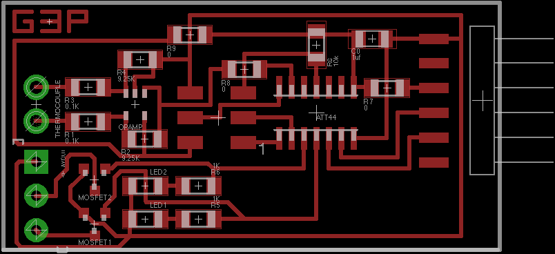
I knew then that I did not need to be able to modulate my own 12V supply but could run a similar circuit on top of the original one, using the same technique to regulate the voltage through the relays. Previously I had used logic voltage to control smaller separate relays during the output devices assignment, but this time I simply added 2 n-mosfets to my board, controlled by two output pins on the ATTiny44, along with 2 indicator LEDs running in parallel. They would connect the ground from each relay to the ground from the 12V tranformer when the pin was addressed. The critical part of this method was a toggle switch to ensure that when I wanted my mosfets to be in charge of the relay as opposed to those from the commercial board, they would never get overriden. This doesn't affect when I wish to increase the temperature and turn the elements on when they would have been off, but does when I need to do the opposite.
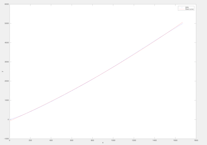
Next was the feedback in the form of a high temperature, type S thermocouple. I had experimented with this during the input devices assignment, but made no attempt to actually calibrate the thing and was only lookingto see that it produced enough voltage through the opamp circuit to read at all. For the final project I took it several steps further. I implemented an index in MATLAB of the voltages at every temperature and fit a function to the data. I then calculated the proper gain for the OpAmp and procured some resistors with less generic values so that it mapped exactly from 0 to 5 volts. I also added screw headers so the thermocouple wires didn't need to be spliced onto a pin header connection which, because of the different metal, can apparently create sensor errors.
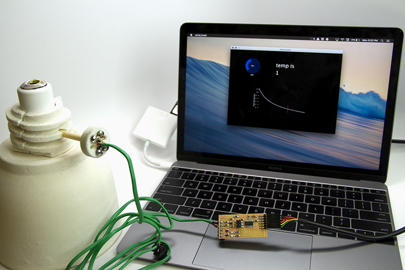
Finally I had to implement the controls interface. In the most recent assignment on interfaces I used a library in Processing called ControlP5 to make a simple slider that the microcontroller could read, and I demonstrated that by simply making it the declared blink rate for the board's indicator LEDs. For the more serious application, the user needs to be able to see the temperature, declare a desired temperature, and ideally, be able to visualize what effect this has on processing. So, the new interface has the slider/knob to control desired temperature which doesn't map to blinking frequency but is fed to a new code for the microcontroller that checks the real thermocouple temperature reading once every 30 seconds and turns the elements off if it's too hot, or turns them on if it's too cold. Just empirically, we noted that the cycles of the elements while they're controlled with the commercial box, were about this long. It seems that they take tens of seconds to get hot enough to effectively radiate, so trying to modulate their voltage any faster would be ineffective.
The interface also now reads the temperature from the board throuh the serial cable, and can display for the user what that is. Technically this isn't necessary when you've defined a temperature and know that the board will get there at some point, likely within minutes given the working ranges, but it obviously makes sense to have it be displayed as well.
Finally, the interface displays the viscosity temperature relationship for the glass chemistry we're working with, and can be adjusted as the chemistry is adjusted. The platform is for digital fabrication of a material whose properties go far beyond those intrinsic to the composition. A glass artist can feel that temperature and its rate of change dramatically affect the processing, and so for the new digital glass working interface the user can see the effect on viscosity as they specify working temperatures.