ELEPHANT EMPATHY
WHAT would it feel like to sense even the most subtle vibrations through your feet? Elephants do this-- they are thought to communicate over long distances (miles!) using seismic signals. This project aimed to give us a glimpse into this experience... can you imagine being aware of the smallest vibrations through an ultra sensitive foot?
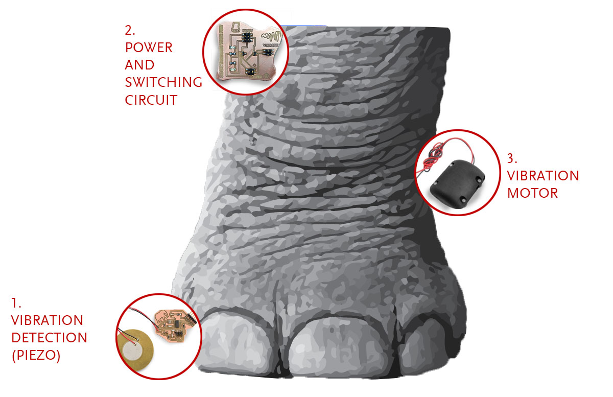
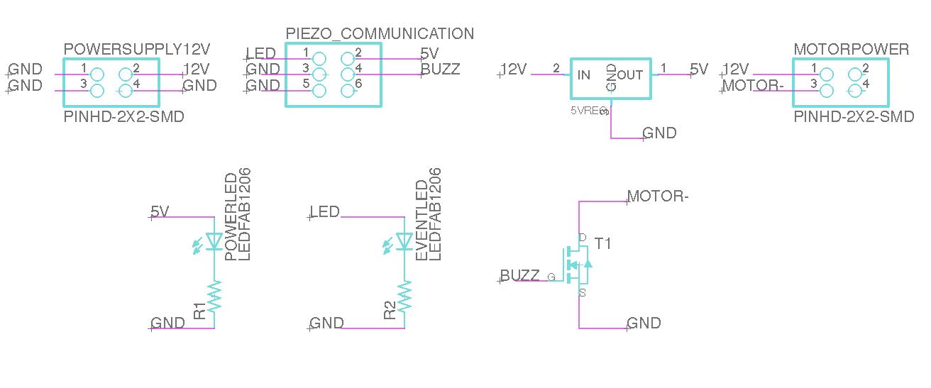
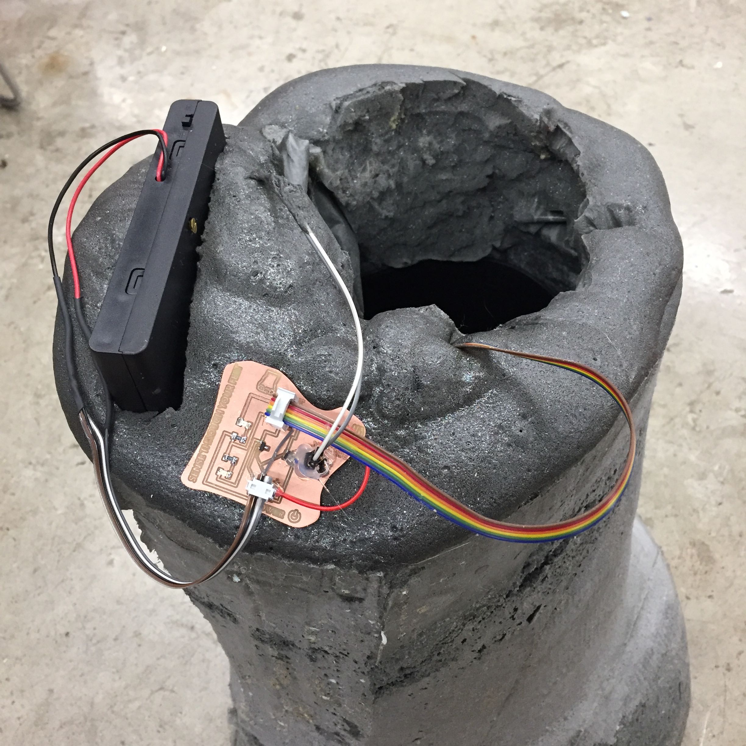
Here was my basic design. There were two boards: one down in the foot by the piezo detector (made in earlier week), and a power/switching board at the top to control current to the vibration motor as well as to the lower board/chip.
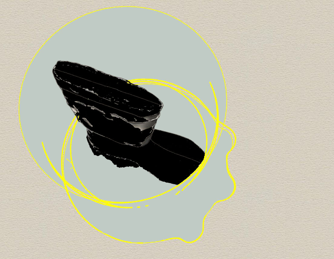
My first attempts to design the foot involved radially rotating a cutout of a foot in photoshop. I liked how the design was based on real photograph of an elephant foot, but real elephant feet weren't fully radially symmetric as in the model...
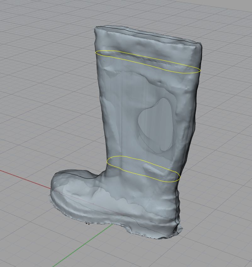
Nevertheless, I first went ahead and modeled toenails (using MeshMixer- software from Autodesk I previously mentioned) on the end of the above-generated .stl file. I also 3-D scanned a big rubber boot (using 123-catch) that I planned to eventually insert inside the cast. This would defend space for someone to 'wear' the foot.
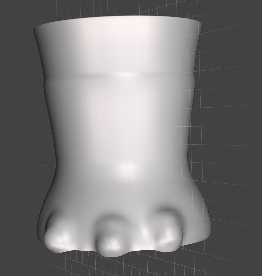
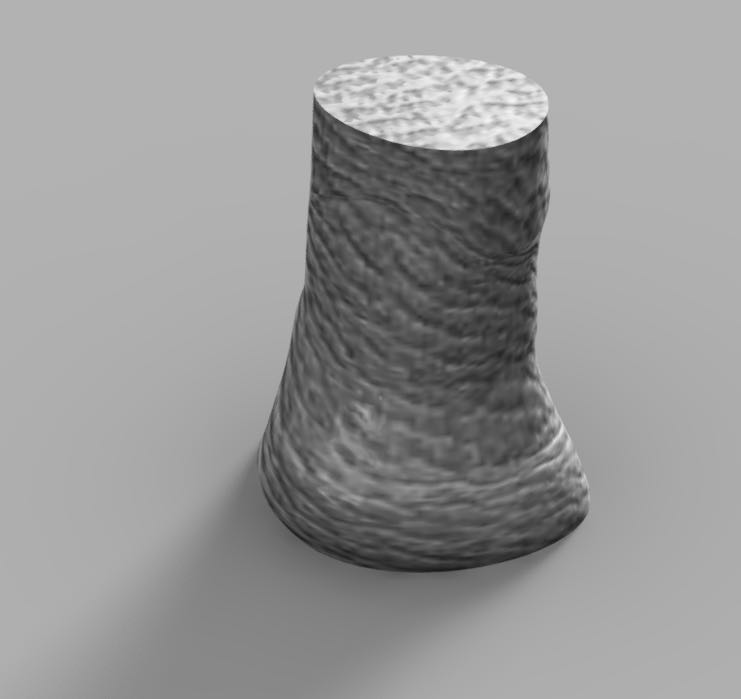
Eventually I redesigned the foot in Fusion360 using the option to trace planar standards and then draw rounded curves through these orthogonal planes. These curves were then 'lofted' to give the organic, sock-like elephant foot!
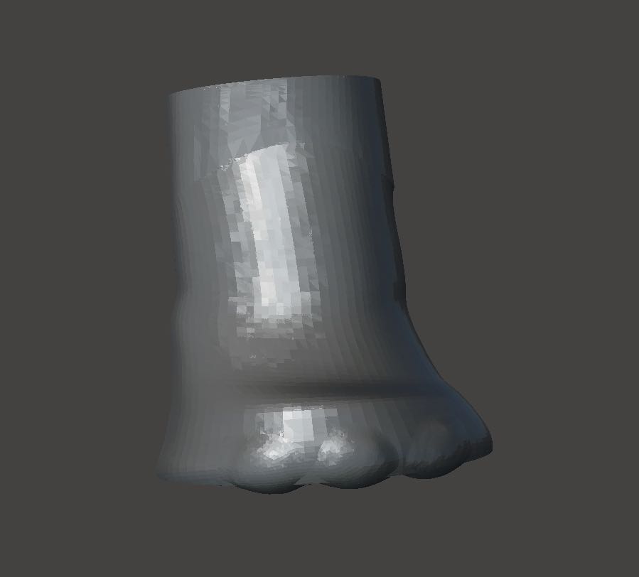
Here are two new versions of the design, one with an imposed 'skin' that looks quite elephant-y. The second has some attempt at toenails.
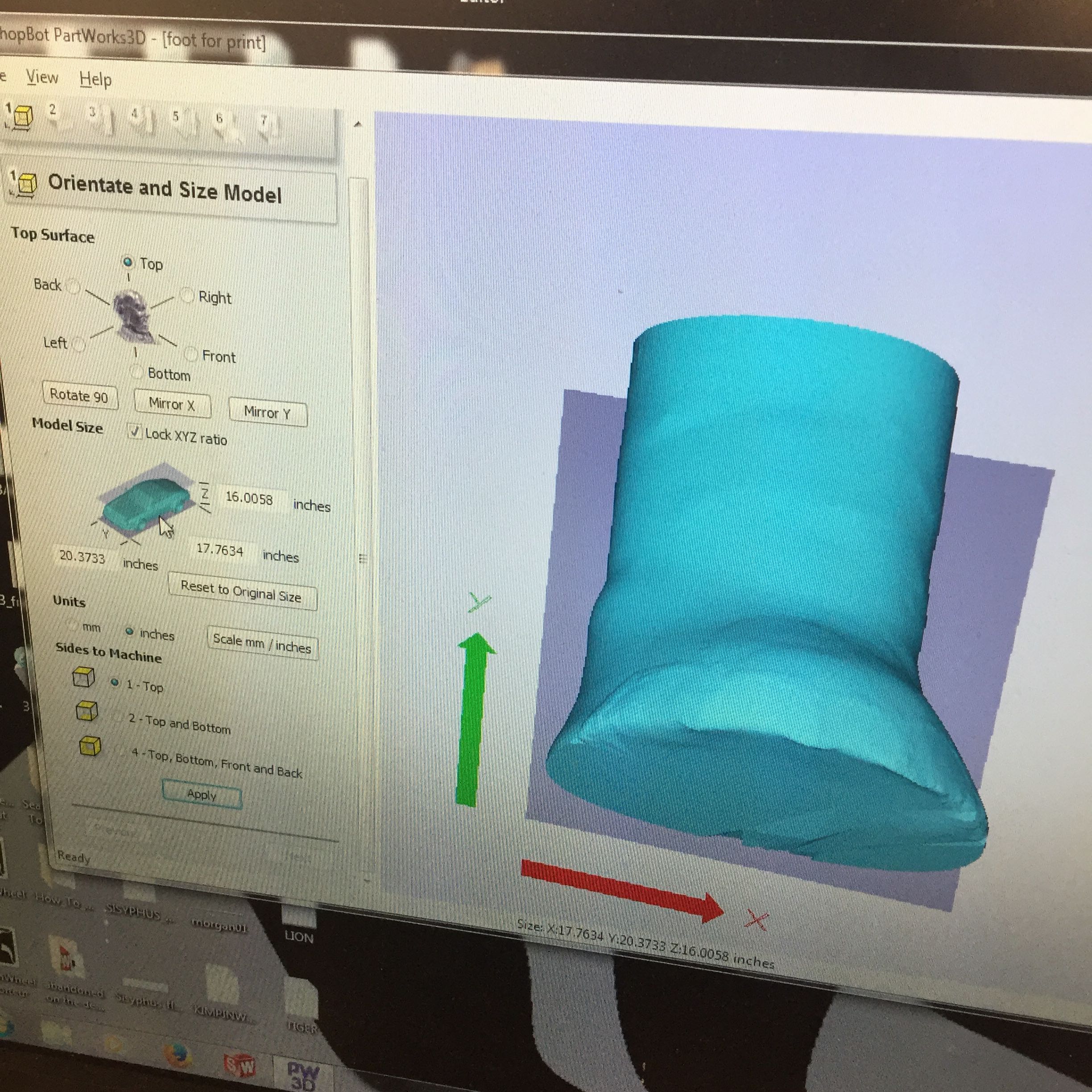
Ultimately, when I went to mill the foot in foam on the ShopBot, the PartWorks3d software did not want to allow me to easily slice the stl into multiple layers or decide which side I'd like to mill from (when opening sections, the top surface dialogue in upper left is greyed out.
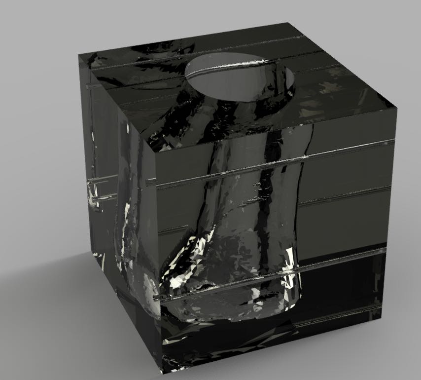
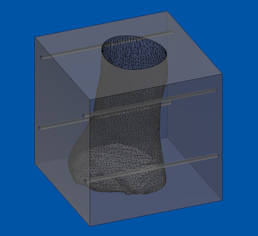
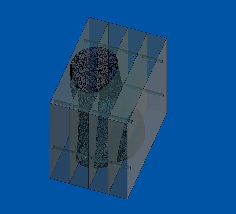
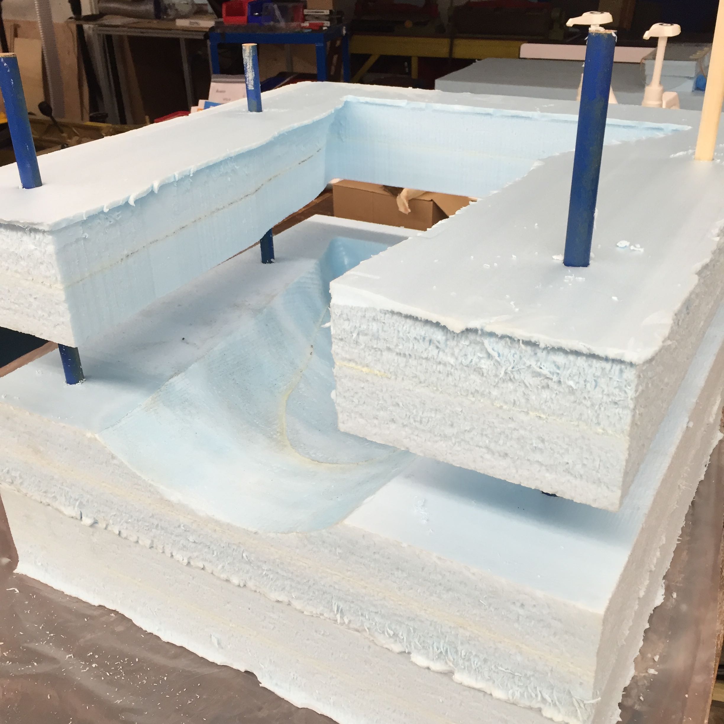
I used a boolean operator (cut) to subtract the foot from a background cube. I also subtracted some models of long dowels to lock registration between the 4 slabs.
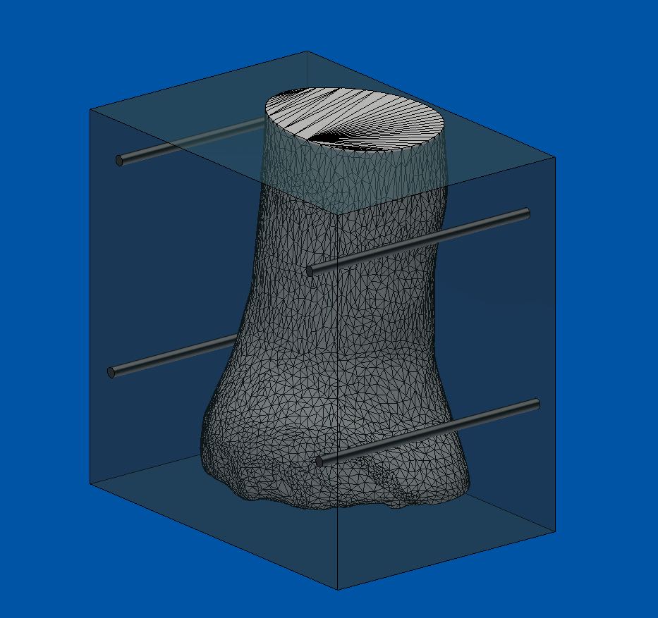
In my initial model, I'd accidentally created a true cube (LxWxH), whereas my millable area is much smaller: 4 inches per slab (each made of 2x 2 inch fab) times 4= 16 inches thick (rather than the 24 width+length of the surface area).
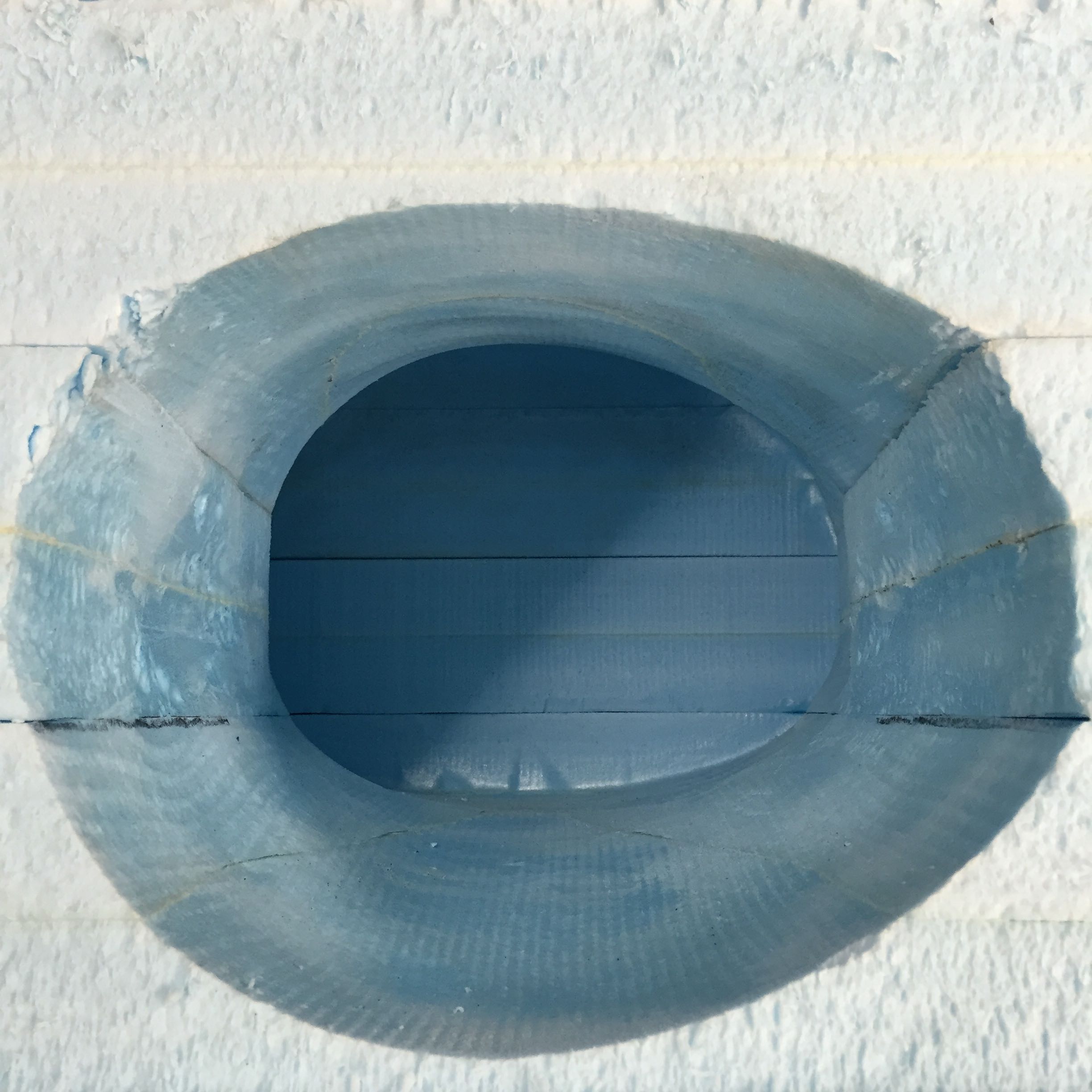
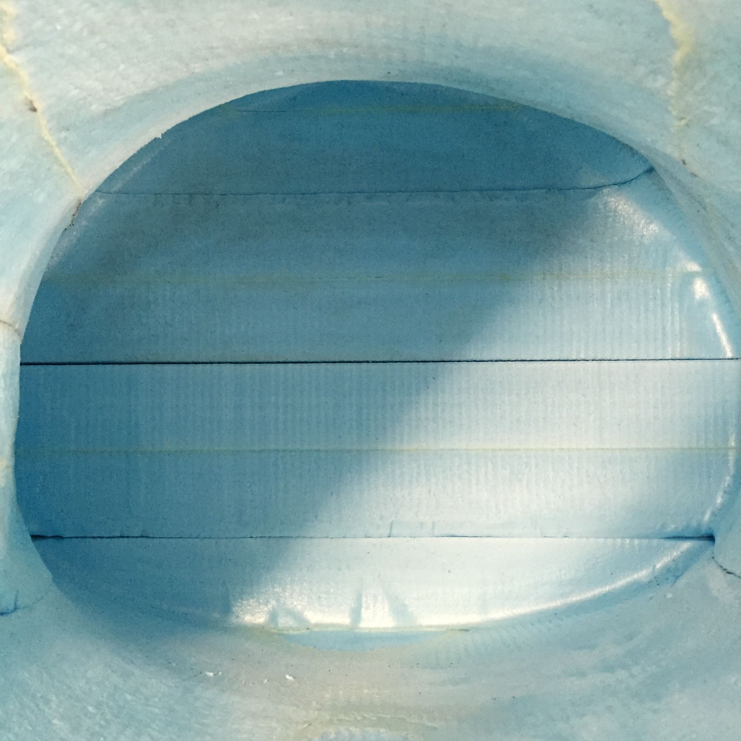
Here is one of the four slabs.
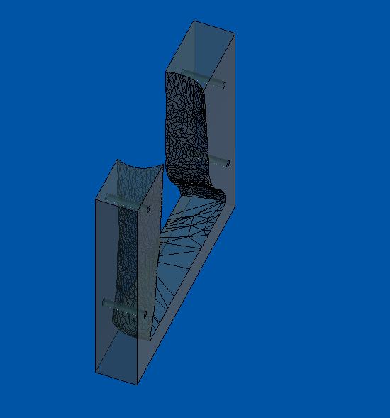
All the slabs together.
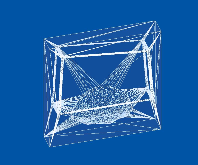
Exporting a slab as an .stl file (for PartWorks3D).
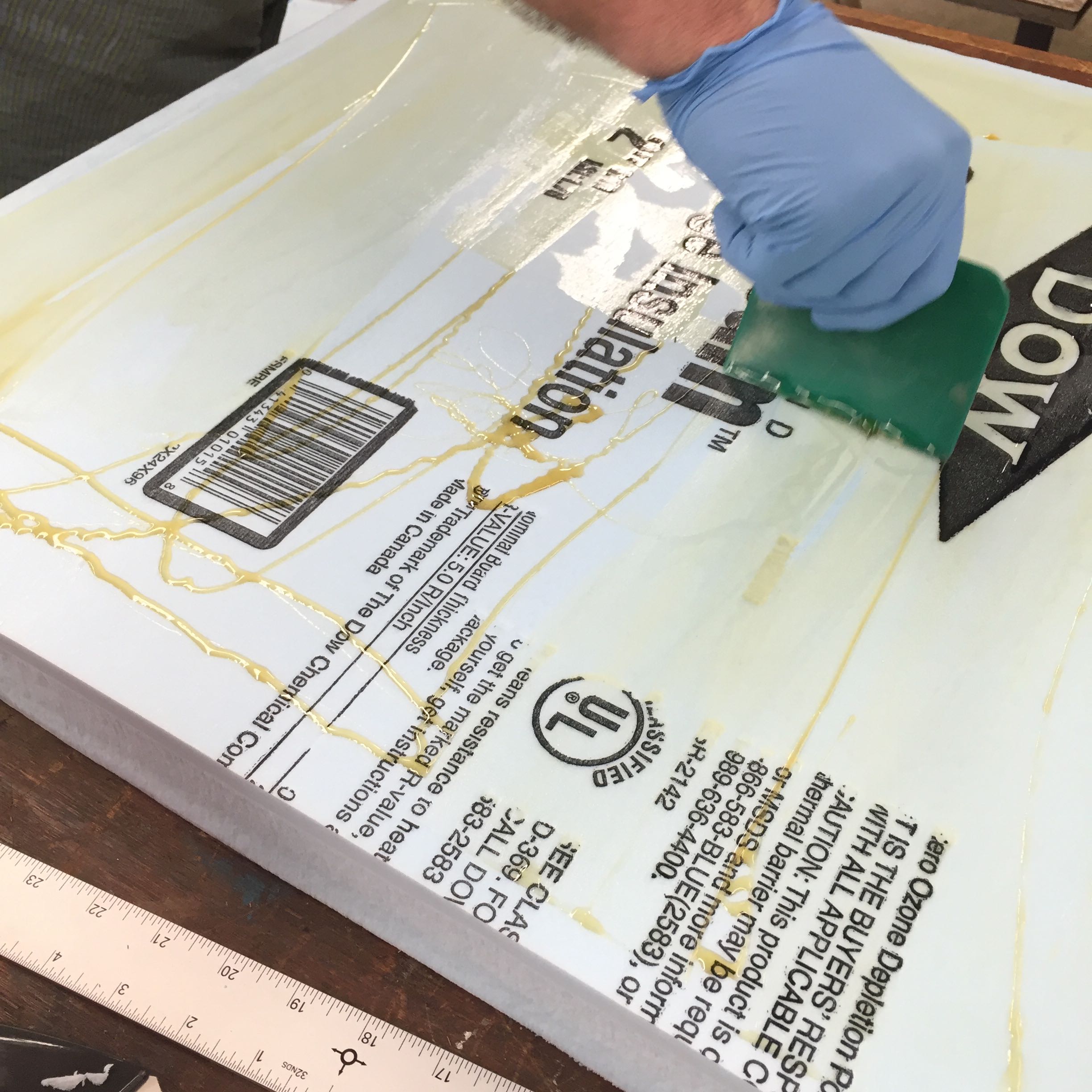
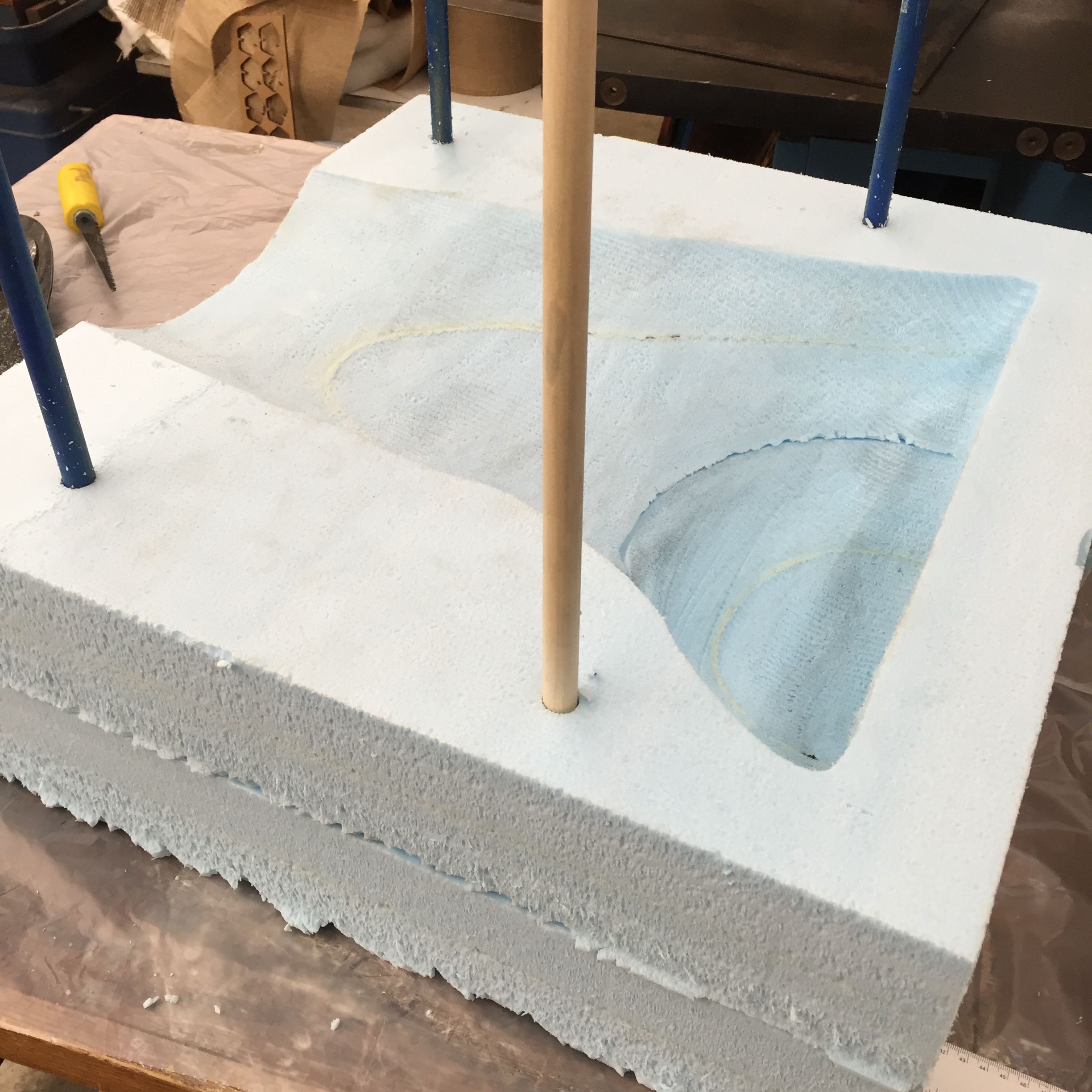
Preparing foam for cutting: gorilla gluing layers together...
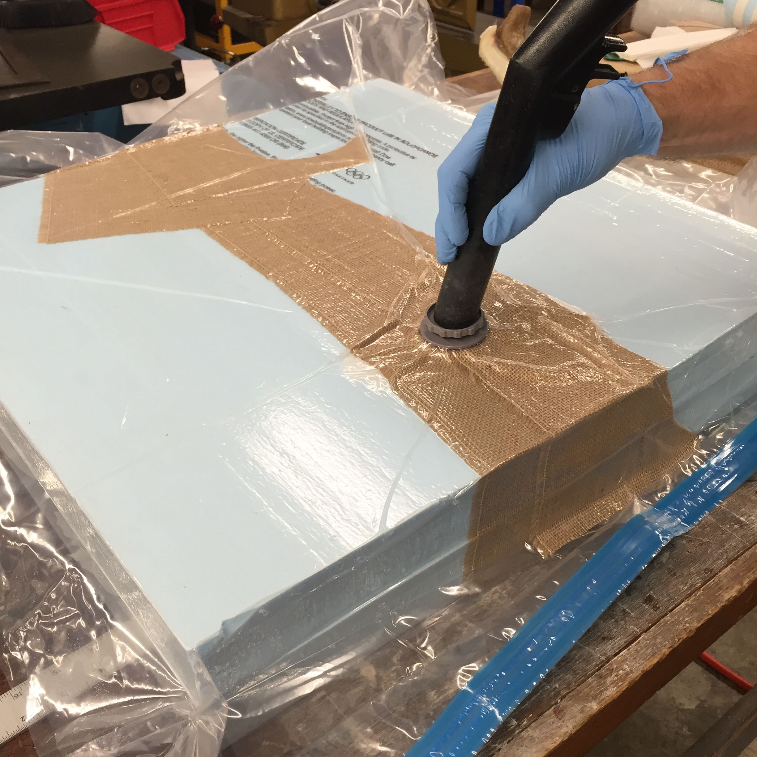
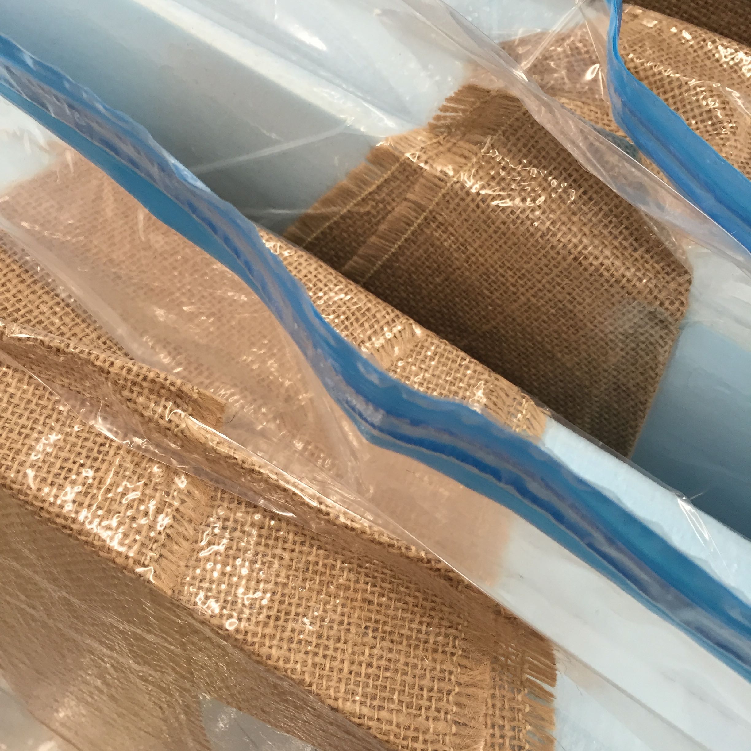
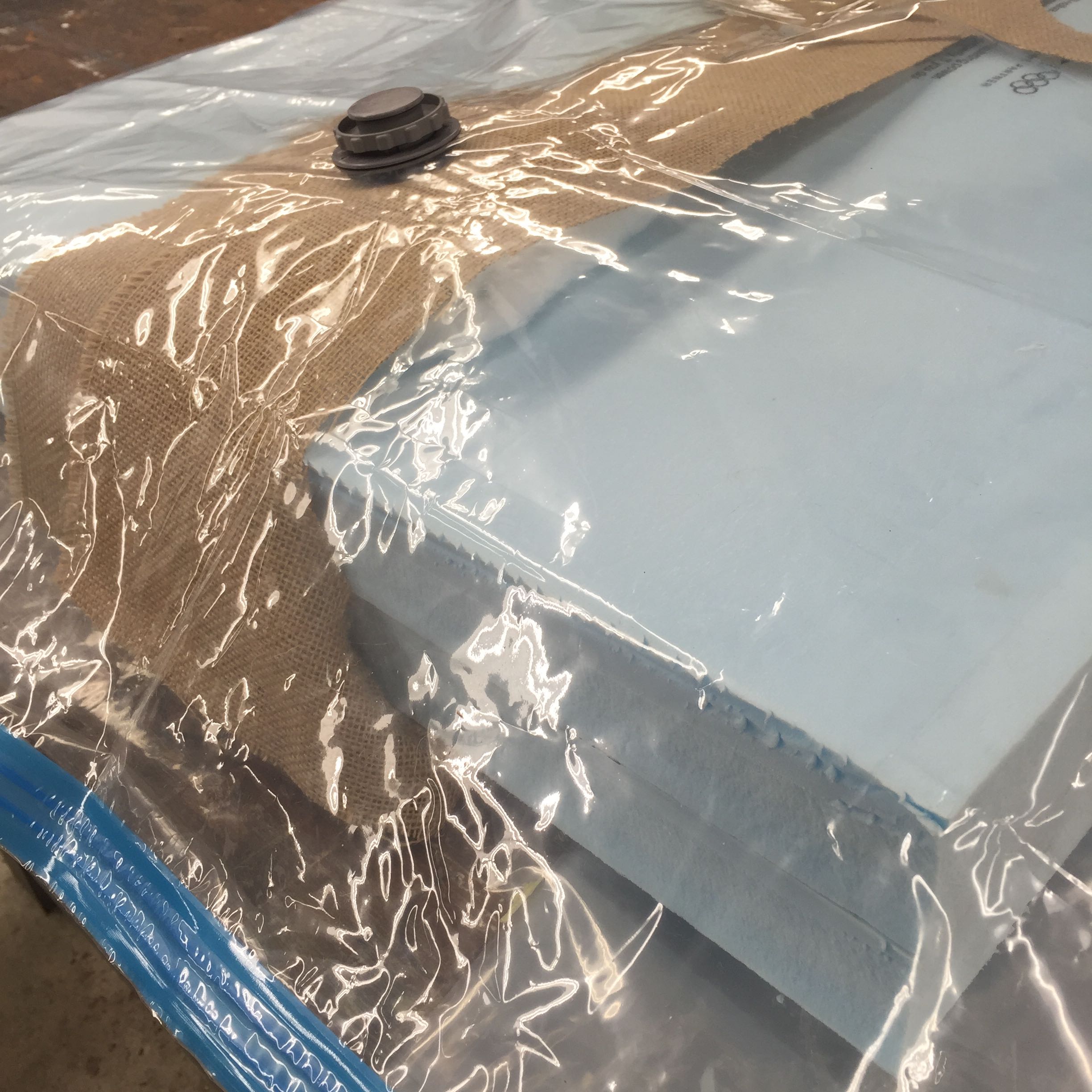
...and applying a vacuum seal to get even pressure throughout. Thanks to Daniel (again!) for expert help and technique-sharing!
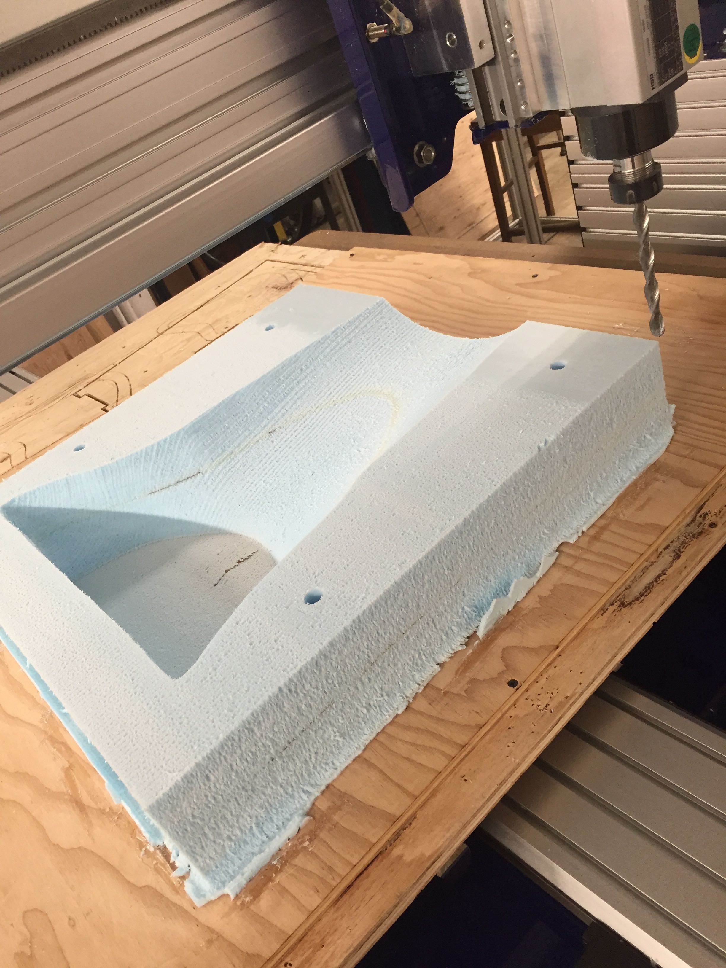
Here's the cutting in business. About 35 minutes timelapsed here... showing final raster-style finishing pass and exterior cut at the end.
Same thing just a little slowed down...
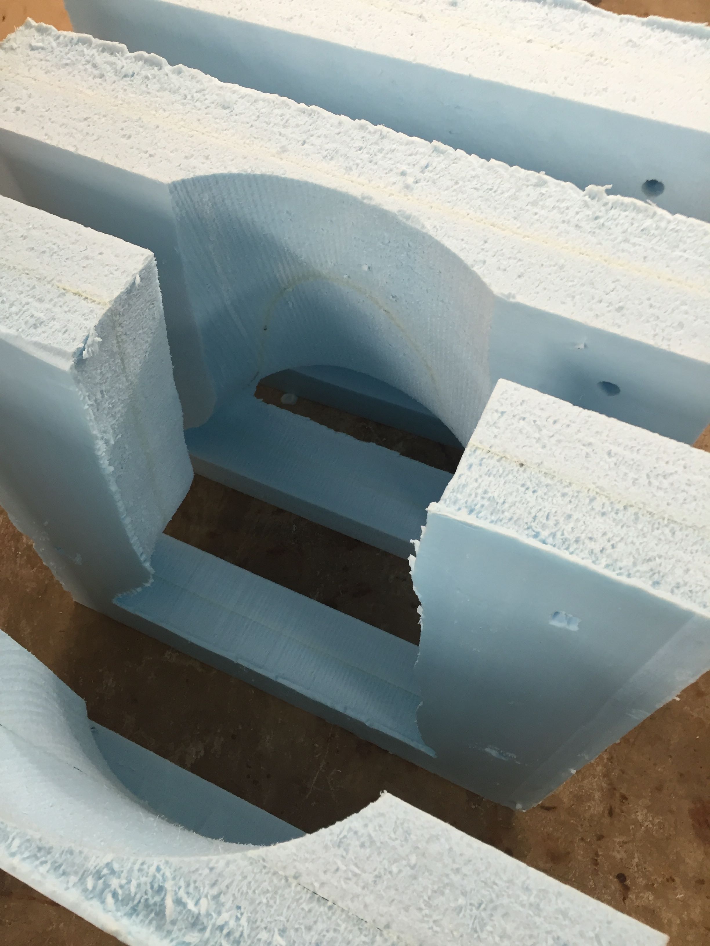
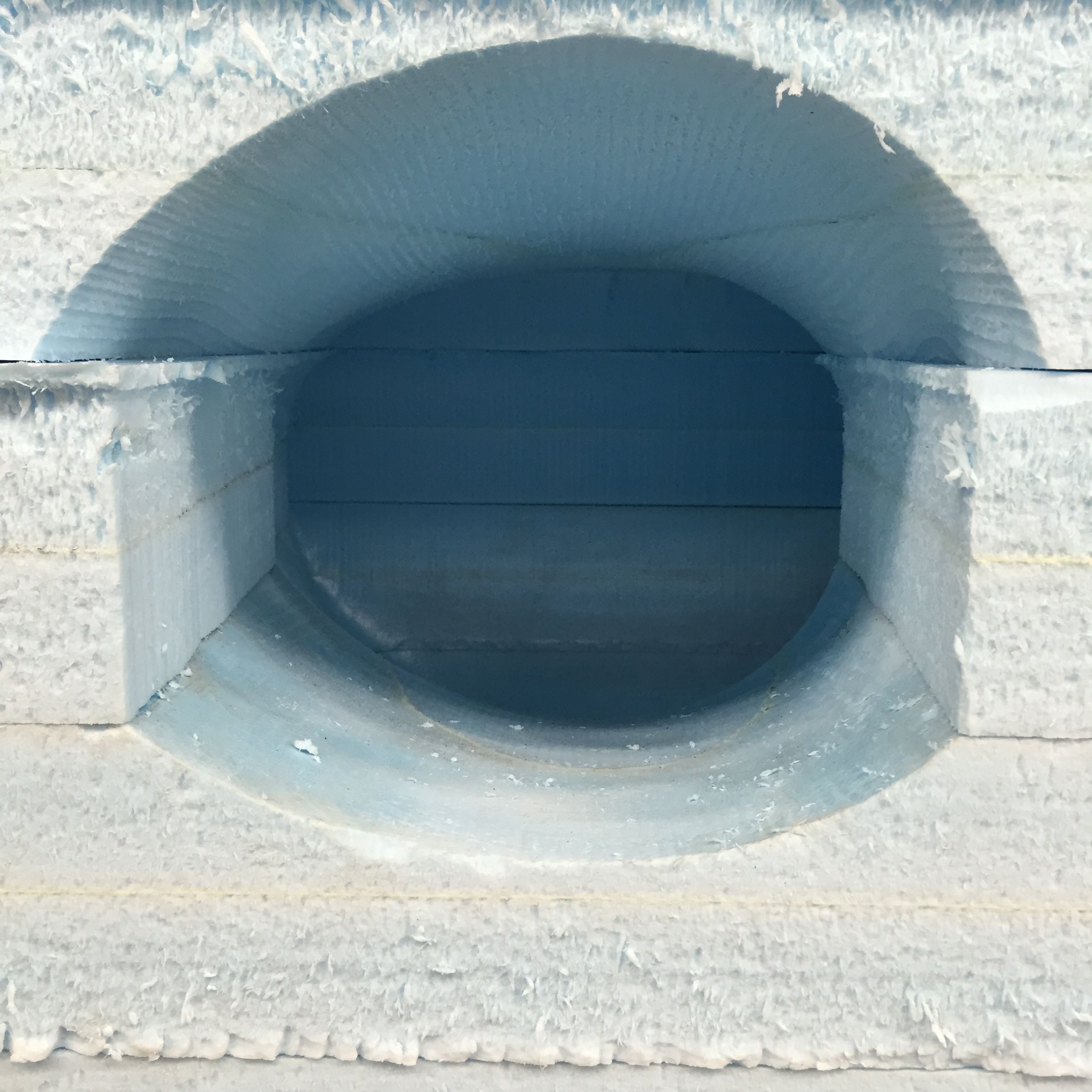
As the slabs are completed, I put them together using the machined holes for aligning wooden dowels.
One of the slabs unavoidably required 'touch-up' because of some overhangs. This couldn't have been prevented by milling from the other side- just overhang either way.
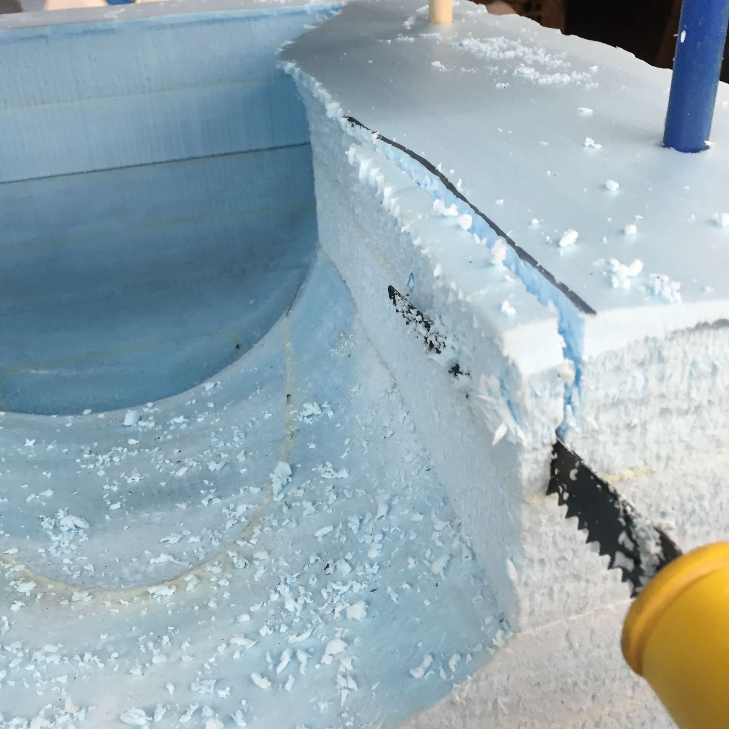
Luckily a very quick fix with the coarse handsaw.
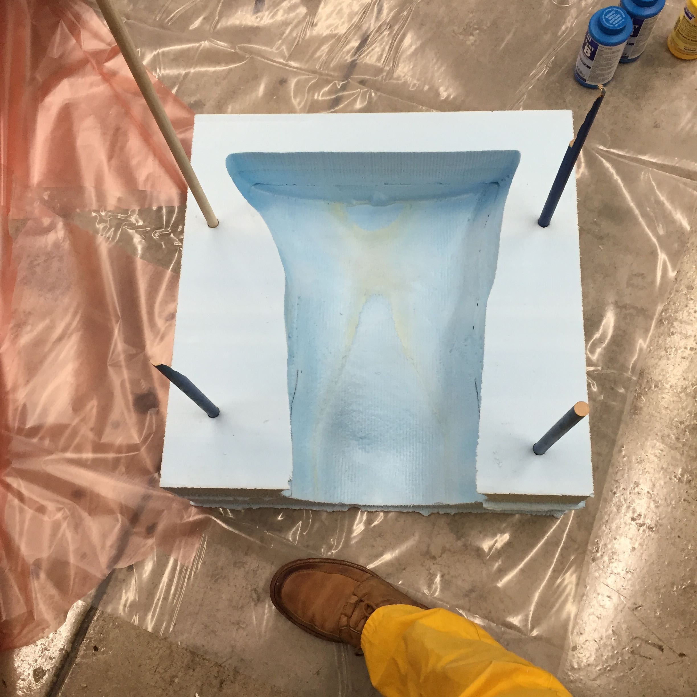
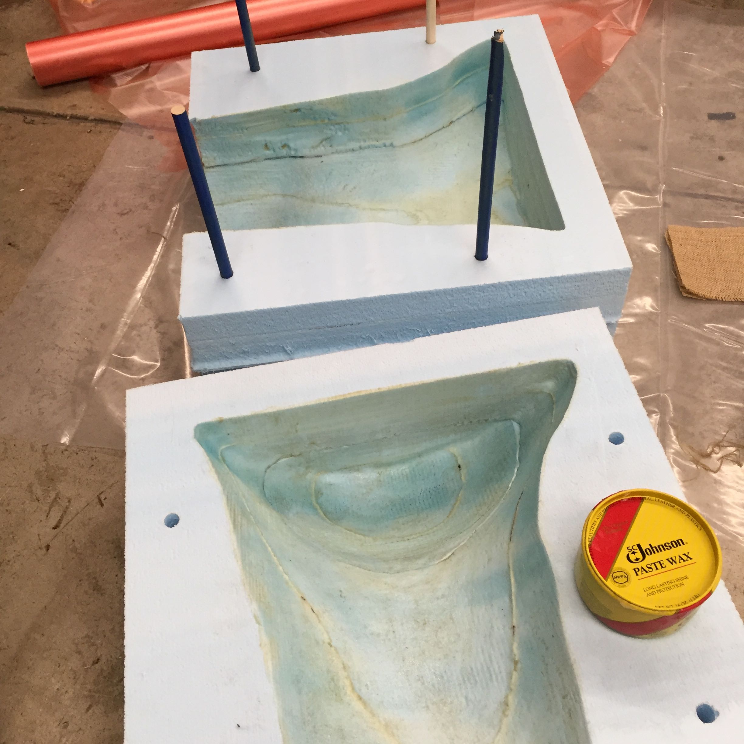
To prevent sticking of the cast to the mold, I lined with Johnson's Paste Wax. Not the most pleasant compound, but seems very slippery.
Mold is ready for casting.
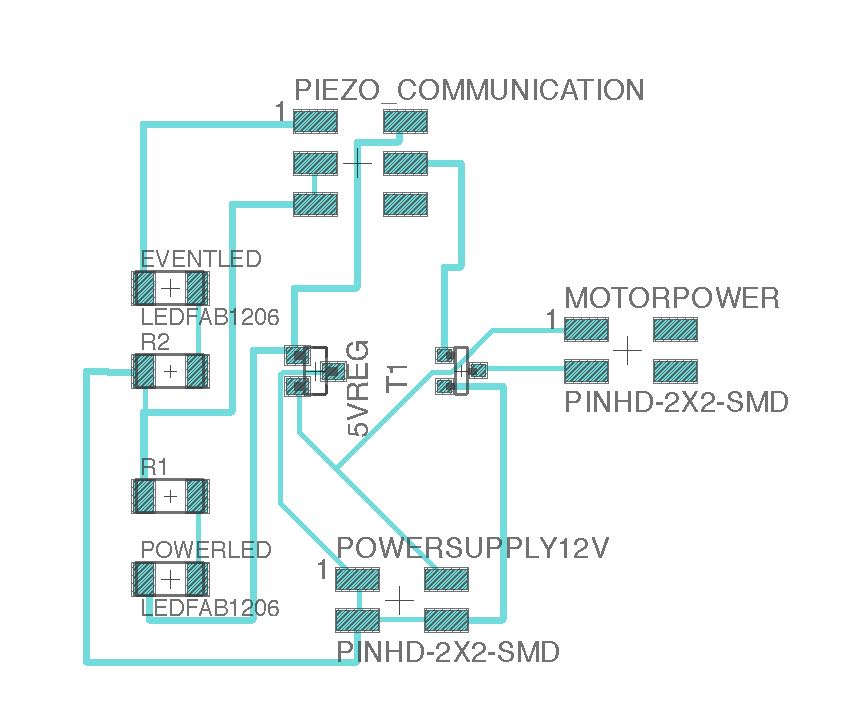
Development of electronics for relay breakout board.
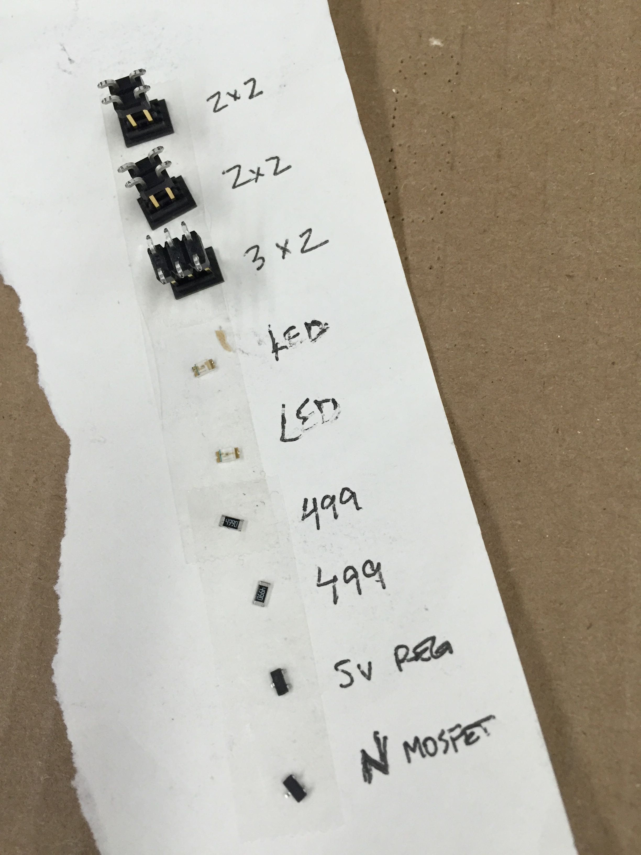
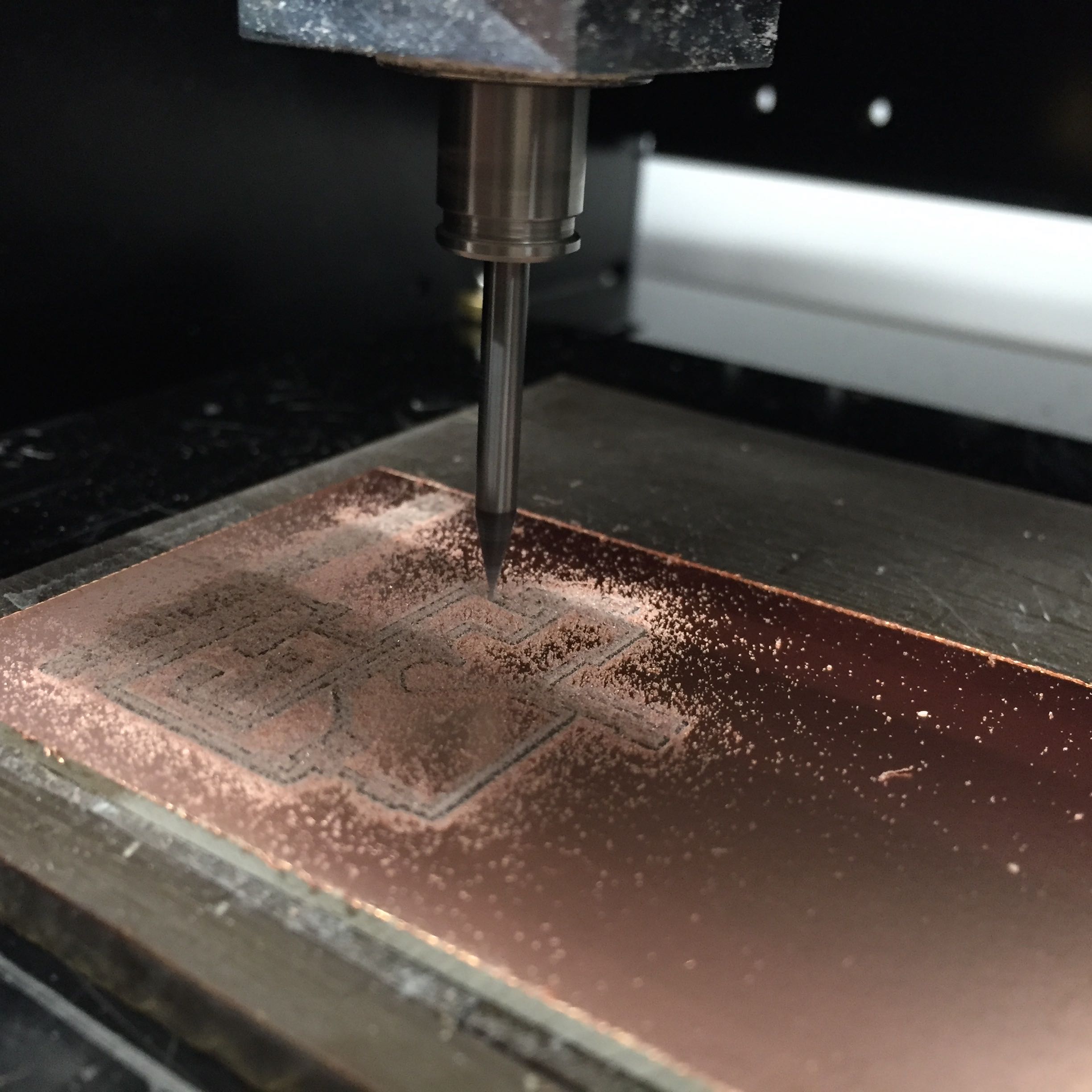
Very thin traces on the board- I would have liked to redo with thickertraces, particularly around the MOSFET and 5V regulator.
Here is the $8 vibrating 12V motor from Amazon being placed in a glove to allow it to be cast inside the foot.
Now it was time to work on the mold itself. Sam suggested a material called FoamIt, andit turned out to be the perfect medium. It cost $28 per container and expands to 14x its original volume.
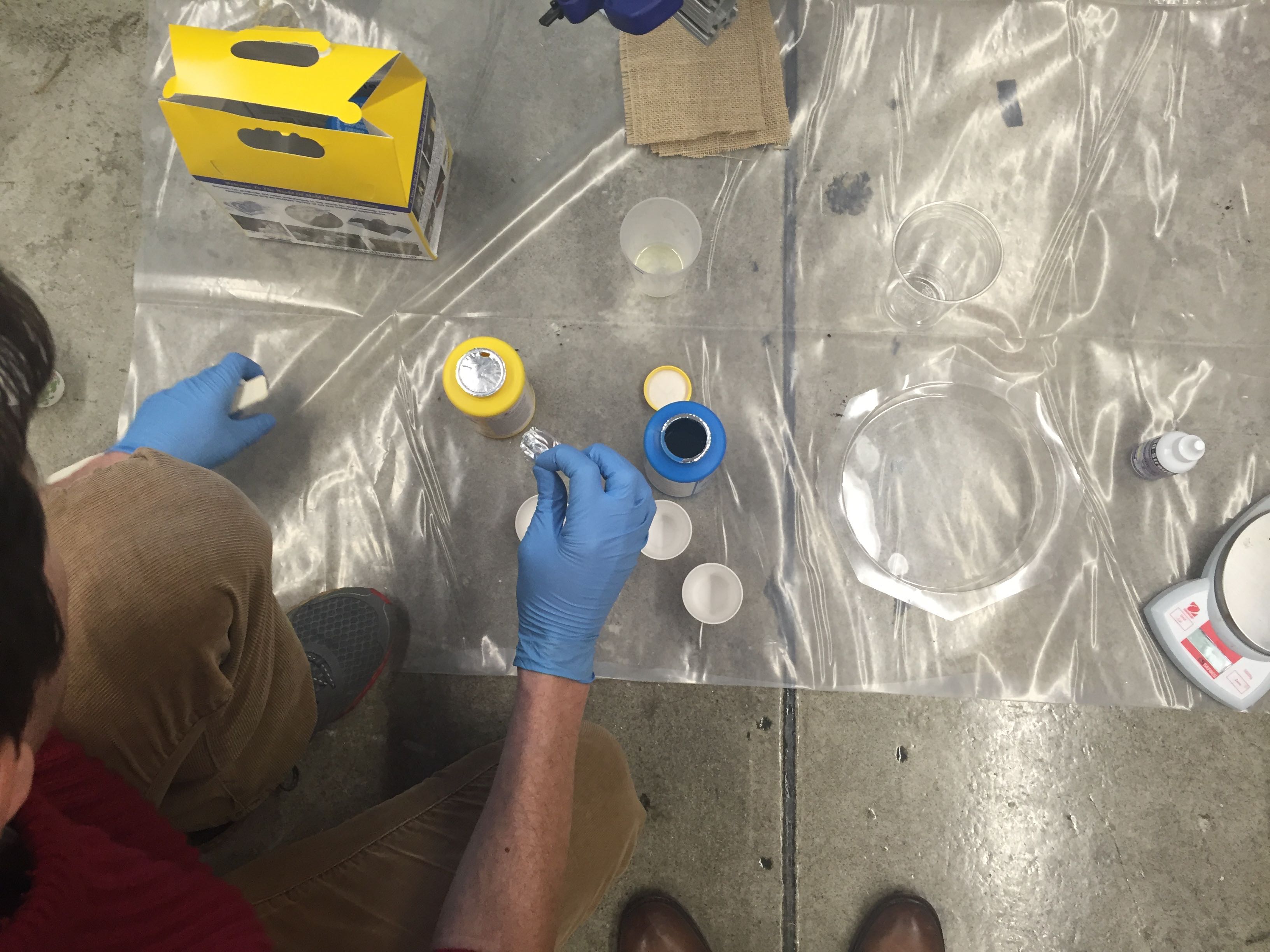
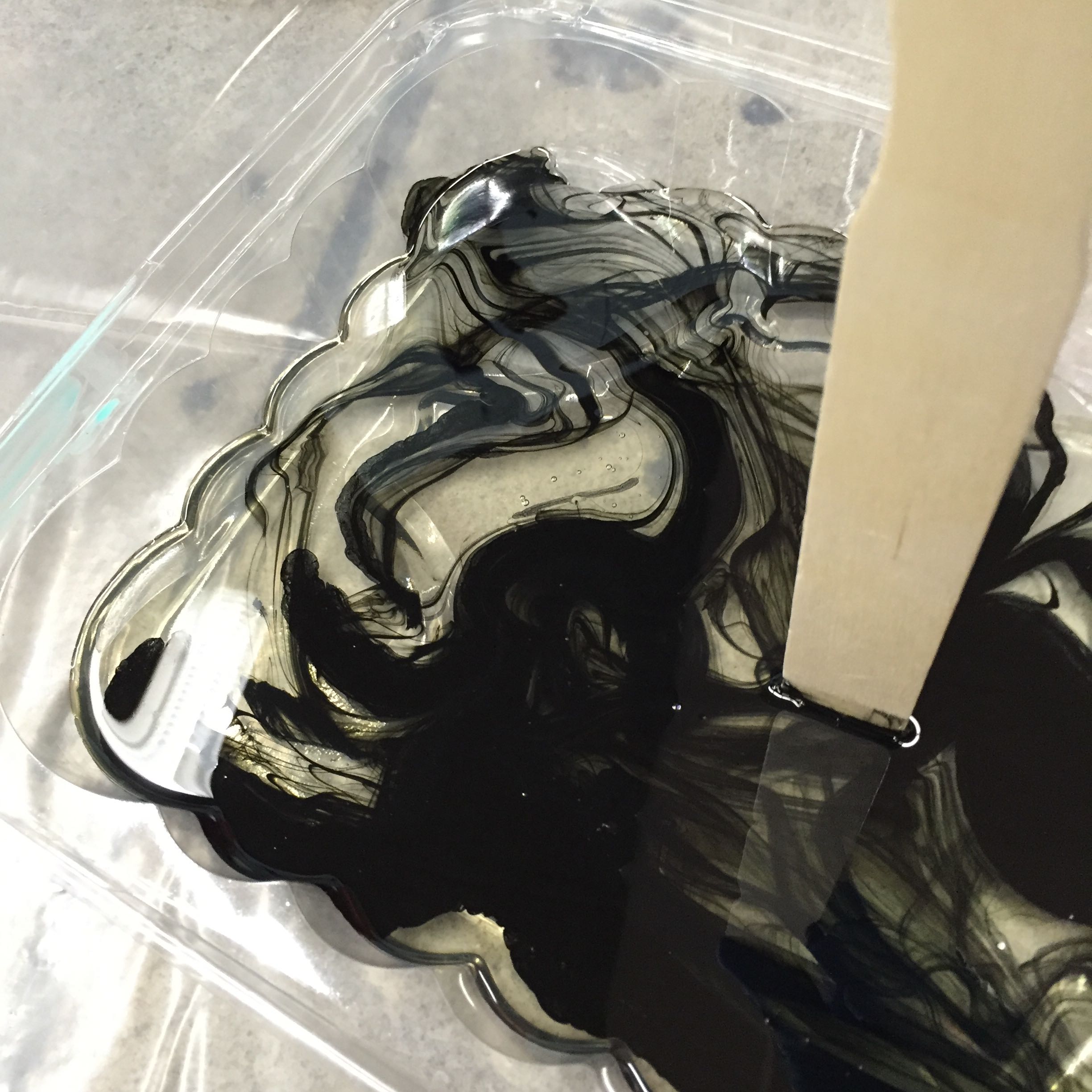
Beautiful special dye used to achieve final gray foam. Bit expensive at $15, but I was too scared to use food coloring and risk the whole thing not working.
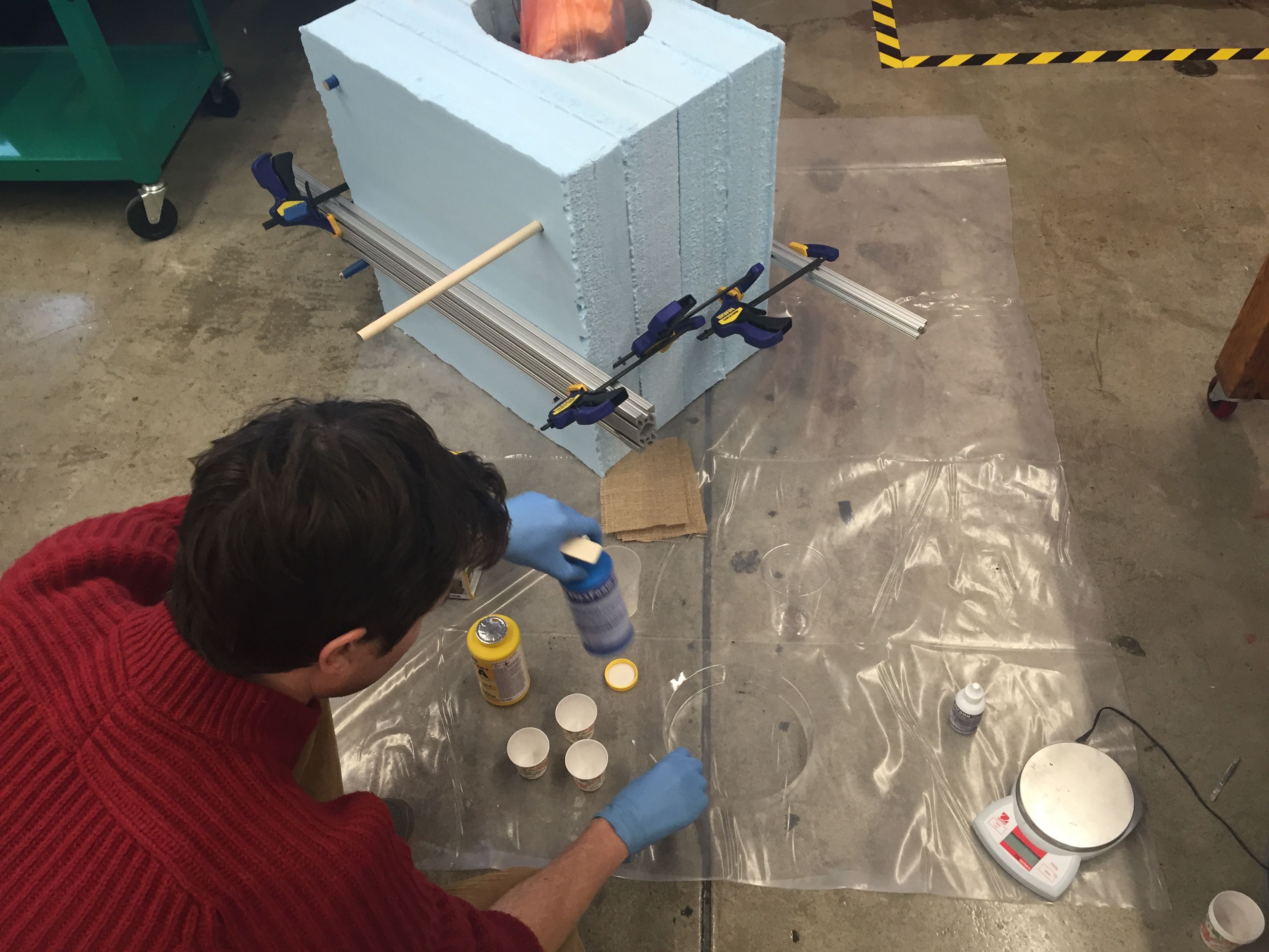
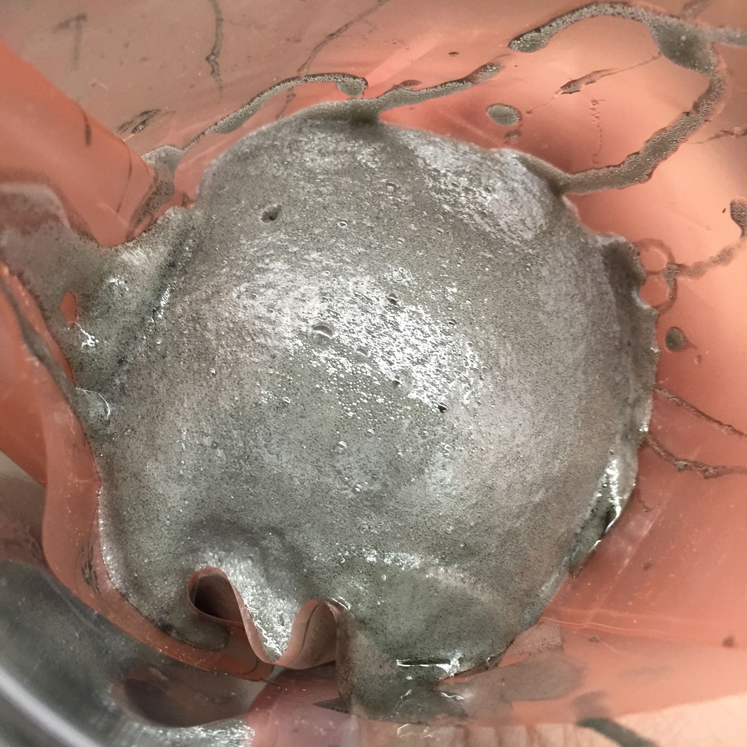
Test case- small cupful of expanding foam with nonstick 'compositing plastic'.
Since this came out well, it was time for full-scale approach! Scary moment!
Once the cast became tacky-dry (maybe 40 minutes), we realized that the wax coating was not truly enough to easily remove the mold... So we went through a short phase of clawing at the exterior before we devised a way to compress the sides to delaminate the wall-sticking problem.
Some hands for scale.
Showing some underlay that will eventally contain the piezo element and board.
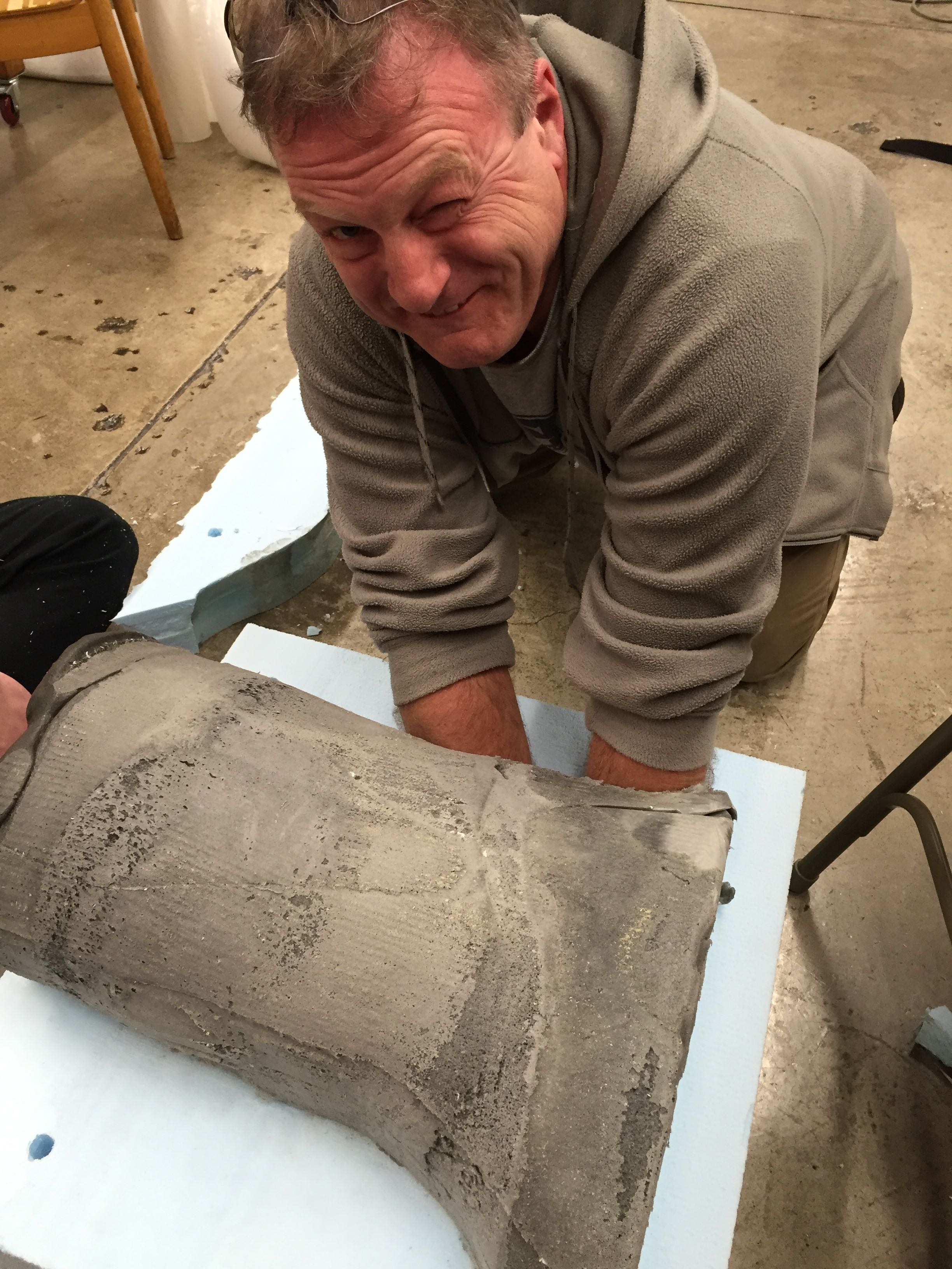
Delaminating edges with the reach-through technique.
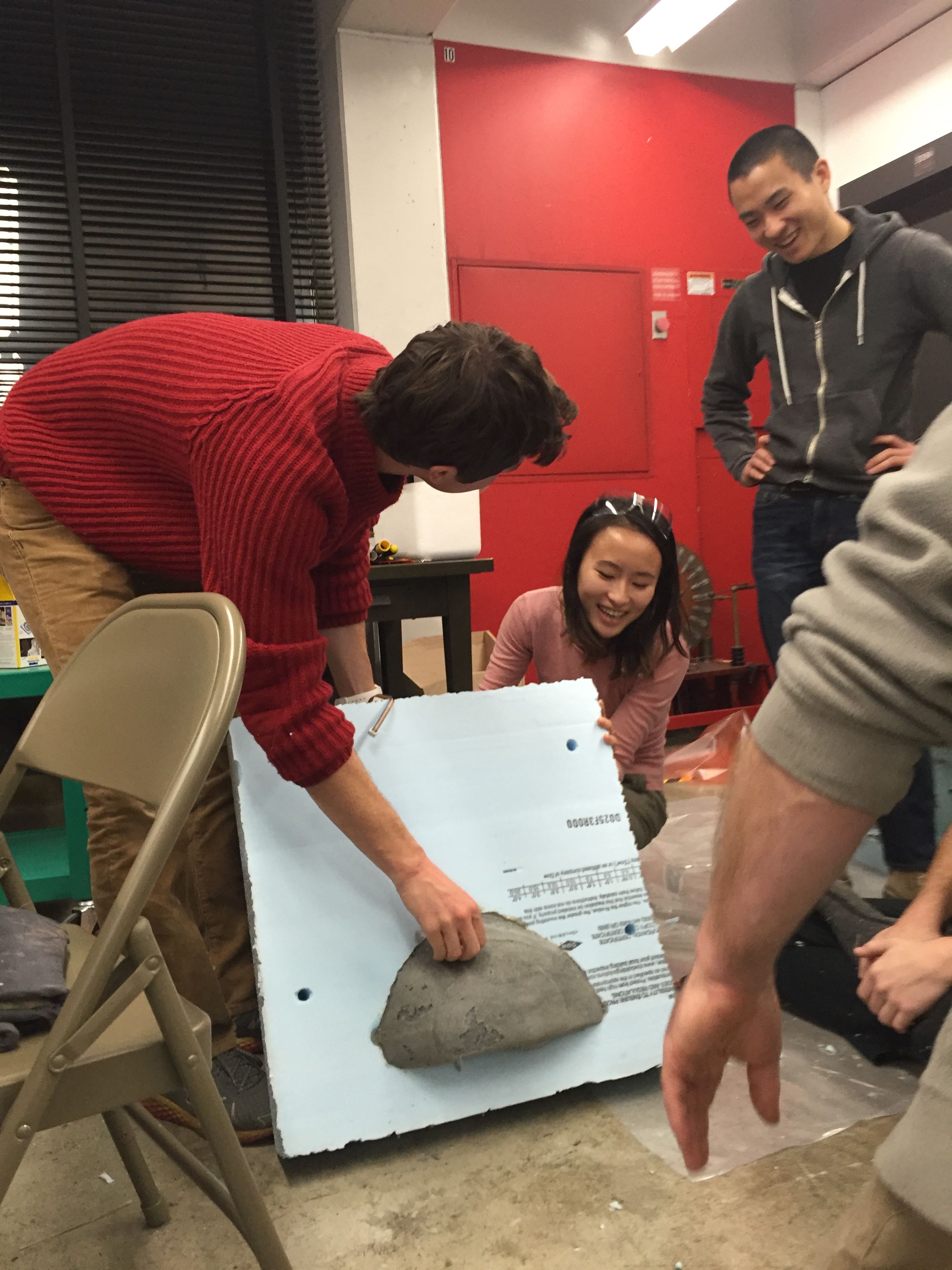
Front toes are free from the mold!
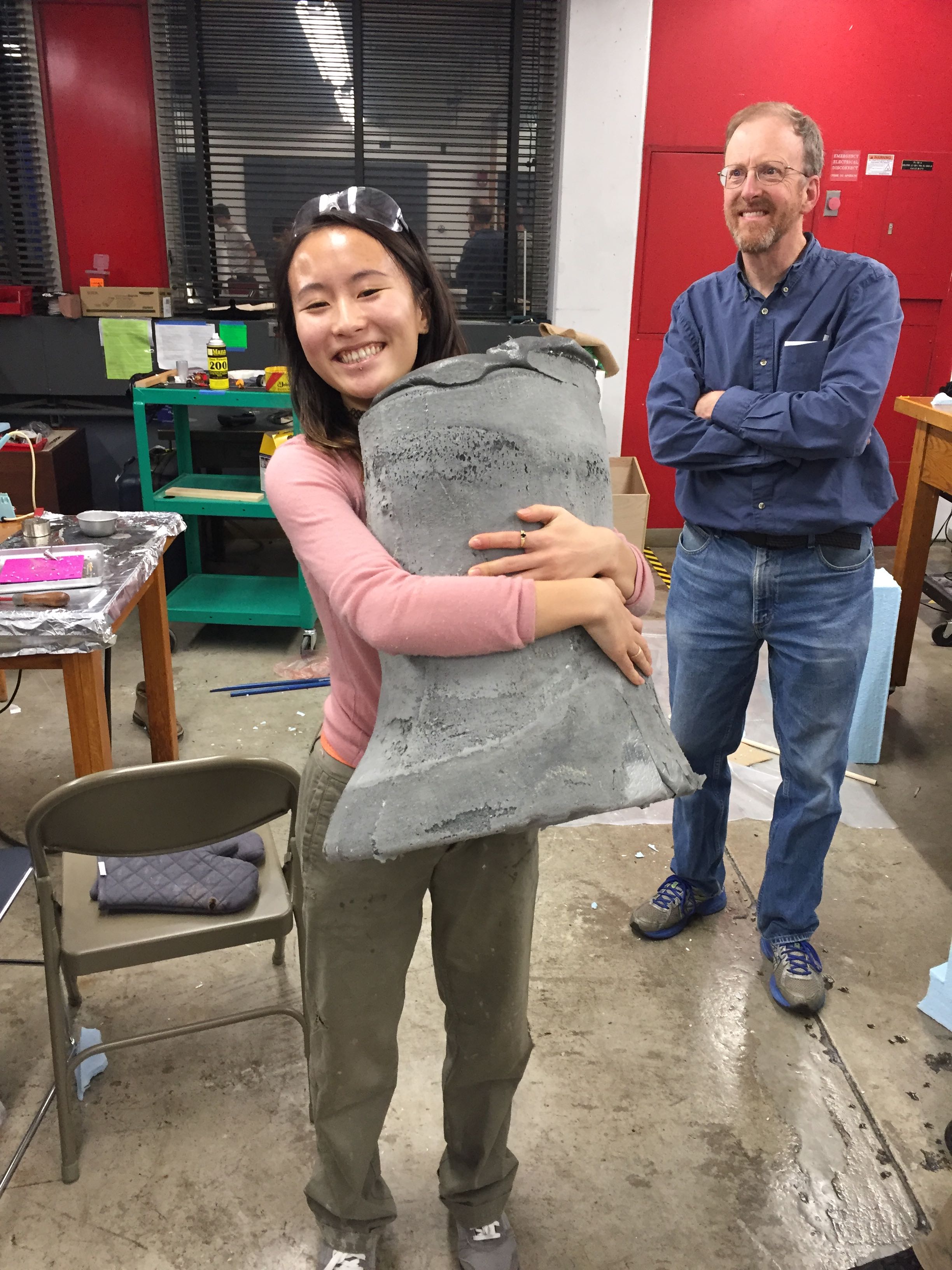
Hugging!
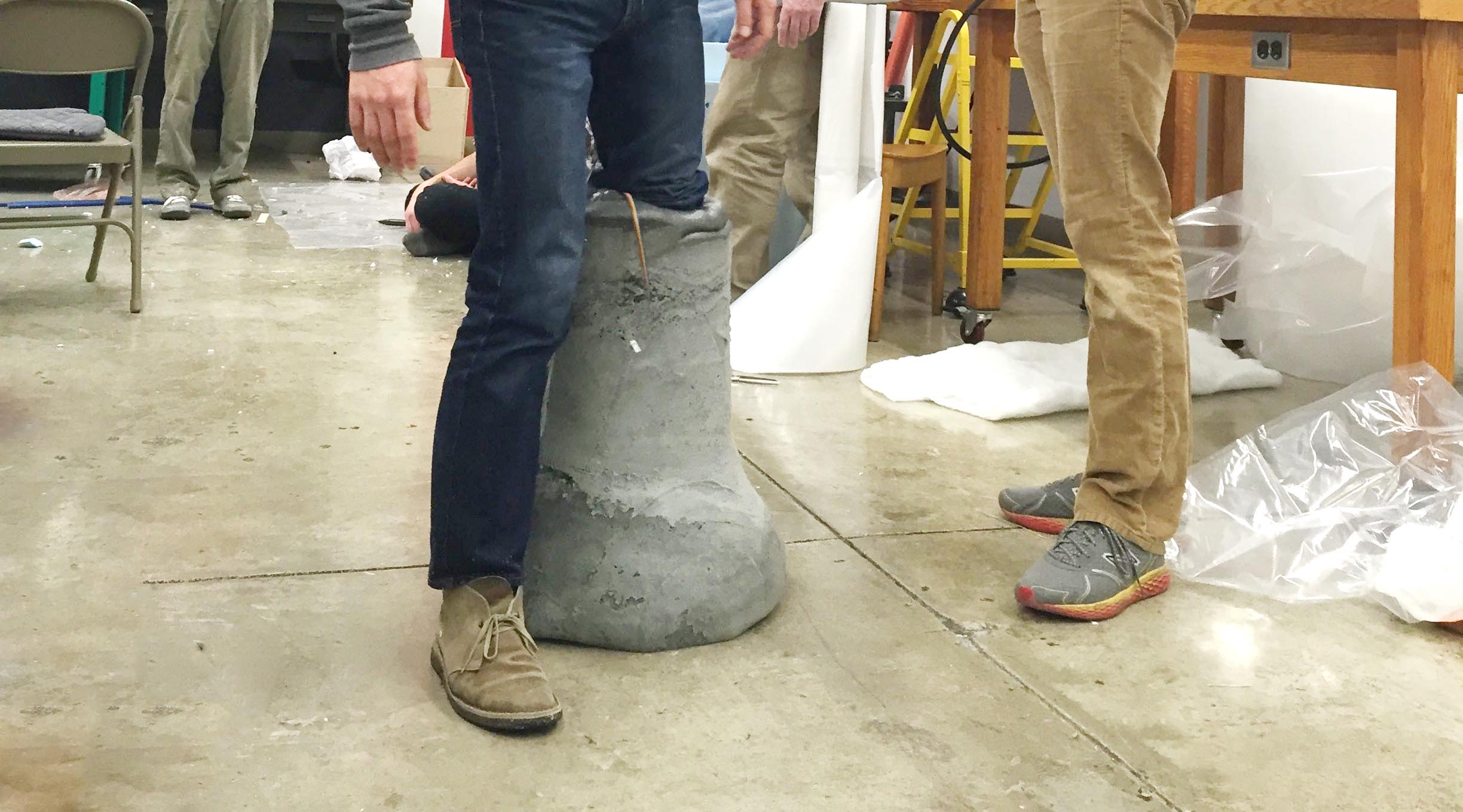
Wearing!
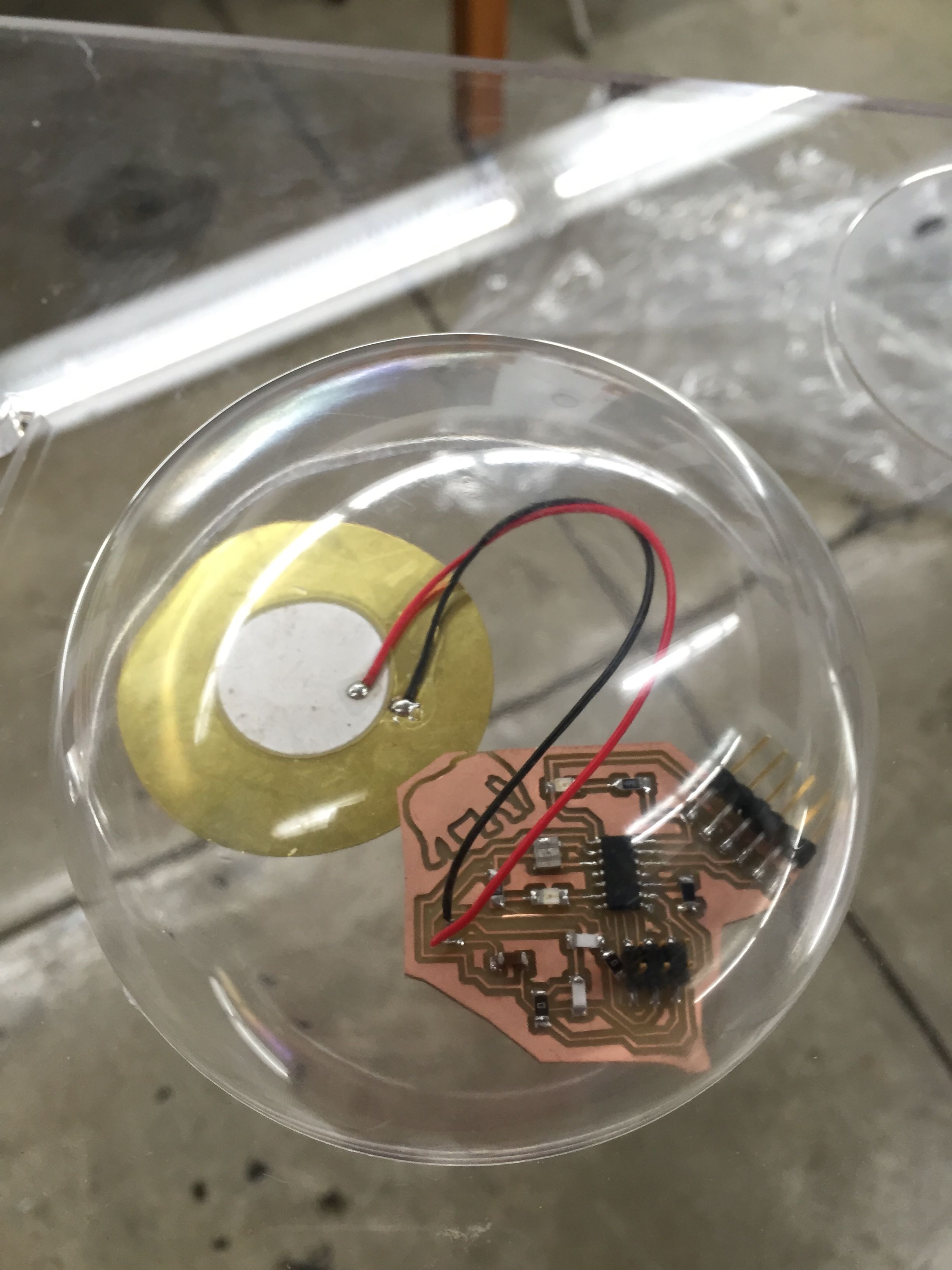
A final stage of construction was the piezo detector housing beneath the foot.
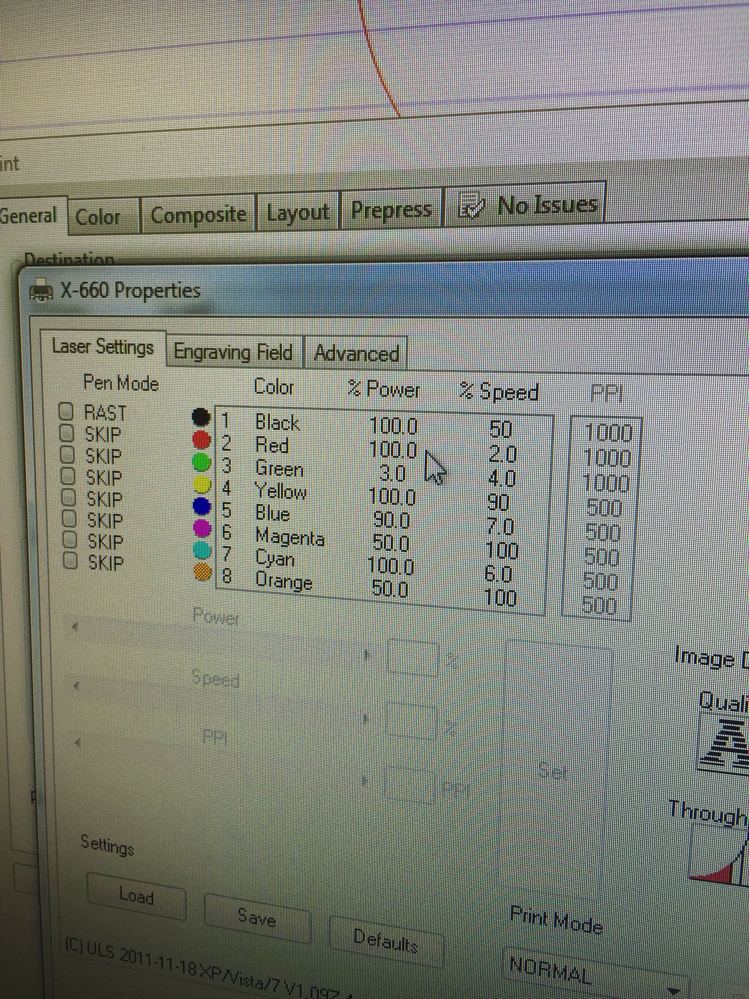
Raster etching something special for the cover.
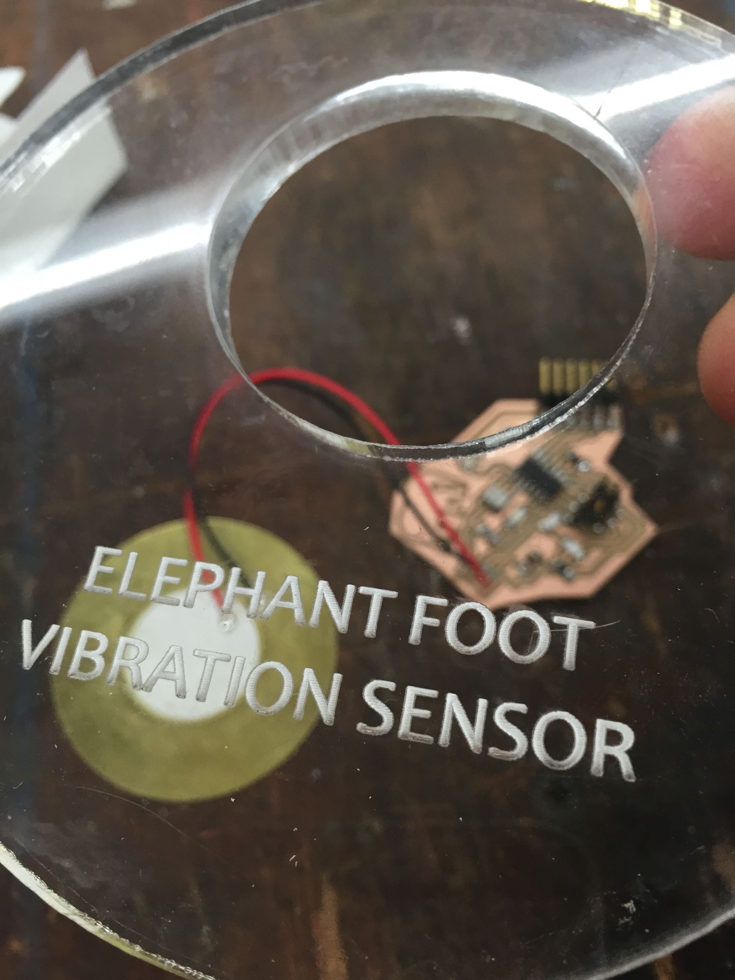
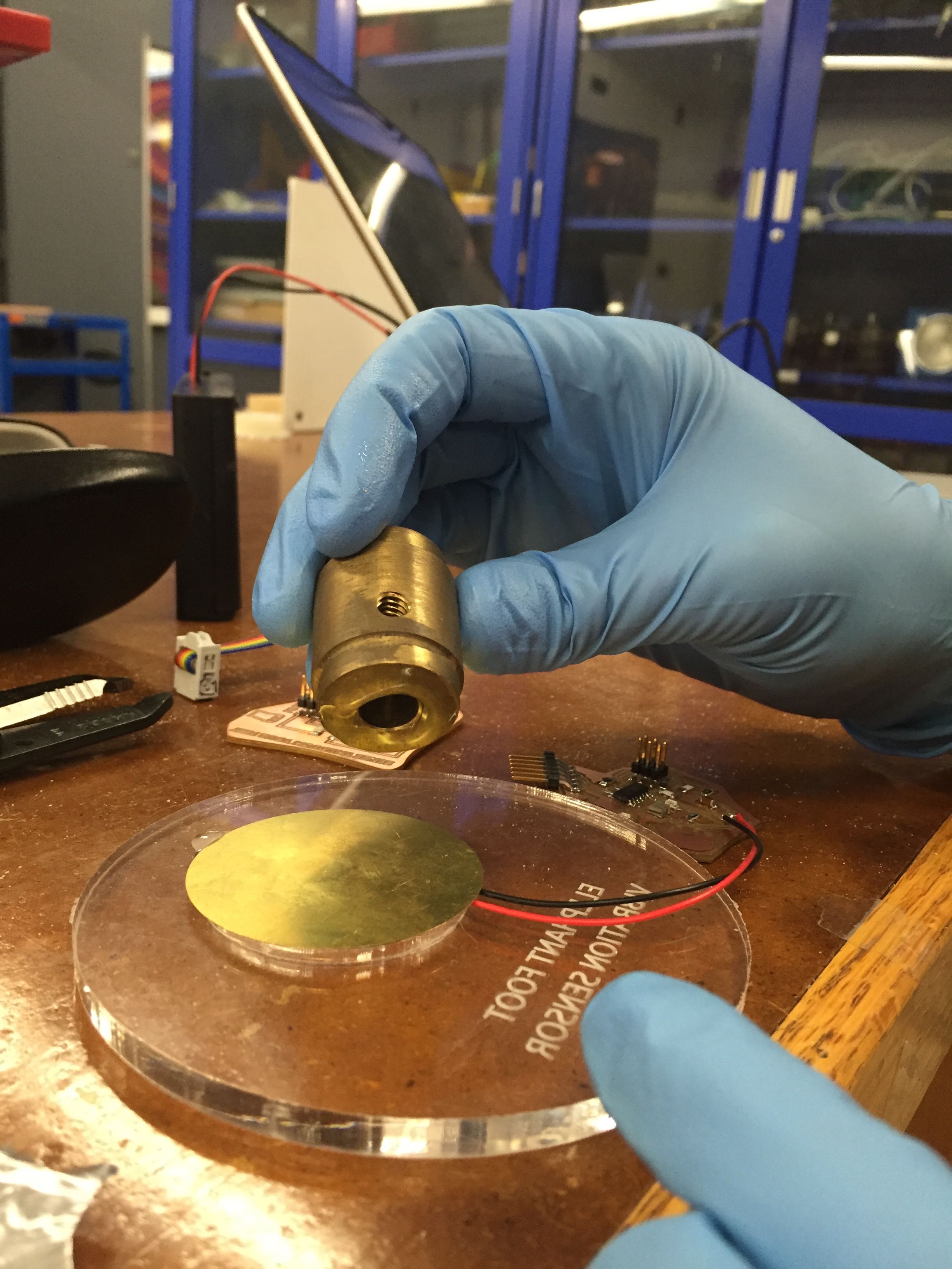
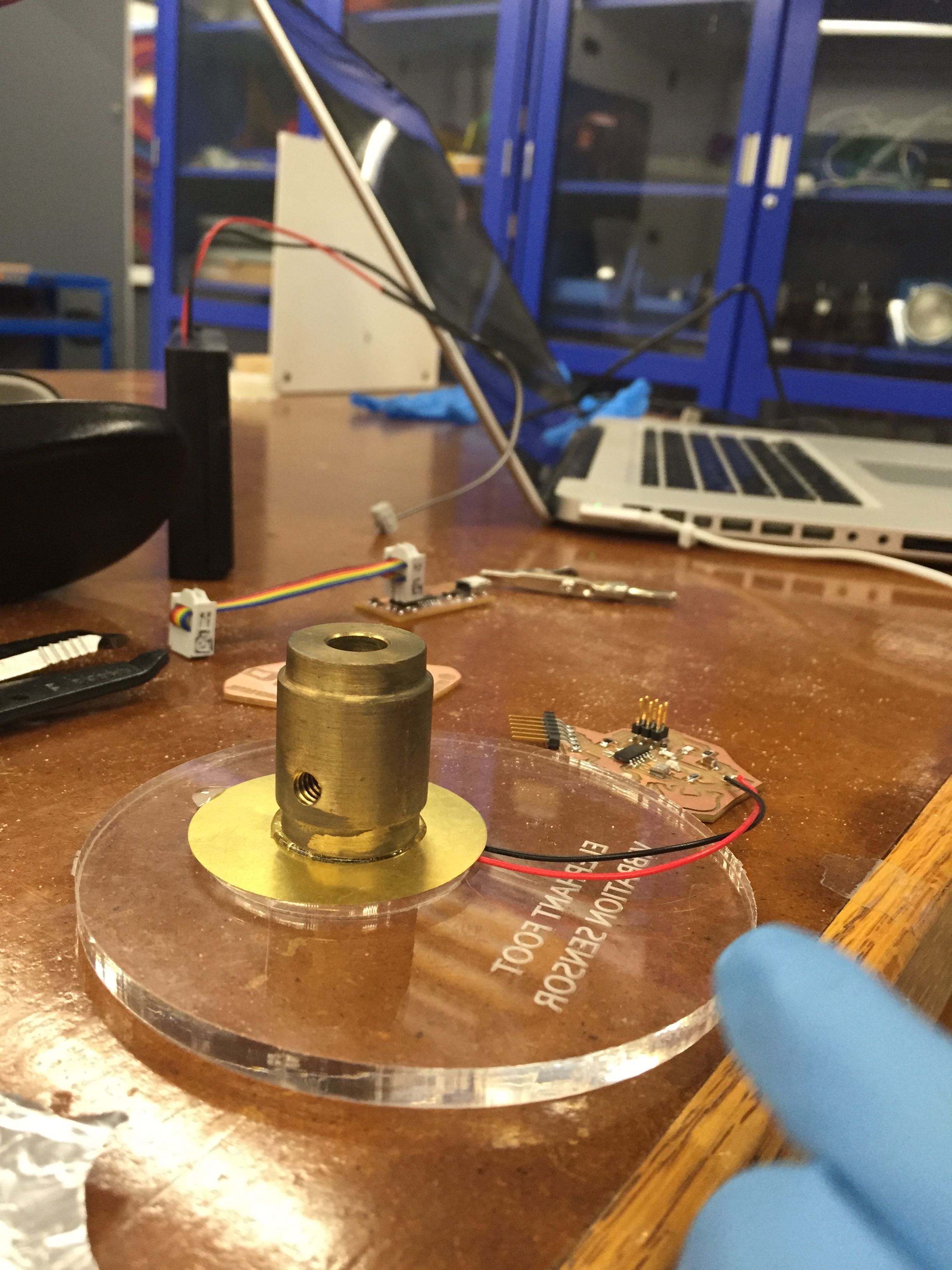
Affixing a weight to the middle of the piezo element. Much like a person standing on a trampoline, this will help give greater amplitude responses (increased sensor sensitivity).
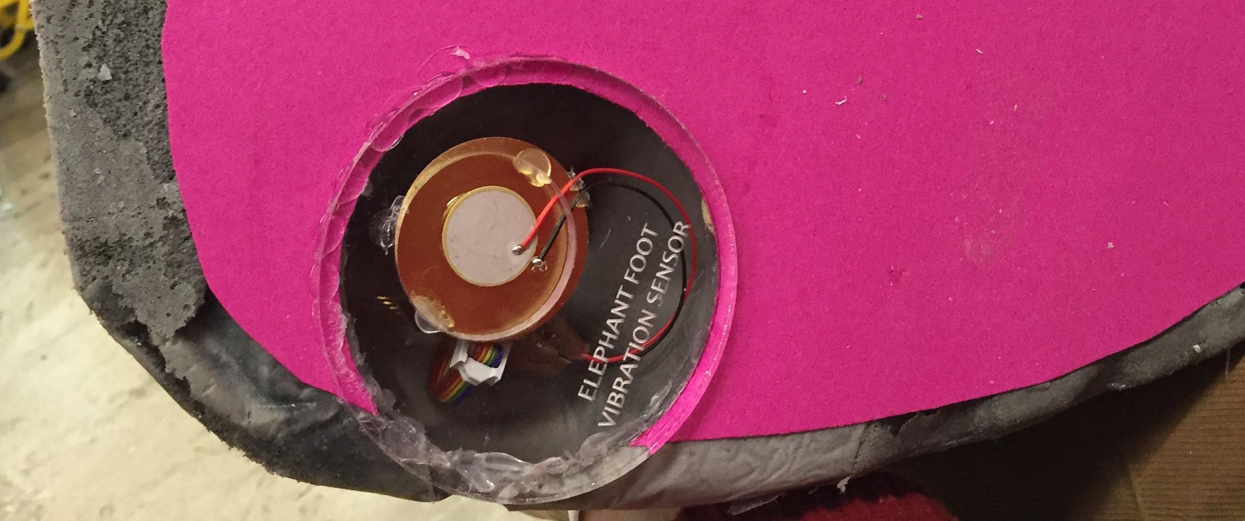
The sensor on the bottom of the feet!
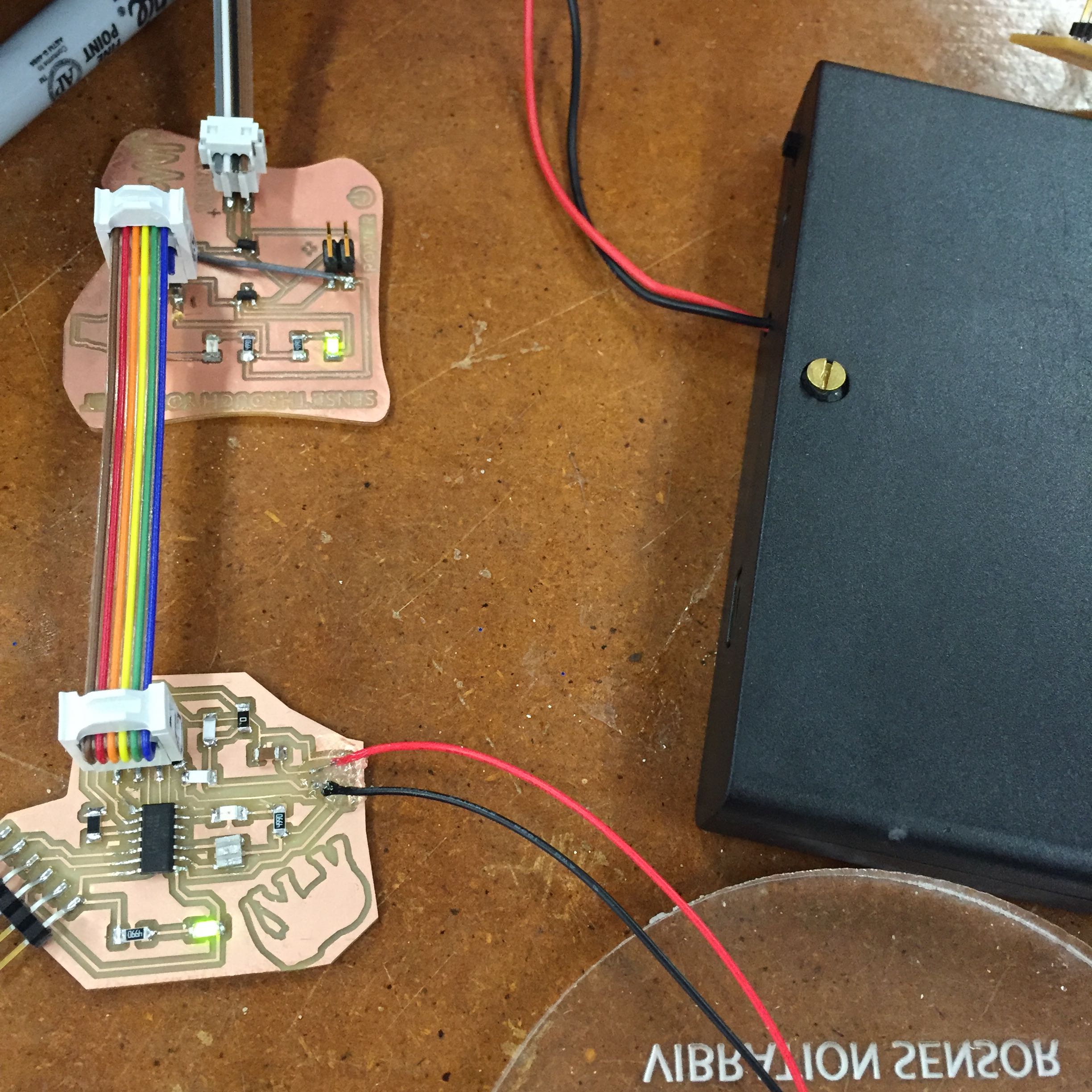
Closeup of the breakout board...
Final (First) Draft
Exciting!
The final color and texture are very believable...

The final flyer... people were happy and expressed a lot of enthusiasm and excitement about the project. Thanks to everyone who came to say hello!