Final Project: DIY EEG
EEG: Cheap and Small
Fall 2015
Why would you be interested in EEG? Not only because you can use your brain waves to make helicopters fly, or to write without moving a muscle, but it has real clinical usage: recently, the FDA passed an objective diagnostic assessment for ADHD using EEG.
While a commercial EEG set up can cost from around $100 to well over $30,000 dollars (depending on whether the set up is analog or digital, how many electrodes you want signal from on your head, and how clinical-grade your analytical/interpretative software is) and it typically requires a special carrying case that is often bigger than a suitcase. Complicating matters further, although there are multiple online guides describing how you can build your own EEG, most of the instructions are confusing or incomplete or both. I realized that if I could make my own and document the results, I would be doing future brainhackers a great service. Specifically, I wondered if I could do a set up small enough that I could put everything in my backpack and only spend $75 on parts. So, my project crystallized into a three-part constrained challenge: could I build an EEG set up that cost less than $75, that fit in a size smaller than a suitcase, and that would be easy for a newbie to configure (ie minimal components -- ideally less than 15)? My dream is to create an EEG system for electronics newbies that has somewhat differentiated hardware, software, and neuroscience modules. Here, we'll be focused on the hardware elements primarily. The verdict?
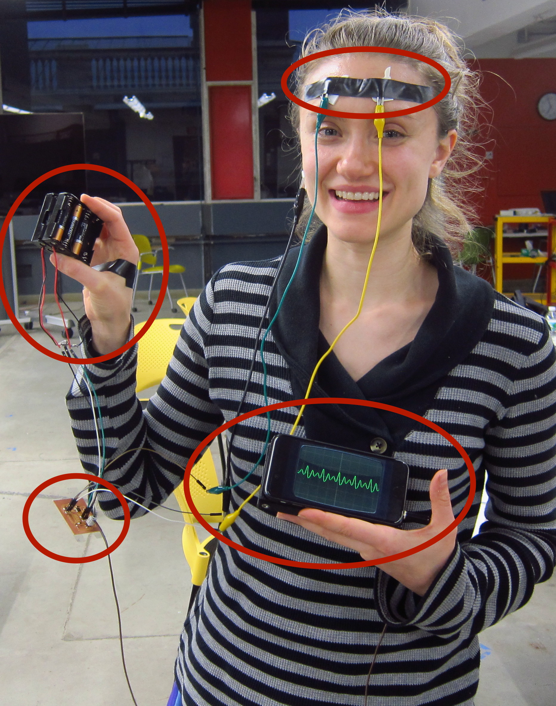
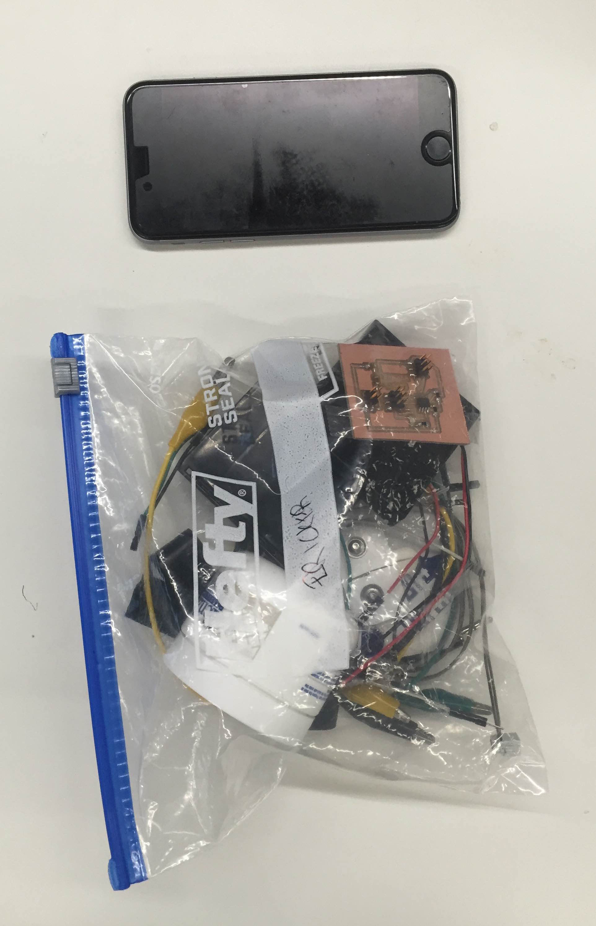
Here I am, showing off in true frizzy headed form: Here's the little ziplock bag of wonders:

Result: a quart size ziplock bag full of EEG parts and a smart phone is all you need. Total cost of parts: much less than my $75 target.
Parts list: although I used parts from the lab (with only two exceptions), I've given prices below in case you don't have these materials on hand.
Total time: approximately 20 hours of labor. That was because I was figuring it out as I went, though! And making lots of foolish mistakes. Lots. But fear not, good reader: with these EAGLE files and my detailed parts list, you will be able to do it in a fraction of the time I spent.
PARTS LIST (I've ** the two things I bought specifically for the project): soldering iron, roland mill, etc (sunk cost) laptop (sunk cost) free visualization sw (Audacity, Garage Band, Physics Oscilloscope) **two 4.5v batteries (I got 1.5v*3*2) = $5 ** led (if green or red, use a 1k resistor, if blue use a 499k resistor -- I chose to use green) = $0.15 1k resistor (for led; can be from 1-10k) = $0.01 1k resistor (for ad620 - for gain) = $0.01 **1 AD620 chip (instrumentation amplifier) ~$11 ** 4.7k uF capacitor (in this case, I just used two 10k uF in series) = 2 x 0.10 2x3 header (to connect the electrodes) = ~$0.7 2x2 header (to connect mini stereo plug) = ~$0.7 3 disposable electrodes $8 alligator clips bunch $3 Battery case ($1.10 x 2) = $2.20 mini stereo plug ($2.30) conductive paste $20 in bulk, but I got free at a conference jumper wires (male-female, female-female) $6 for a set electrical tape $2 double-sided tape (to hold down board while milling and soldering) $2.30
Notes on why the circuit is constructed the way that it is and why:
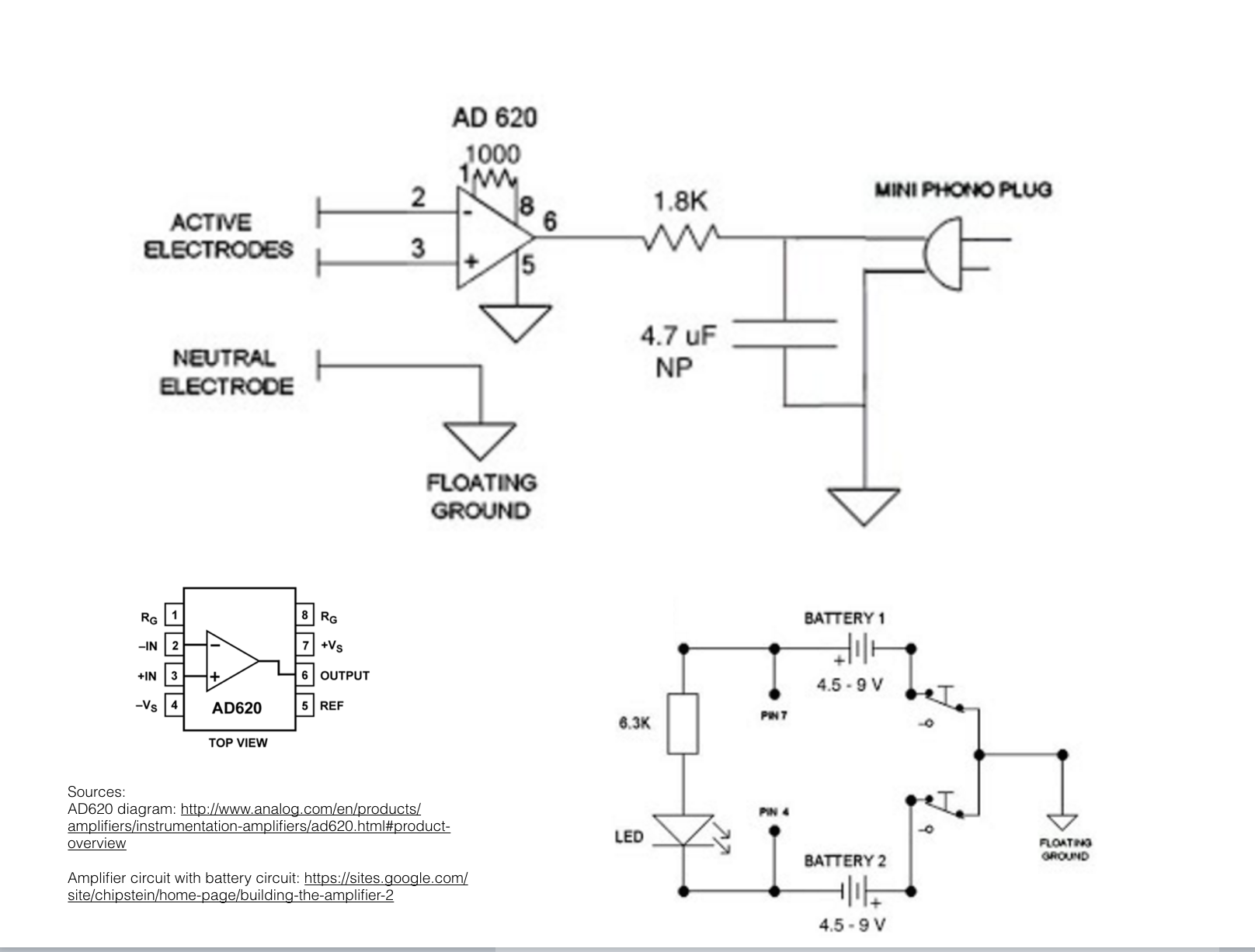
In the picture I've shown above, the two active electrodes are on my forehead and the neutral or reference is on my ear lobe. The signals get sent through the electrode and the attached wires into the circuit dangling below. That circuit is responsible for performing two actions: amplifying the tiny signal and filtering out some ambient electrical noise (typically 60 hz in electrified environments). A mini-stereo plug is where those modified signals get sent out of the circuit and into my phone. On my phone, you can see the signals have been processed by the circuit and are now being visualized in an app called Physics Oscilloscope. The batteries I'm holding are powering the circuit (so it could do the amplification and filtering). A few more specifics: the RC filter here is supposed to be about 200 hz which is why we use a 5uF capacitor (well, to be precise, two 10k uF caps in series) and a 2k ohm resistor after the signal comes through the in-amp. Also, the 1k ohm resistor on the ad620 establishes sufficient gain (over 50). The battery set up looks a bit bizarre - two battery packs with three 1.5v batteries in each one so that you have the equivalent of 4.5v coming in through each. Apparently that is a safety (and possibly an efficiency measure), but if you want more detail, check out the notes on Chipstein's description of building the amplifier.
My circuit is an adaptation of the circuit provided by Chip Epstein. His schematics are more conceptual than fully schematic and his board is a breadboard, but the idea of it was of course very transferrable. 
Note that the AD620 instrumentation amplifier is critical to use for amplification process. It is often said, but it bears repeating: EEG signals are small (10-20 millivolts)
For a moment, it seemed like I'd created a microphone just with the wires. However, when I turned off the mic input, the signal vanished, not surprisingly.
OTHER CONSIDERATIONS
Initially, I'd planned on using a homemade version of the Arduino. However, after asking Chip Epstein whether he'd update anything on his site if he had to go back and do it again, he volunteered this: "The main weakness of the original circuit is the use of the Arduino or anything else based on the atMega, because its A/D conversion is very noisy."
As mentioned during the input/output week projects, I considered adapting the Fab mic board and stereo board (for sound as well as visual output) and using the attiny45 microcontroller on that board to do, among other things, analog to digital conversion and to take care of some additional amplification. For more on those details, please check out the Output and Input week pages. In the future, as I built out the software module for this project, I may incorporate that as an alternative hardware approach.
'For visualizations, I debated using the oscilloscope code described in the Output week assignment. However, before I got to that part of the spiral, I wanted to check that I would get any output.
On my laptop, I used Audacity (downloaded from internet) and Garage Band (Mac specific). On the phone, I used an app called Physics Oscilloscope.
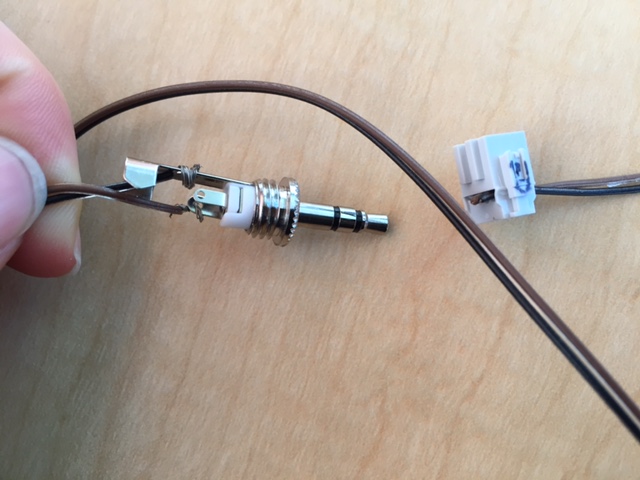
One major issue is that both the phone and the laptop have mics on them. Because of this, it is possible that programs like Audacity and Physics Oscilloscope actually pick up additional speech. For instance, when I configured the mini stereo input by twisting and soldering two wires to a mini stereo port.
Here are my EAGLE files: ERicker_EAGLE_EEG_Files_12.14.15.zip
Primary source of my EEG set up was one that I found online (although I consulted many, many, many more in addition to his): Chip Epstein's site: Chipstein's Homebrew Do-it-yourself EEG, EKG, and EMG
Other EEG sites that I studied but decided not to incorporate designs from for various reasons (although I appreciated seeing the different approaches they took to amplifying and filtering the signal -- few things help you understand the essentials of a process better than seeing multiple and very different approaches that still manage to render the same output): Open EEG, Open EEG, Open EEG, DIY EEG Instructables. Also, a site describing a simple ECG board that provided some great inspiration was actually written by former How to Make (almost) Anything students Adam Marblestone and Charles Facchia.
Recap on why not other designs for the circuit: instructables (too many components: 3 chips, 11 caps, 16 resistors, 2x9v batts, a breadboard); ECG fab from Charles Facchia and Adam Marblestone - not EEG; open eeg - not enough detail; mic + stereo — too many components and uncertainty around which parts to use: considered only attiny45 but realized it wouldn’t handle the multiple active leads but it needs to go through two otherwise you don’t really get it.
Another issue was that the LED never got hot and did not go on; it was connected to positive charge on one side and a resistor on the other side, but it should probably have been better grounded. I tested other options for whether or not the signal was validly biologically derived or a lot was coming from the microphone. It was hard to tell, because by the time I realized that the microphone could have been contributing significantly to the big glorious looking signal, I also had a hardware issue that could have eliminated the signal, too (the LED shorted due to a mistake during testing with the multimeter). The things I checked out when assessing the hardware issue: Electrodes (multiple types, without and without electrode paste, multiple locations, without and without electrical tape), traces and solder (multimeter - part of the problem), wires (multiple types of jumpers and other connections - always going for smaller, lighter, easier to use, which meant eliminating the long loopy wires I started with), Batteries (tested individual batteries, tried connecting battery ground or just using floating ground from the electrode), different software visualizers (Audacity, Oscillo on iPhone, Garage Band), different connectors (2x3 and 2x2 header enclosures versus single enclosure connectors). The goal was to identify whether there was something other than hardware so I wouldn't have to redo the board and potentially create another error.
Additional steps for the future
incorporating 3d printing and building toward the portable, printable, personal brain lab (incorporate with harry and also 3d print my own mri of brain)