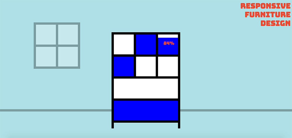
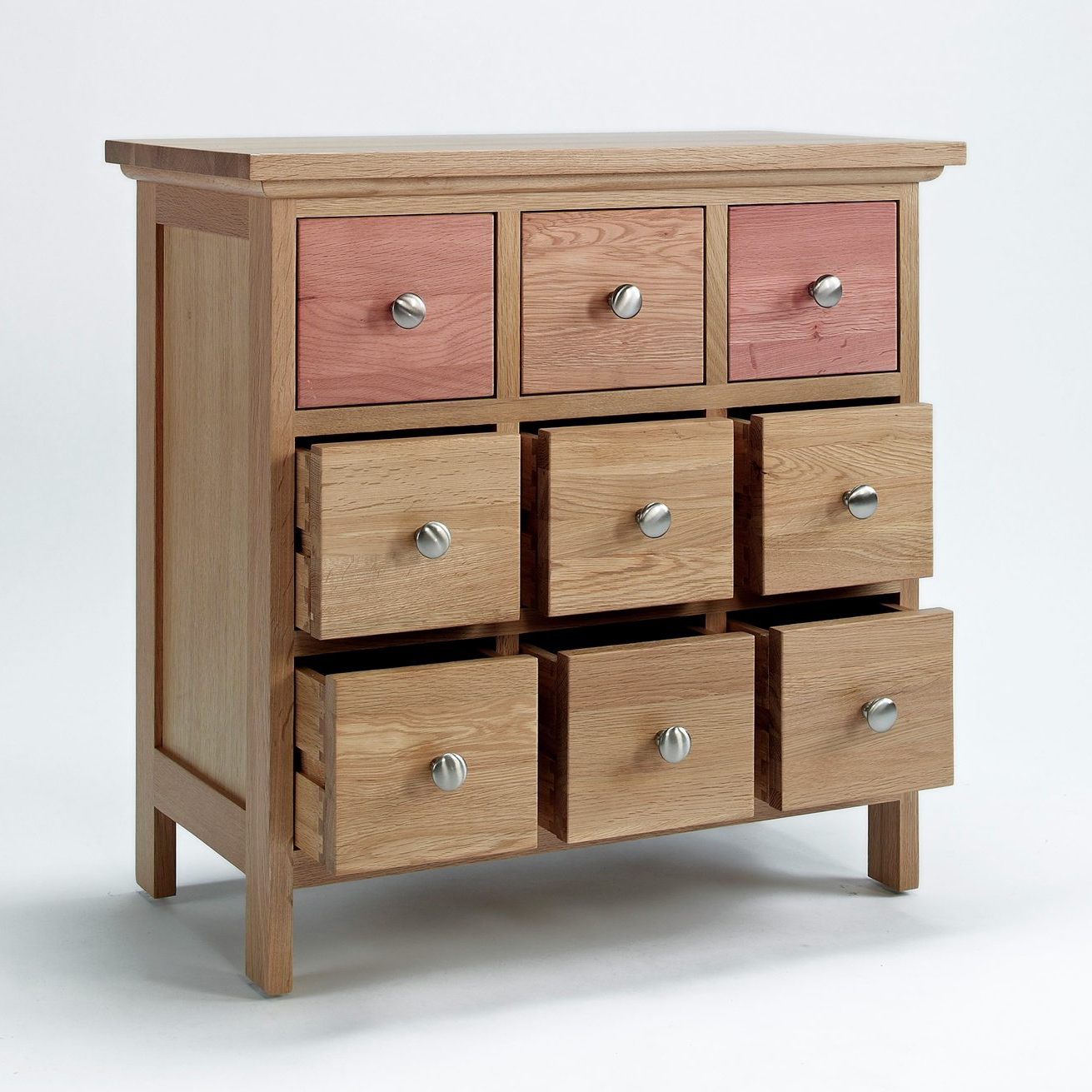
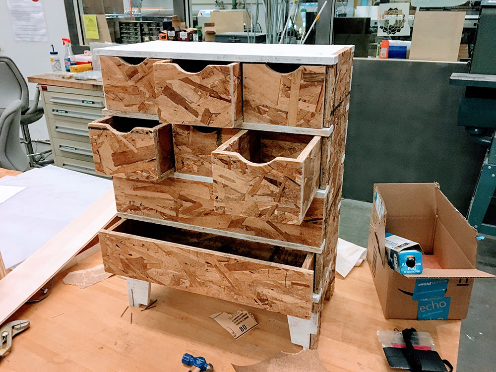
The smart chest of drawers changes design depending on its contents. Each drawer has a distance sensors that detects the amount of content inside. Depending on how full the drawers are, the front of the drawer will change color with thermochromic paint. The user will know which are the drawers that are full with just looking at the piece of furniture.
Responsive Furniture Design from Anna Fusté on Vimeo.
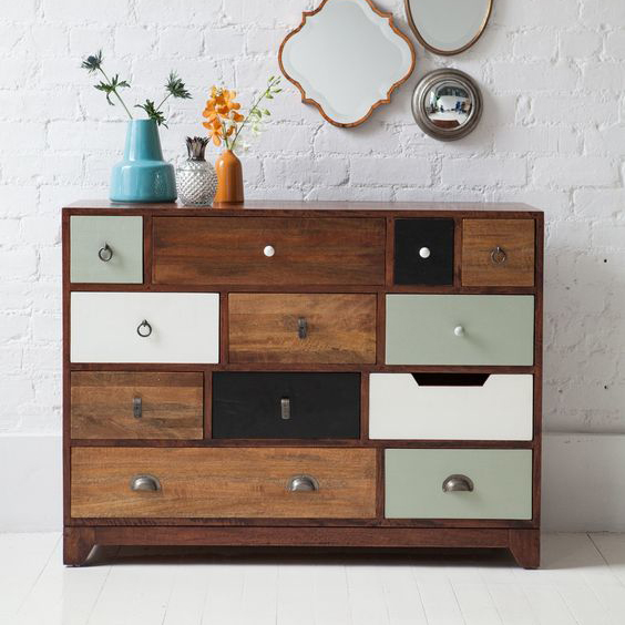
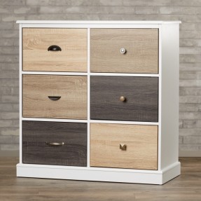
There has been a bunch of projects in the past relevant to what I made. Some of the ones that helped me and inspired me:
I designed the chest of drawers in Rhino. I also designed all the structure and the electronics inside. I designed the PCBs that control the drawers and the heat board to heat the front of the drawers.
The following parts were made from scratch:
This final assignment has been really useful for me in order to get a better knowledge in the areas that I am not very good at such as electronics and building. With this project I've been able to learn and improve a lot my electronics skills. The most interesting part has been the production of the heat boards where I've been testing with different values and thickness of the traces in order to get the proper settings.
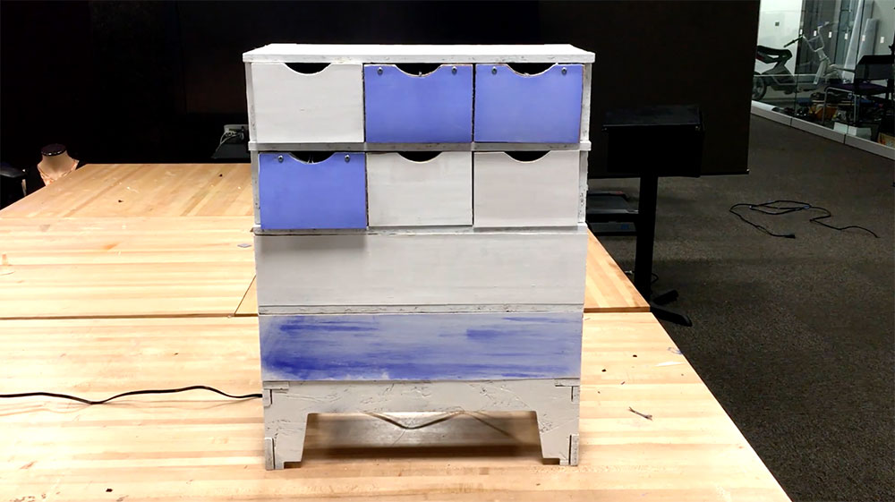
To evaluate the proper operation of the project, I filled the drawer with an object and observed the color of the drawer change from blue to white. I then removed the object and the drawer went from white to blue. I could also observe the value changing on the interface I designed.
The resposnive furniture design works as a good interface for any kind of furniture to have a visualization output of the state of the piece of furniture. The data represented with the thermochromic paint can be any kind of data from the piece of furniture. It can come from the state of the piece or from external environmental inputs such as temperature, humidity, sound, etc. It is a great tool for representing data with normal materials such as wood, in this case.
My final project is a smart chest of drawers that can change its design depending on the content of each drawer. The drawers will have sensors inside that will measure how empty they are. Outside, they will have heat boards and will be painted with thermocromic paint. Depending on the amount of content in the drawers, their color will change.
Inspiration:
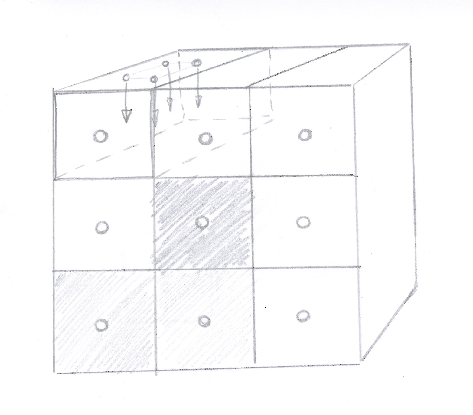
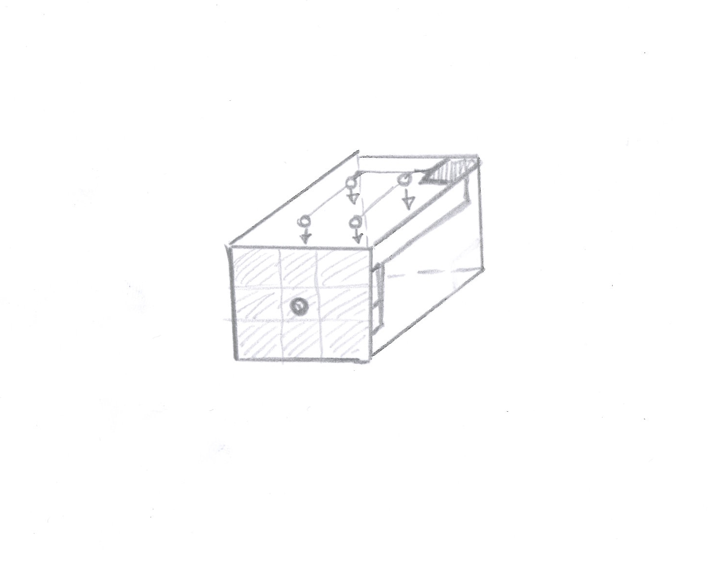
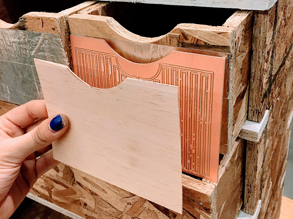
The idea is to use an array of sensors pointing downwards and tracking the amount of content on a drawer. The sensors send the value to a PCB that heats a board on the front part of the drawer. This front part of the drawer is painted in thermochromic paint that will respond to changes in temperature. When the board is heated the color will change to another one changing the design of the drawer.
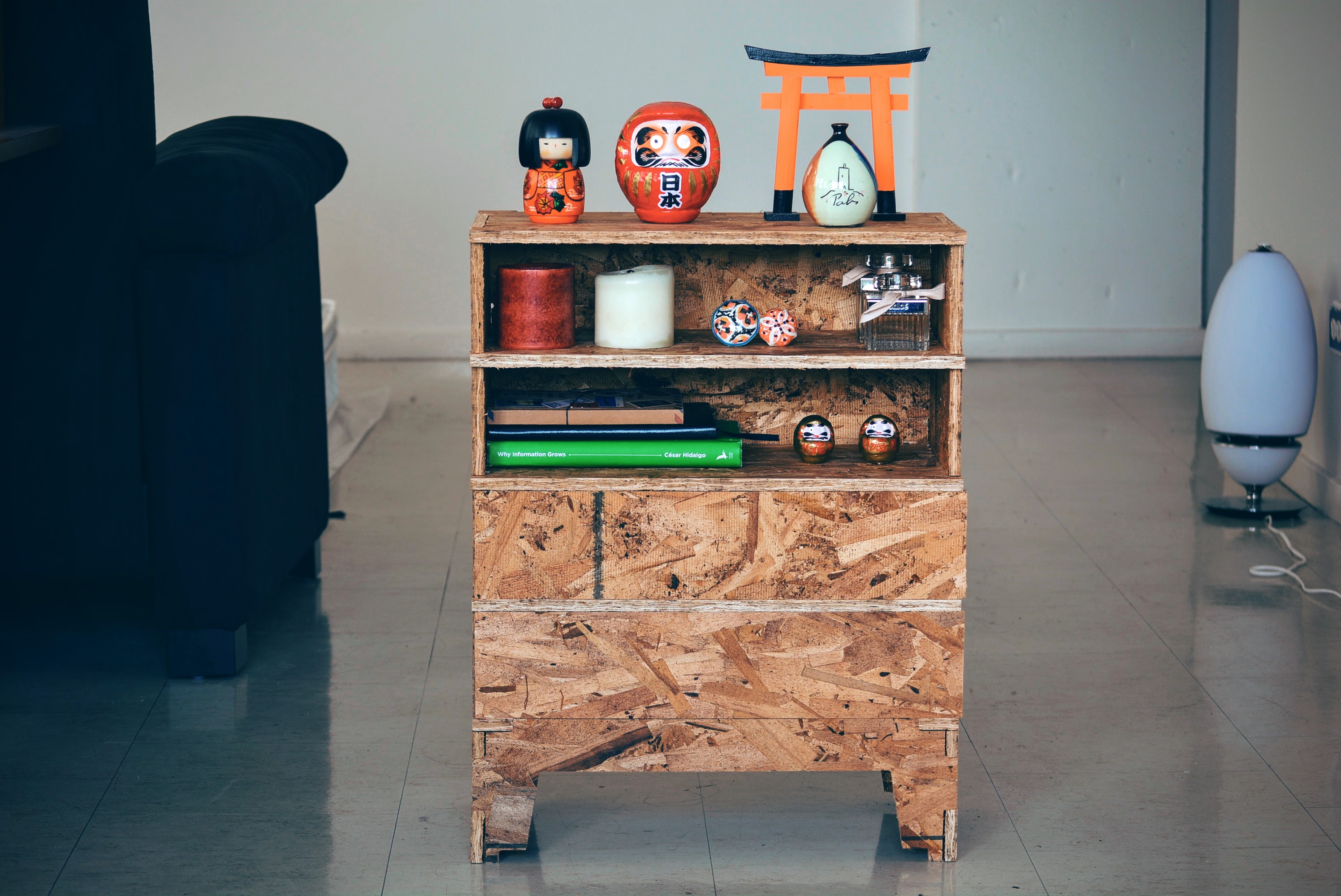
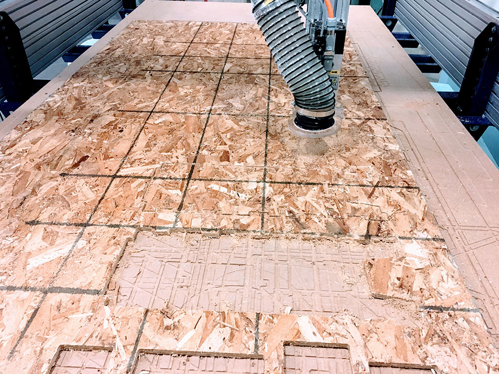
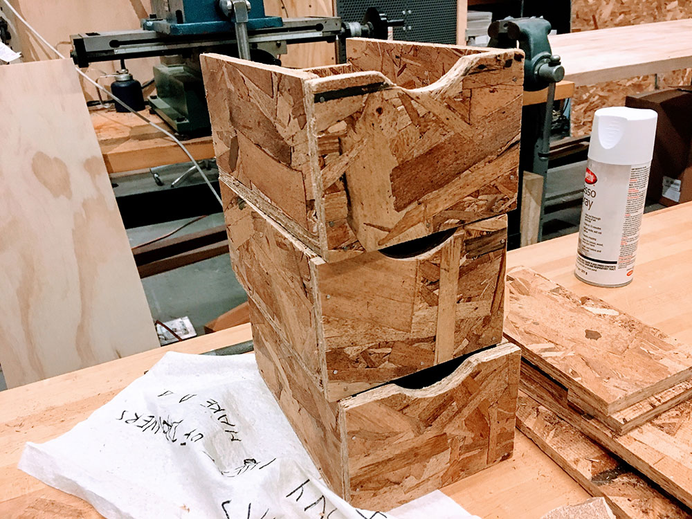
On week 5 I designed the chest of drawers and I used the Shop Bot to cut the wood. I used Rhino for the design.
To make the chest of drawers I used the OSB wood provided by the CBA machine shop.
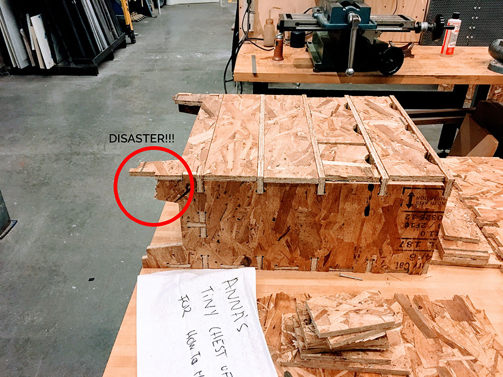
I had to cut the wood again as at some point when carrying the piece, it fell and some of the pieces of wood broke.
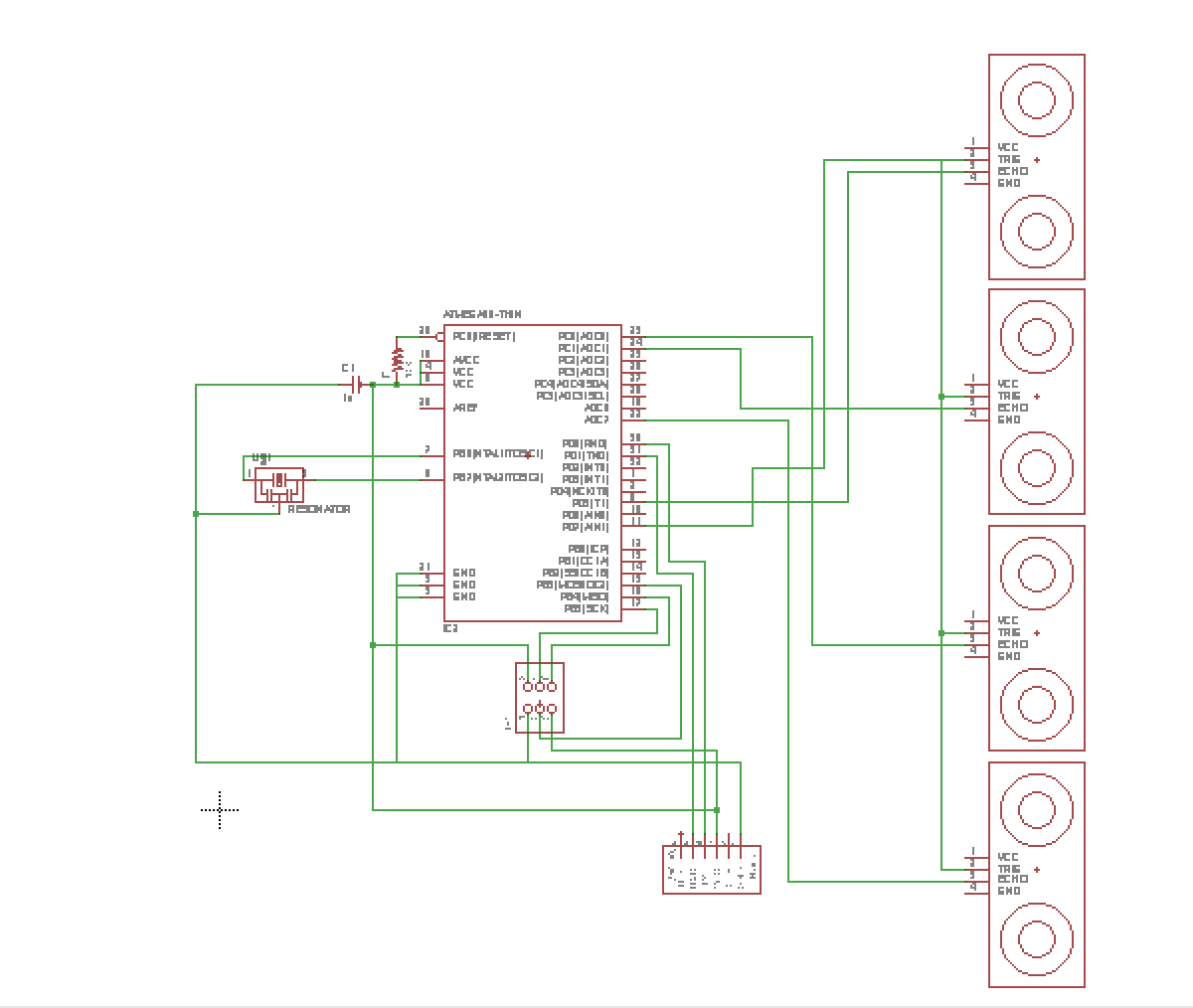
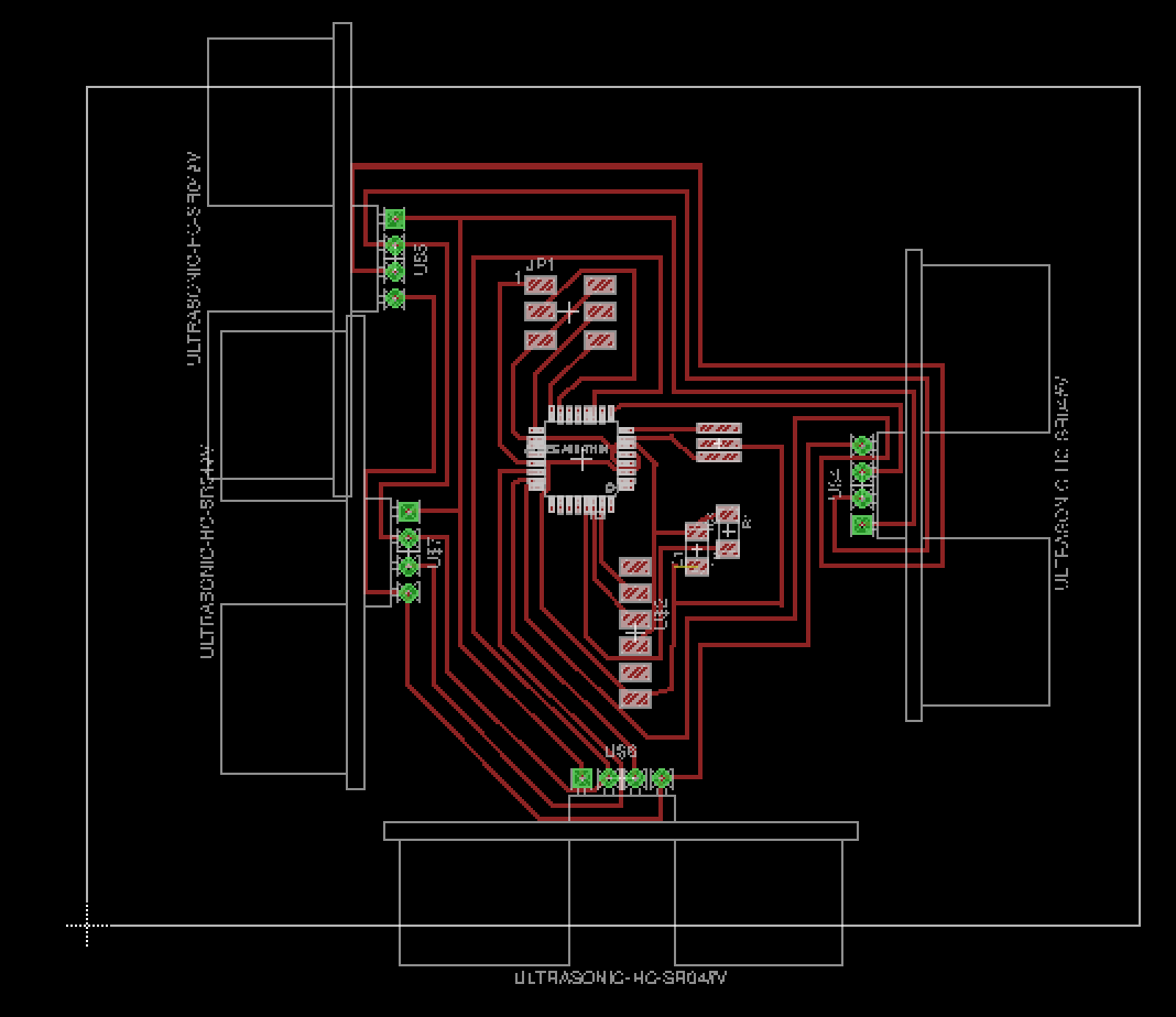
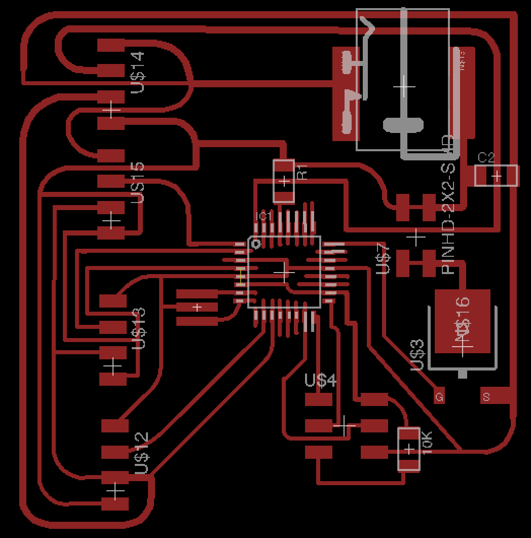
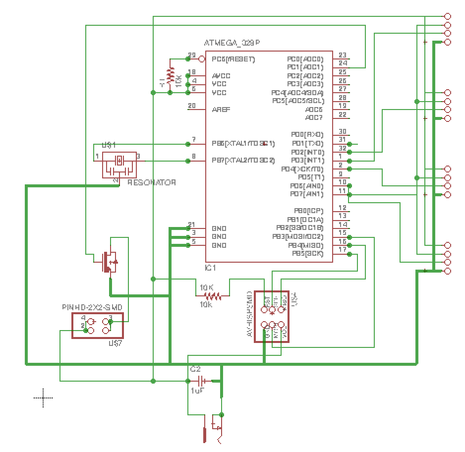
I have been working on the electronics for the interior sensors of the drawers. I will use 4 sensors per drawer connected to a microcontroller that will record data from the sensors when the drawer is closed. This is the first design I made (not the best design actually and not the one I will be using for the final version).
After realising this was not a very nice design, I decided to start from the very beginning and try to design a board with one sensor only and the heat board output. I started designing with a regulator. Ali helped me a lot understanding some basic electronics that I reviewed on week 10. I then realised I had designed on Eagle with the wrong regulator. So I changed it to the other model.
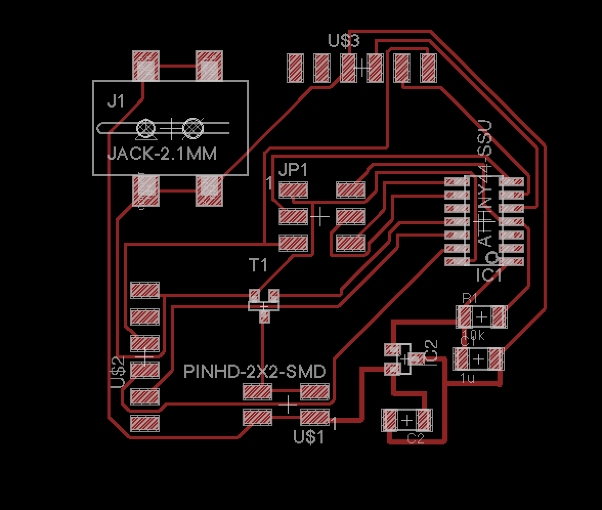
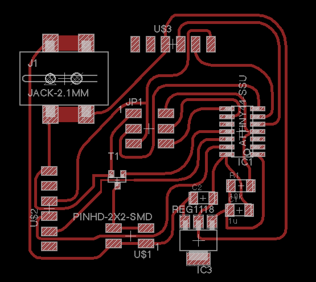
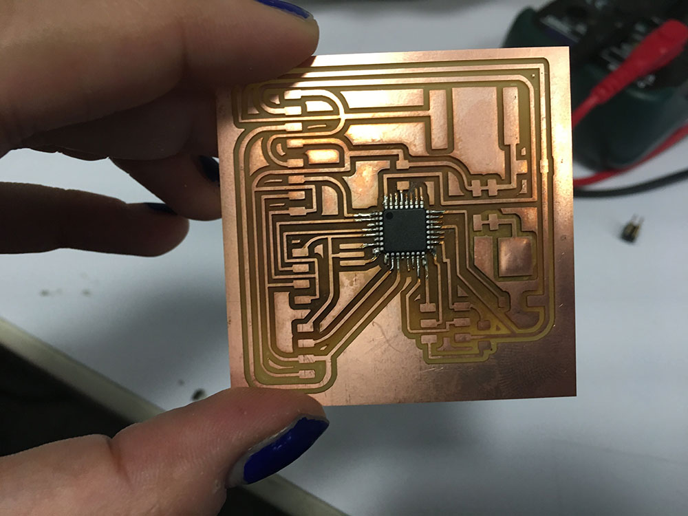
I worked a bit more on the design and added the heat board output to be able to change the temperature for the paint. Ali helped me a lot with the electronics design. I could understand loads of concepts that I was missing. I also managed to route the board without using the autorouter finally.
Soldering the Atmega328p turned out to be quite difficult. Ali showed me how to solder using solder paste. First attempts were not very good but after a bit we managed to get the board ready.
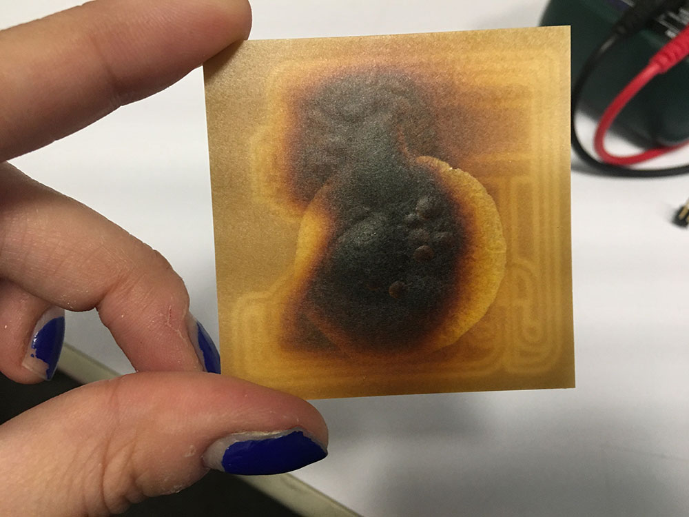
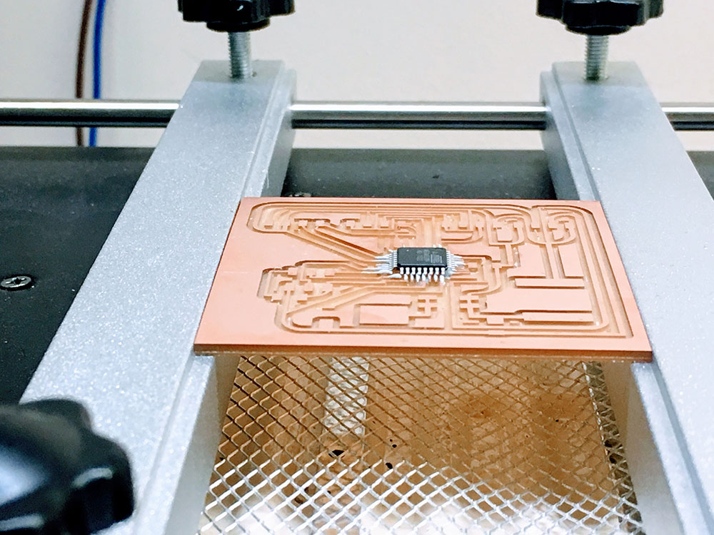
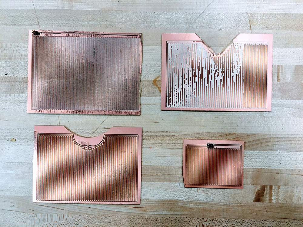
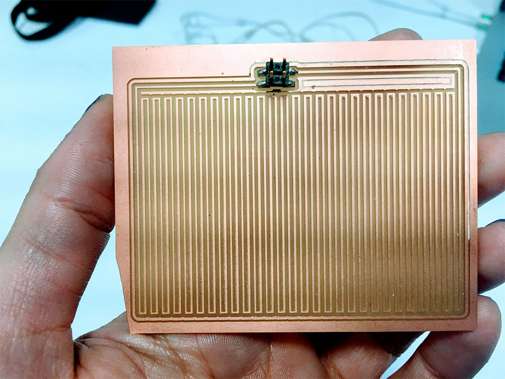
The heat board took me a while to design. I did several tests. I used the Modela and copper boards big enough to cover a whole drawer. First test board was small. It gave me 3.6 ohms resistance which was good for my design using a power supply of 5V. However, I had to design a bigger board to cover the whole area of one drawer. I milled a bigger one but it was not very good. It ended up breaking on the sides and the milling was faulty and not smooth. I had to scratch the board in order to remove the particles attached on top caused by the milling. This board gave me a resistance of 8 ohms. It was a bit higher so the board heated up slower than the first one.
I also designed and tested a small heat board that works fine with one sensor. One of the designs for the heat boards with Eagle:
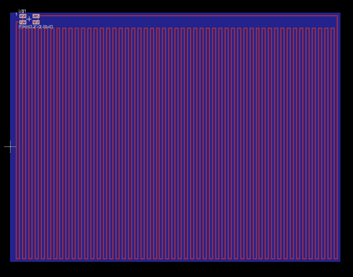
Some other attempts to get the right heat board:
First tests with electronics and paint:

Assembling all the piece and painting it took me more time than expected. The outside structure of the piece is pressfit so I didn't need to add nails or screws. However, if I had more time I would have added them as it would have been more solid. I first sanded all the wood as it was quite irregular. I had to mount the drawers using nails and a hammer. I then added a Gesso layer on the drawer to have a nice look later with the paint. Once dry, I added a first white paint layer. I left it dry and I added a second white paint layer.
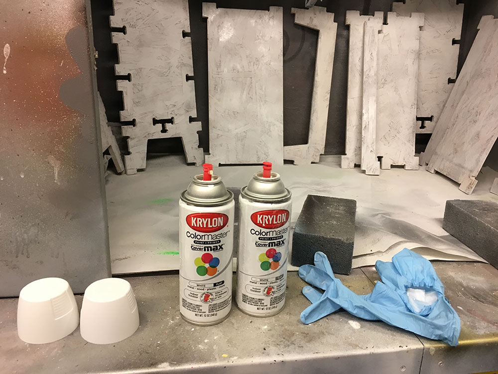
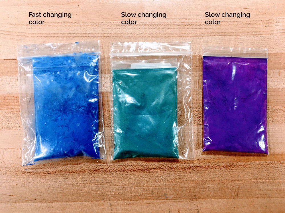
After doing some tests with the thermochromic paint, I ended up using the blue to white color as it changed faster (even though they were all suposed to change at 33°C). So piece of advise, check the changing color speed for the pigments before using them.
Finally, I designed a small interface to be able to visualize what is happening inside the drawers on a screen.