Week seven: Embedded programming
When it learned "hello"...
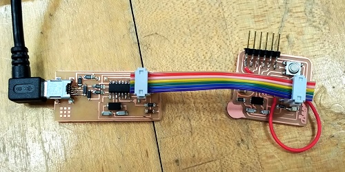
This week our assignment was to play with embedded programming on the boards that we designed in week 5. I programmed my board using my ISP from week 3.
The very first step is to debug your board. I already tried programming my board in week 5, so I knew that I had some problems. What I didn't know was that I had a lot of problems.
My first mistake was using a random page from HTMaA 2015 to figure out the schematic for my board. The schematic was incorrect as it missed many connections, like the one from pin 1 on the ISP to pin 8 on the ATTINY44.
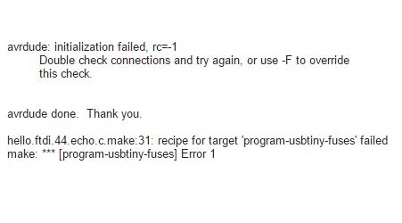
If you receive an error code rc=-1, here's what you should check:
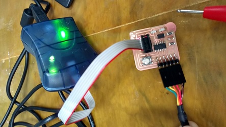
- Your ISP cable. If connecting to the AVRISP the red line should go over pin 1. If you're using your USBtiny then make sure the pin 1's are connected.
- AVRISP code. Green means there are no shorts. Red means there are no shorts, but you need to supply power to the board (via the FTDI cable). Blinking orange means there is probably a short.
- Use a microscope to check for bad connections with the board. Fix any that look sketchy.
- Use a multimeter to make sure that everything is connected the way it was outlined in your schematic.
- Check your schematic. You might have just made a bad design. Like me...
Programming in C
After running the programming files given to us, programming in C is a good way to learn a lot about the board. I edited the hello world program on the website to include reading and writing to pins, like the button and LED pins. Download the c file and the make file then run the program using
Terminal
make -f hello.ftdi.44.button.c.make program-usbtiny
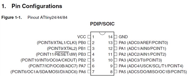
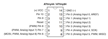
DDRx (x is the port letter) allows you to set the direction of a pin. My LED is on PB2, so I set this as output. My button is on PA3, so I set this as input.
hello.ftdi.44.button.c
// set up Port B Pin 2 as output
//
DDRB = (1 << PB2);
// set up Port A Pin 3 as input
DDRA = (0 << PA3);
You read from a port by using the PINx keyword (think Port IN). The following code reads in the 8 bits of Port A. If my button, pin 3 on the port, is pressed then PINA will read 00000000; If my button is not pressed PINA will be 00001000. This is because my button is pulled up. I AND (&) PINA with (1 << PA3) which means take a 00000001 and shift it left 3 times to give me 00001000. If PINA is all zeros then anding with (1 << PA3) will give me a zero, my button is pressed. Otherwise it will give me a number that is not zero, so my button is not pressed.
hello.ftdi.44.button.c
if ((PINA & (1 << PA3)) == 0) {
Lighting the LED is done using the PORTx keyword. In this case, setting Port B Pin 2 to a 1 will turn the LED on, and setting it to 0 will turn the LED off.
hello.ftdi.44.button.c
// Turn off LED
PORTB = (0 << PB2);
// Turn on LED
PORTB = (1 << PB2);
Programming in Arduino
Programming in Arduino is much easier. If you want to set everything up on your personal computer, I recommend following a tutorial to get everything up and running. This worked for me on Linux.
For whatever reason, Arduino uses a totally different pinout scheme. So set the pins for your LED and button accordingly. Initializing them looks like
Lamp.ino
// initialize digital LED as an output.
pinMode(ledPin, OUTPUT);
// initialize digital button as an input.
pinMode(buttonPin, INPUT);
Reading and writing is similarly intuitive
Lamp.ino
if (digitalRead(buttonPin) == LOW) {
if (toggle) { // if light is on, turn off
digitalWrite(ledPin, LOW);
}}
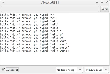
While I was able to use the serial monitor to read the Serial output from the C compiled code, I could not do it from arduino. I received an error Serial is not declared in this scope.And importing avr/io.h and SerialSoftware.h did not resolve the issue.
}