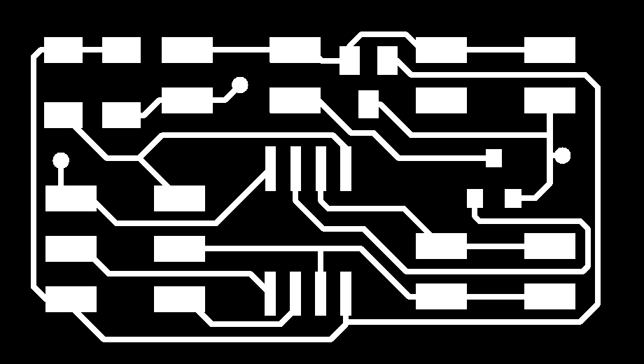
The first thing I did was design the board, mostly based on Neil's board, but with added Tx/Rx lines. I forgot to set the design rules first (I wonder if there's a way to set defaults) so I used GIMP to add spacing between traces before sending the .png to fab mods.


KiCAD Design
Next was actually making the board. I used the via rivets I talked about in Week 8 again. They really are a delight! However, one thing became apparent to me using them this time. Sometimes the rivets removed the traces leading to it, so I would have add a solder bridge between the rivet and the trace. ALWAYS TEST THE RIVETS WITH A MULTIMETER!!! I lost plenty of time when trying to debug the board when it didn't program.

Pretty uneventful
Soldering the pieces was very uneventful. It did become difficult, trying to solder all the jumper pins without burning any of the plastic components of the other parts. The most fun part was making the jumpers between the speaker, the 9V battery, and the header pins. The finished product should look a bit like this:

Final product
Then came time to program. WHen I first plugged in the 9V battery, the voltage regulator started letting out its magic smoke, in addition to AVRdude giving the classic rc = -1 error. THe actual error, as discussed above, was a faulty connection to one of the rivets, which disconnected the ground pin of the ATtiny from the ground plane.
I compiled Gershenfeld's sample C code onto my board, and it worked swimmingly. Except I had no idea how to get it to play more complicated sound samples... Especially not in the literal format that the microphone used, since the program used PWM. In fact, I had started to realize that nothing short of actual analog output would achieve what I wanted.


KiCAD Redesign. Notice all the resistors!!!
I started googling for answers, and found this! An instructable written by someone from the CBA (small world). I highly highly advise giving this a read if you are interested in getting audio output from an ATtiny. I kept the idea of a DAC and then replaced the rest with the amplifier we already had in stock, using the example circuit given on page two of the datasheet.

Final Final product
In code I put a string onto flash using PROGMEM, and got it to play a sound. It was very quiet, so I think I'll try using the high gain example circuit instead. At this point I ran out of time, so all future progress will go towards the final.
Here are the traces and here is the outline for the dumb board that can only play tones. Here are the traces and here is the outline for the cooler board I designed that can play analog sounds. I advise adding an opamp buffer between the amplifier and DAC, because the resistors probably mess things up.