I don't want to spend too much time talking about the design process. I used KiCAD because that was what I learned for Week 4. I remembered to change the design rules first, so that was pretty nice. Also, we got via rivets!!!!! And double sided FR1!! I wanted this for a long time because I was annoyed by having to place so many 0Ω resistors to bridge everywhere, and having a ground plane would hopefully change that. I started with Neil's sample mic board and combined it with his serial bus bridge board so I could reuse this board for the networking project.


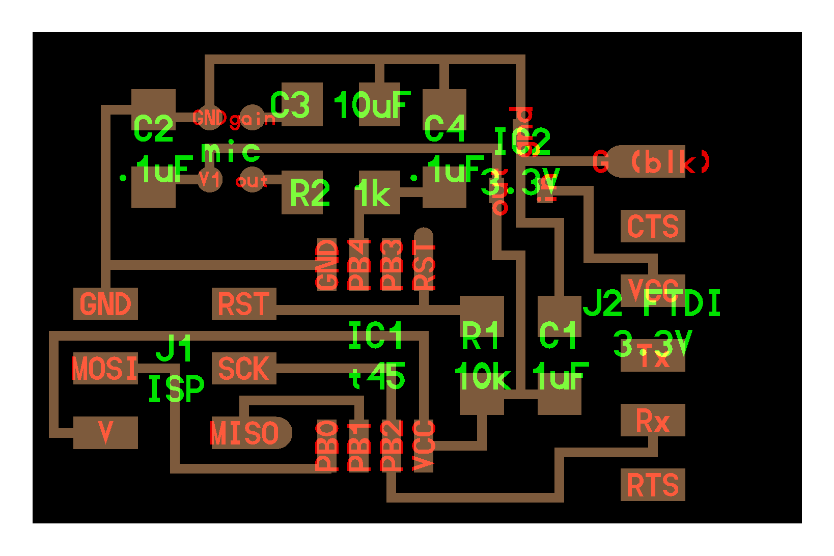
EESchema and PCBNew
With the design completed it was time for me to actually make the circuit. And to help me was the new rivet machine! Gavin and I opened the box for the first time and set up the machine. And it was quite easy to use too! You just put the rivet through the bottom such that the non-lipped end points upward, align it with the machine, and press.


Using the new rivet machine
And the multimeter confirms that the connection between the sides is good, which means I can go forth and solder my materials. The next obstacle to making my board was soldering on the MEMS analog microphone. The contacts were all on the back, so it needed to be reflow soldered. I assumed it would be so much more difficult, but I actually found it pretty easy. You simply put some of the paste onto the leads, stick it on, and apply a concentrated heat gun. Gavin suggested I use tweezers, but I was able to get it to work without them.


My first attempt at reflow soldering
Next was to try to program it. After reading more of the datasheet (hint: just look up the registers that are mentioned in Neil's code to see what each of them do), I got a pretty good sense of what his code does. So much so that I could probably explain to a friend what each line does (with reference to the datasheet of course). When Gershenfeld says to just read the datasheet, I really agree with him (but moreso on a need-to-know basis. Reading all of it at once is crazy). At first all I did was have the board constantly send information via serial, and then read it off via rx.py and hello.SPU0414HR5H.py . What I eventually just did was rewrite rx.py to write the data to a .txt file and then plot it. After recording me alternating between a high pitch and a low one, I got the following plot:

You can see where the frequency switched from being high to low!
Afterward, I set the ADLAR bit in the ADMUX register to 1 so I could just read off one register for 8-bit ADC accuracy, because I realized (after reading the datasheet) that the ADC gave 10-bit accuracy, and I was reading from two 8-bit registers, one of which would consistantly give me constant-ish values. I might want to change this because the values it reads are consistantly high, and reading the lowest bits gives me a more reasonable range of values.
Here are the traces and here is the outline. Also included: my new rx.py, my plotting script, and the .txt file mentioned above.