I started by researching how the mechanism worked, so I could start to plan it/understand what each part was doing. I knew the general idea, but I needed a very firm understanding to actually build it. This was one of the first sites off Google, so I just went with it. Also, can't forget about Wikipedia, the most trustworthy site on the internet. Next I looked up examples of home-made pendulum clocks, to see what designs people adopted and what to take into consideration. I settled on the first instructables I found, which didn't give step-by-step instructions, but moreso served as a journal for the creator (much like this website!)
Desine
The general idea behind my design is that there are four main axles, arranged in a square (see bottom of design). Each pair of gears has a certain ratio of teeth (x4, x5, or x6), and their radii have to add up to the side length of the squares. In addition, I wanted the ratio of #teeth/radius to be as equal as possible between all the gears. To do so, I made a spreadsheet of all possible teeth number that would accomplish this. The gears have to be large since the 1/4" endmill restricts how small the distance between teeth are, I need teeth that are wide enough to be sturdy, and the distance between teeth need to be big enough to fit the teeth of an adjecent gear. Thus, since the axles will always be too close to the gears, there'd be four planes of gears.
One gear would be special because it'd have another coaxial axle, and these two axles would handle the minute and hour hands separately. I planned to use wooden dowels and PVC pipes (attached like this ) as my axles and axle holders/coaxles, and I used a PVC pipe diameter table to decide on using 1" wooden dowels and 1" Schedule 40 PVC.

SO MANY GEARS
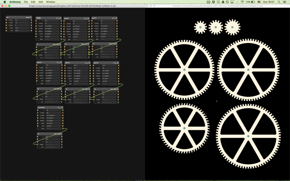
CADing the designs was fun for two reasons: 1) it was my first time CAD'ing gears and 2) I got to make signnificant use of the blend node! I used Antimony yet again for not reason other than the fact that I was most comfortable with it at this point (which should be scary). Other CAD softwares probably had gear generators already preprogrammed, but I wanted to CAD the gears myself for this project. I made each gear using an annulus, polar arrayed rectangular teeth, and rotated rectangles all blended to gether to make it more structural and pretty.

No one will be able to tell that I'm making a clock
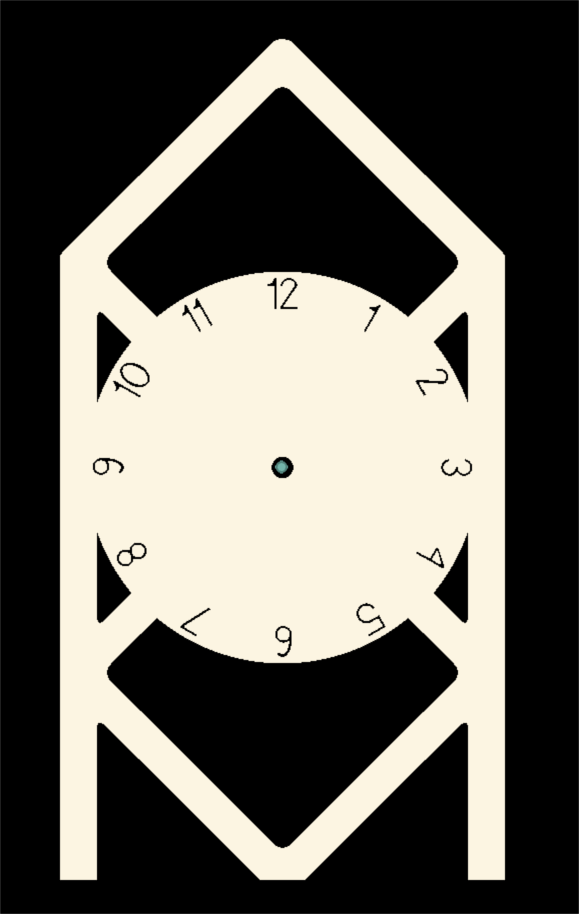
I also got to use the text node in Antimony for the first time to make the numbers on my clock face. I got used to taking the kerf into account from laser cutting because the software that laser cuts doesn't take kerfing into account for you. However, this made it difficult to visualize how thin my structures would actually be, because having the kerf on two sides of something adds half an inch, which is significant for something that's already small, like the gear teeth. Sometimes I would set the kerf parameter to zero just to see what they would actually look like. What I didn't realize at the time was that the CAM software can cut on the outside or inside of your design so that the kerf is taken care of already!

Final redesign
I had to go through several redesigns because of physical constraints. Again, because of the constraints of having a 0.25" endmill, plus the fact that the pendulum itself has to be of constant length (~ 1 meter) meant that everything had to be pretty big (which is good since that is the goal of the project). My original design had meter wide gears and a frame that was 5' wide, which wouldn't fit the 4'x 8' OSB sheets we were given. I then made it smaller, but realized during my scheduled cut time that everything wouldn't fit on two sheets, so my final redesign made the largest gear ~2' wide, and the bulk of the frame would be to accomadate the pendulum. Each redesign took less and less time, because parametric CADing is amazing. However, this would all have been solved before my cutting time if I used a CAM software to arrange my cuts beforehand. I think it should be stressed more in class how important it is to CAM your cuts before coming to the shop (especially for the EECS section, which doesn't have its own large shopbot).
I should just make these part of my door
Gavin was able to schedule a slot to cut at Edgerton after week 5, but I didn't get to cut my entire design before he had to leave. I did get a few pieces cut, which will look pretty nice on my door :) It's great that the gears turned out so well, since they seem to interlock perfectly. If I get access to a large shopbot in the future I might just finish my design!
Here is the latest Antimony file. Refer to the mess that is the 6th paragraph (not counting intro) of Week 1 in order to figure out how to get .png to .dxf! The latest Antimony file fixes the problems of the design I used for my cut, such as making the numbers larger so the mill could actually cut it and making the frame generally nicer. I suggest cutting the kerf entirely and making the teeth on the pendulum top pieces and the speciall pendulum gear wider. And here are the VCarve files, arranged perfectly on two 4'x 8' sheets, ready to be cut out and abused by the world.