final project tracking
The Idea
My idea for a final project is an interactive music box, which could serve as a learning toy for children. The main structure would be a box, with a musical staff present on one side of the box, or could even be a flat surface. There would be five horizontal lines across the box/sheet to signify the musical staff, either colored black or actually protruding from the surface. The interactive part would be musical notes, which could be placed onto the staff to make a short composition of music. Then, by clicking a button, a series of notes would be played back, accurate to how the physical notes are arranged.
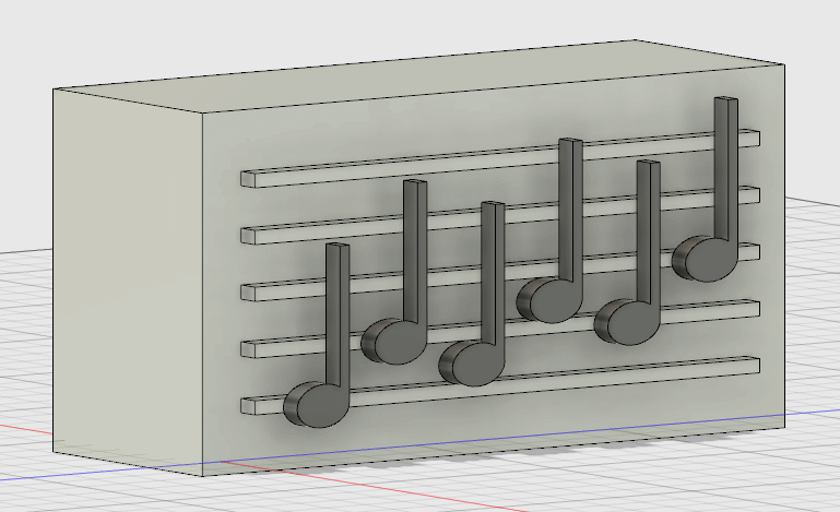
Initial final project idea in Fusion from the first week.
Update 10/17
Today I started talking to the TA Grace about my final project idea. I am a total newbie to everything in this class, and I knew that the idea I have will rely heavily on input (sensing where the notes are placed) and output (playing back the notes), and we haven't gotten to those weeks yet, so it was helpful to talk to Grace about possibilities. We mainly talked about possibilities for how to sense the notes, and have three options, each which has pros and cons.
- Closing a circuit: If the box had a carefully-designed vinyl cut copper circuit on it and the notes were backed with copper tape, then placing a note onto the box could close a circuit. However, this would require notes to be placed in very precise locations, and there would be a copper tape circuit on the box, which might make it look less like a musical staff.
- Switches: The box could have a switch for each location where a note could be placed, and placing the note could toggle the switch so that it could be sensed. Again, this would require notes to be placed somewhat precisely, and there would be switches all over the board.
- Distance: Grace showed me this video which uses the hello.HC-SR501 in sonar distance sensing. I could sense the location of one note with one (or two) of these distance sensors. One problem is that sensing x notes would require x of these distance sensors.
Update 10/31
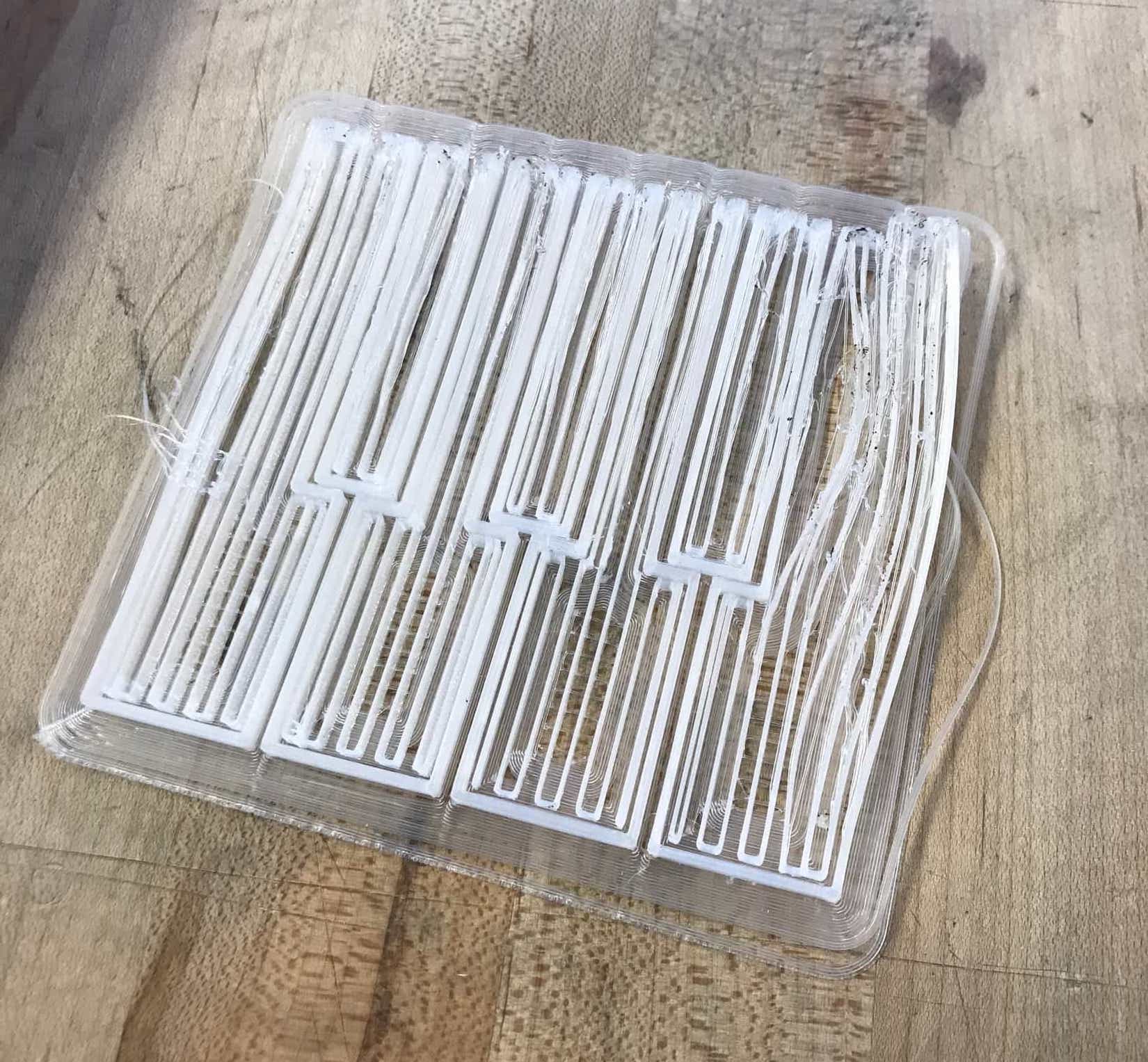
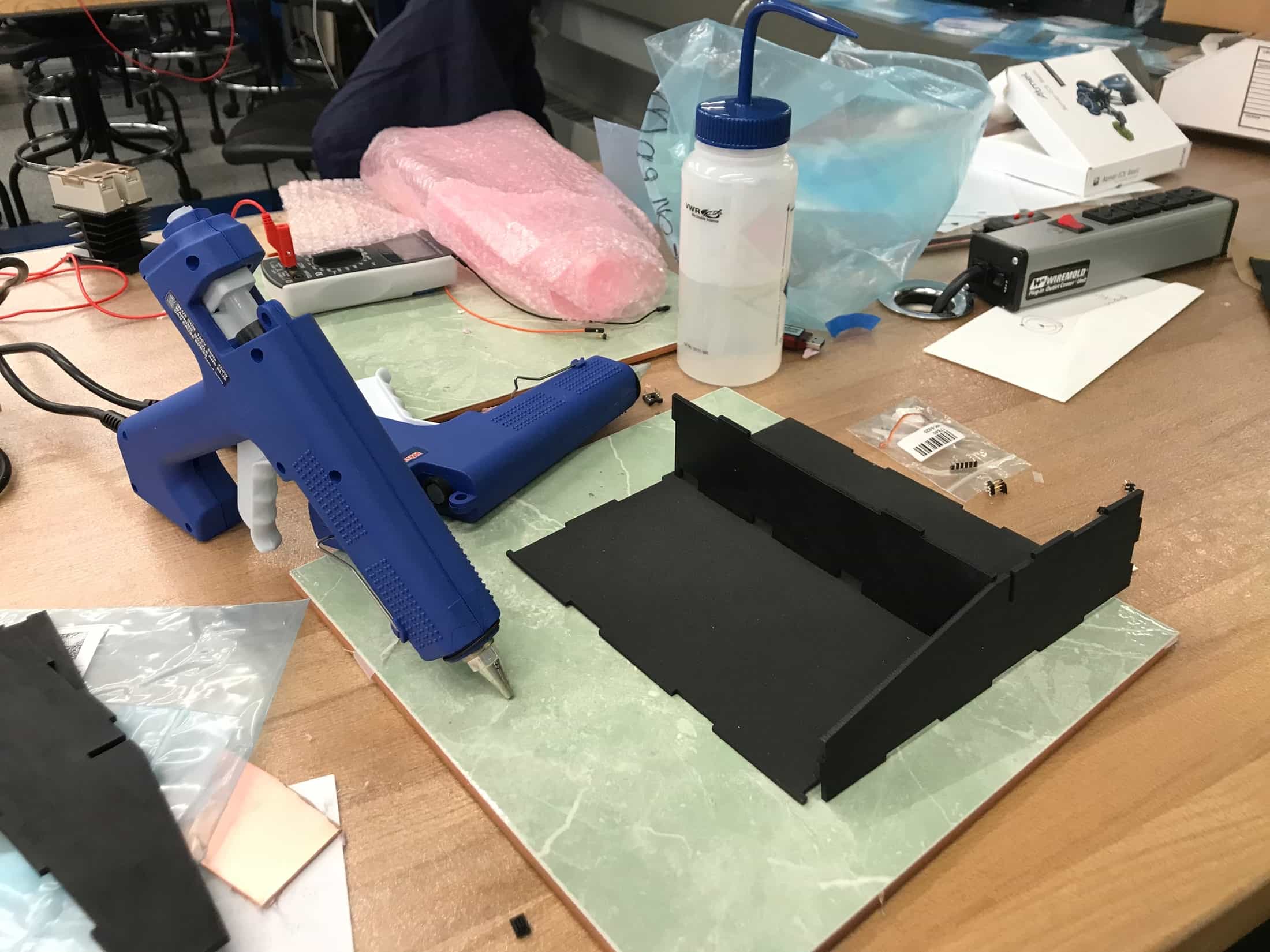
This week was molding and casting week, and I made a mold for and cast some music notes, with the possibility of using them in my final project. I might have to mirror the mold so that the back part of the note is the completely flat part.
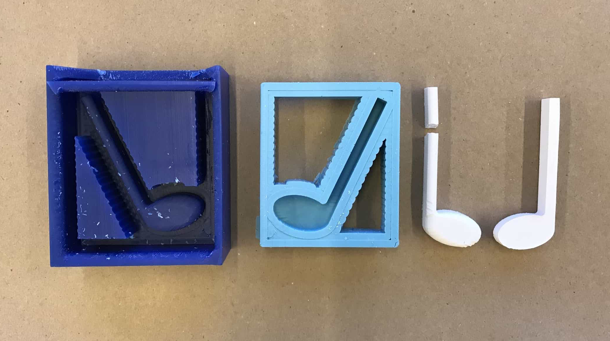
I made a mold for and cast music notes.
I'm still debating about the input sensing for my final project, because I think there are problems with each of the three possibilities I discussed with Grace. I looked ahead on the class website to Input Devices week and it seems like step response is the recommended way to sense position. I think this capacitive multitouch grid by Matt Keeter accomplishes position sensing that could be modified for my project, so I am planning to build/test that soon.
Next week is Output Devices week, and I'm going to make the output device I add to my board be a speaker, so I'll have a start on the electronics for my final project.
Update 11/7
I tried to make a speaker this week during output devices week. It was a huge struggle and didn't work. I'm not sure why, and TA Mike also isn't sure why. More details on my struggles with the speaker are in output devices.
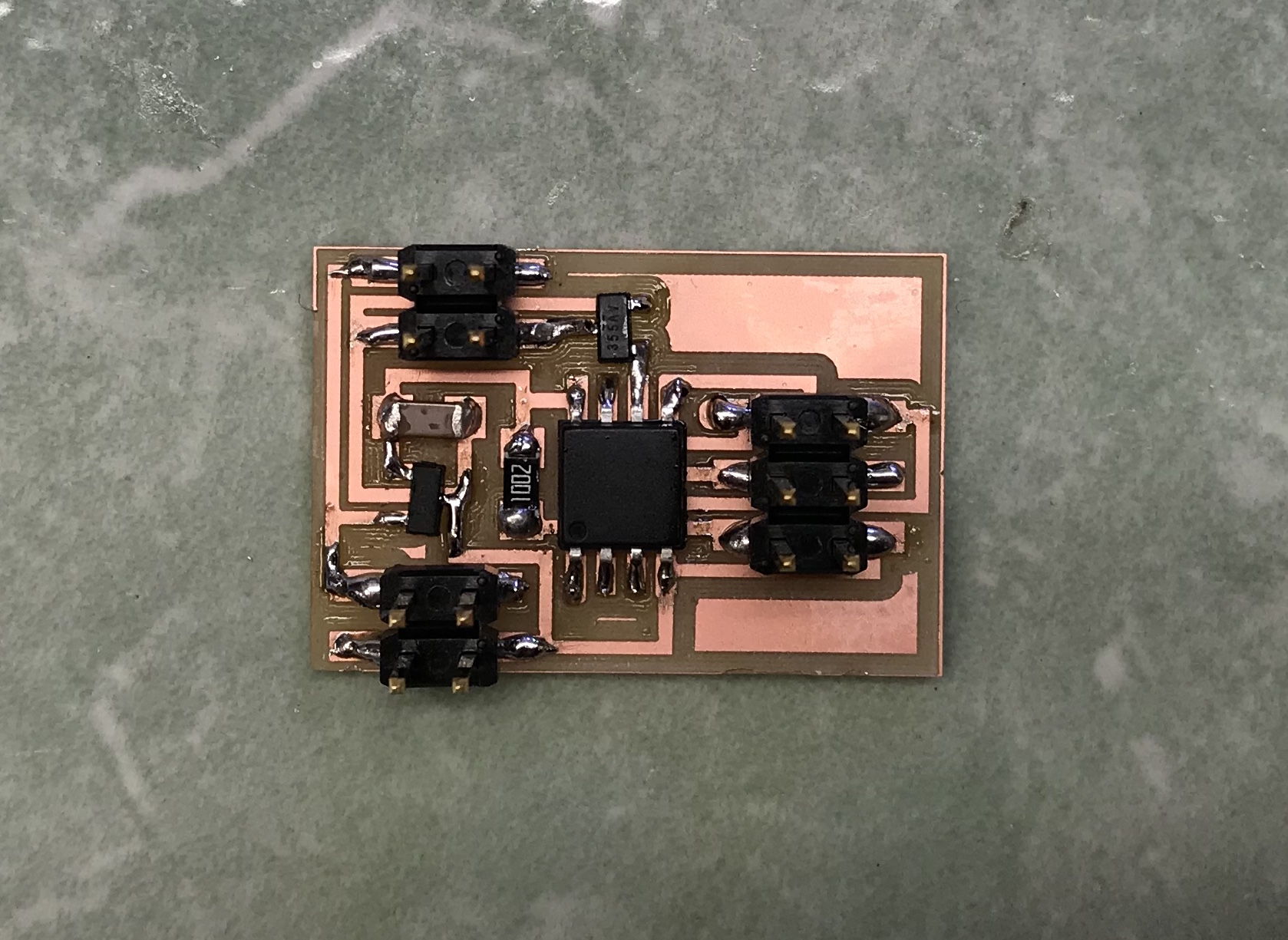
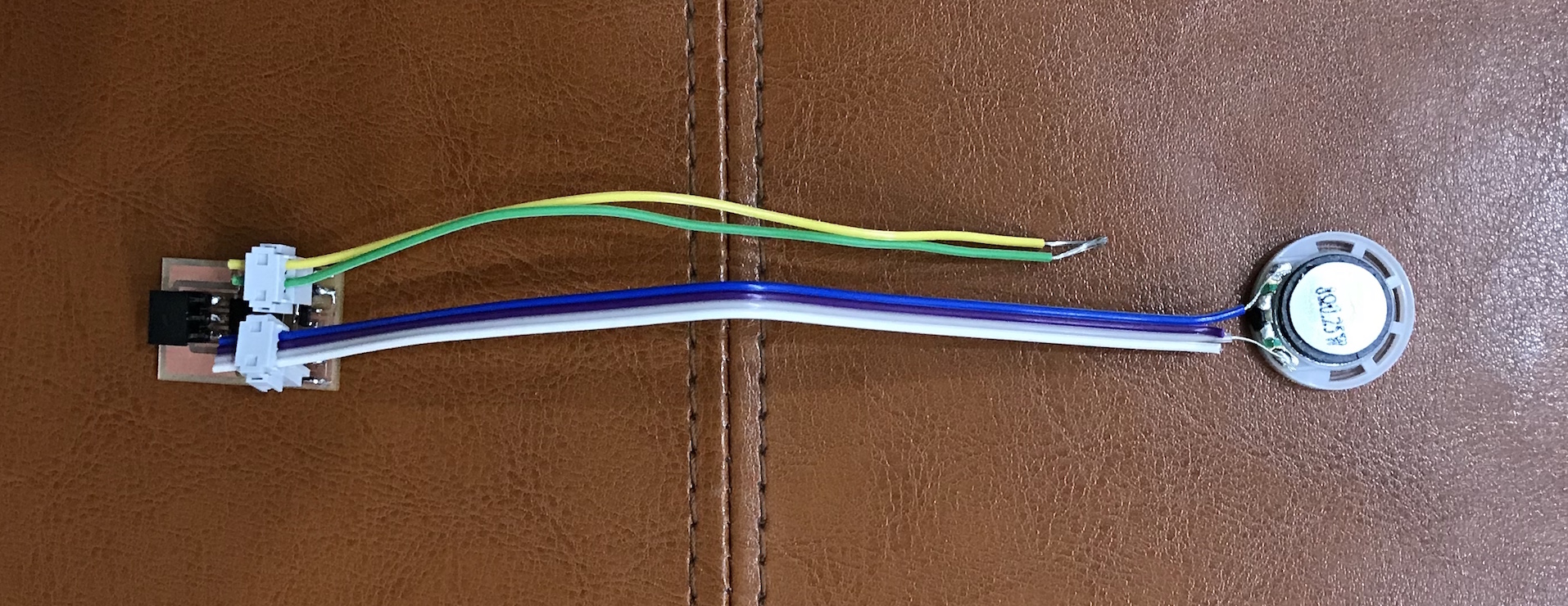
My attempt at the speaker board which failed.
Update 11/21
I attempted to make boards for step response and capacitive touch sensing this week during input devices week. I milled two boards--one for single touch and one for multitouch. I didn't stuff the multitouch board yet, but I did stuff the single touch board and it sadly did not work. I have to come back to this.

I haven't gotten the first capacitive sensing board to work yet, and I haven't stuffed the second which is for multitouch.
Update 11/24
I think I need to simplify my final project idea. It relies so heavily on sensing where music notes are placed, and I haven't been able to get step response to work yet. It also requires sensing a lot of different locations, because there are 9 possibilities for where a single note can be placed on a staff ignoring above the top and below the bottom line, and I would also want to sense more than one note. I think I have a modified idea which I like better. Instead of having the physical object be the sheet music, I want the sheet music to be the computer interface. The physical object will be a mini piano keyboard. A user can use the application to place notes or preselect a song, and then the piano keys will light up according to which one should be pressed when for someone trying to play the song or sequence of notes in the application. I plan to have 12 keys total, and I can use charlieplexing to control these LEDs in the keys. I am fairly certain I can get the LEDs to light up according to a sequence of notes, so the next extension I would like to add to the project (depending on time) would be sensing and a speaker. Each note, in addition to having an LED, would have a capacitive sensor, and I could use the speaker to play the note as someone touches it.
Update 12/5
I started a Processing sketch for the computer interface part. Right now it's a screen with five horizontal lines.
This week was networking and communications week, and I got charlieplexing to work, which is how I am going to control the LEDs to embed in my piano keys, and I also created a wired serial network that I am going to use in my project. I can use my bridge board in my final project. I will need to modify the node board for my final project so that it can control 12 LEDs instead of just 6, and so that the LEDs are external rather than surface mount.
Charlieplexing and networking success.
Update 12/7
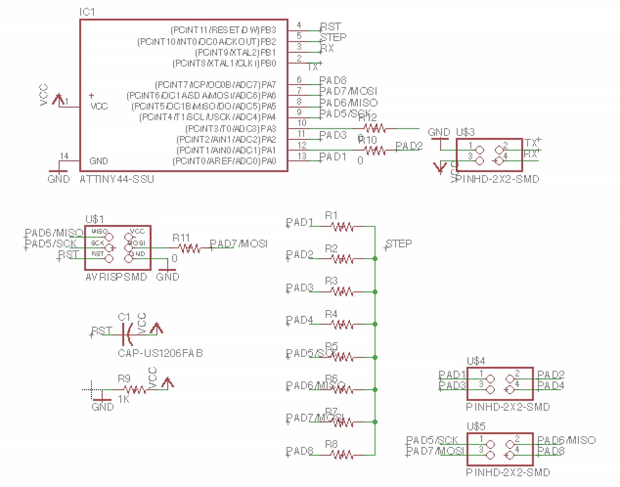
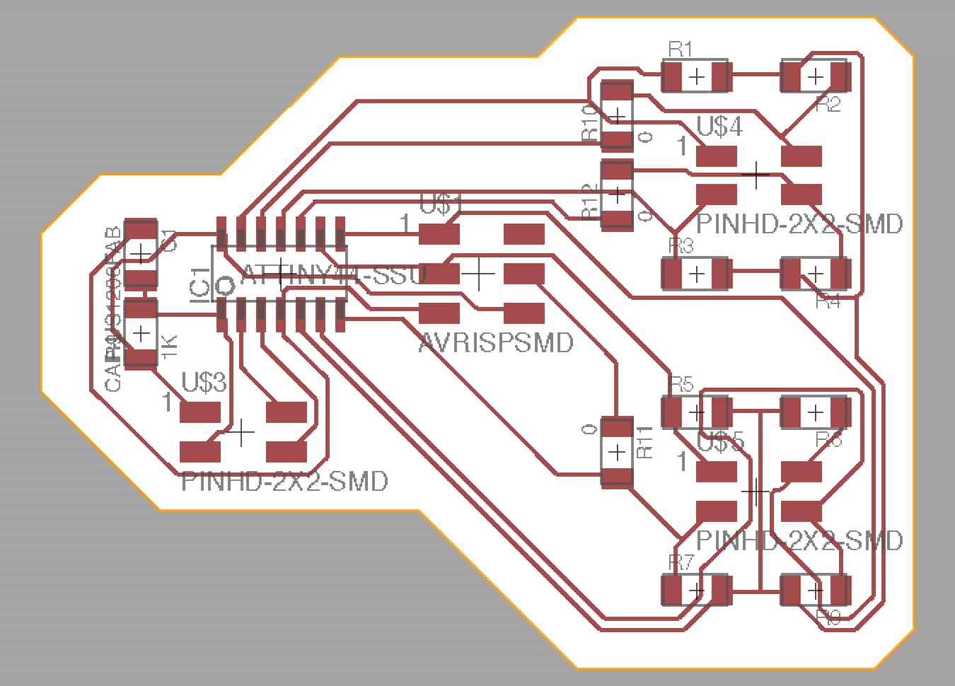
I have designed one of the node boards for my final project. This is the board that will control the LEDs. The board has pin header connectors which will connect to twelve external LEDs which I am going to embed in piano key objects to light them up. I still need to design another board which will handle the capacitive pressure sensing for each key.
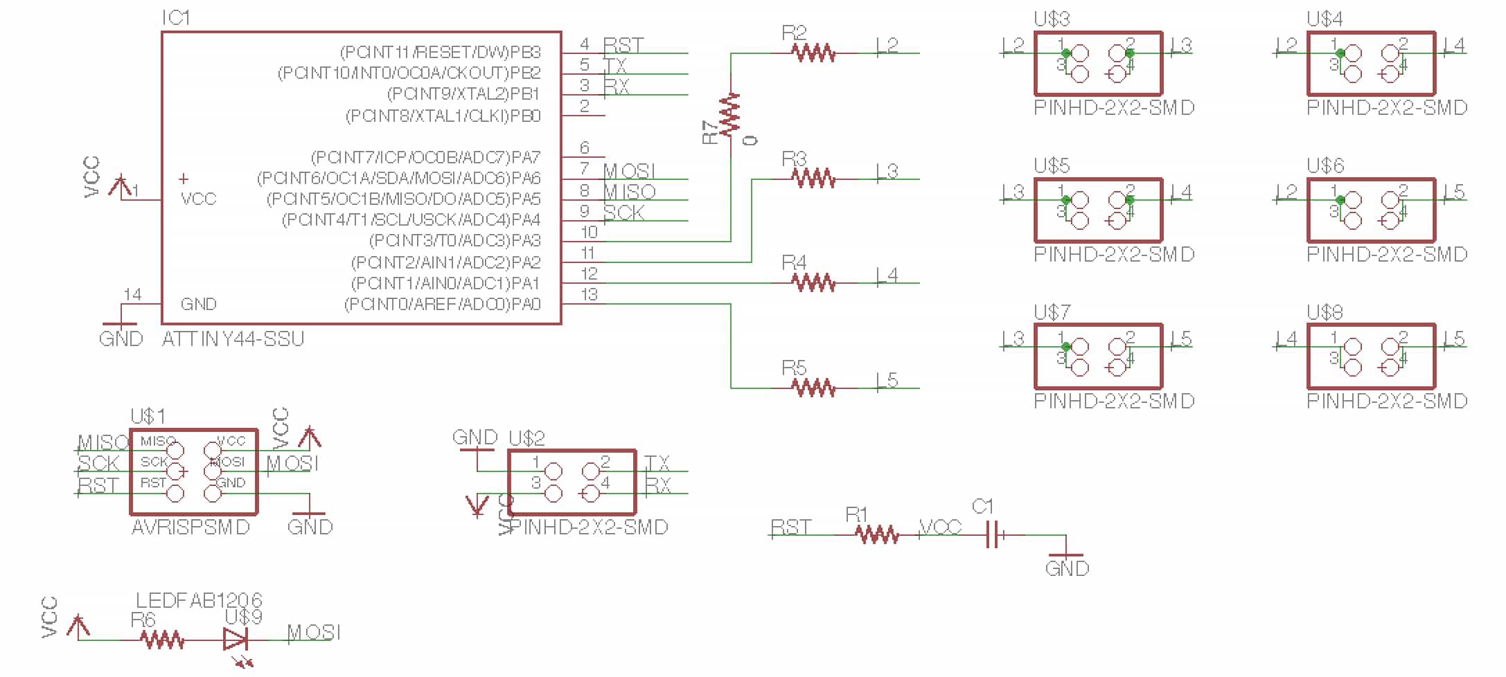
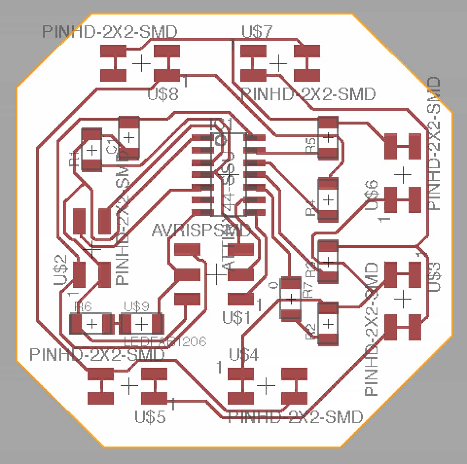
Design for node to control the LEDs with charlieplexing.
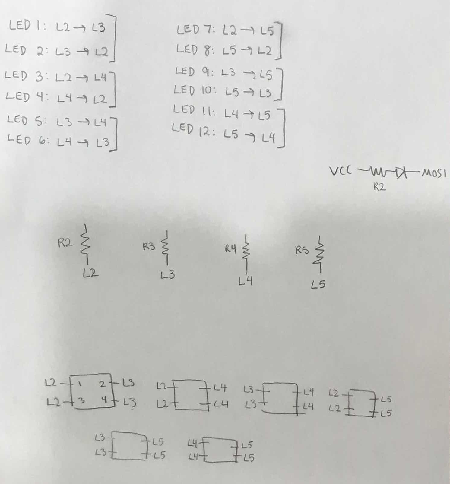
Drawing out which LEDs will connect to which pins.
Update 12/13
I'm done with all my other classes and now it's crunch time to do this final project. Today, I wanted to get a good start both on electronics production and on physical part design. I started with electronics.
I had already designed my board for controlling external LEDs with charlieplexing, so I milled that board on the Othermill. Ben had recently emailed out saying that the 80 degree metal engraving bit was working better than the 1/64 end mill on the Othermill recently, so I first milled the board with the metal engraving bit. The board didn't come out super clean, as it seemed like the bit cut deeper than necessary. I also noticed that my traces were really thin. I thickened my traces in Eagle and remilled the board, this time trying the 1/64 end mill to see how it compared to the engraving bit. I ended up using the second board, but I agree with Ben that the metal engraving bit is cutting boards more cleanly. For this second time, I also used the feature of the Othermill software which detects the material thickness.
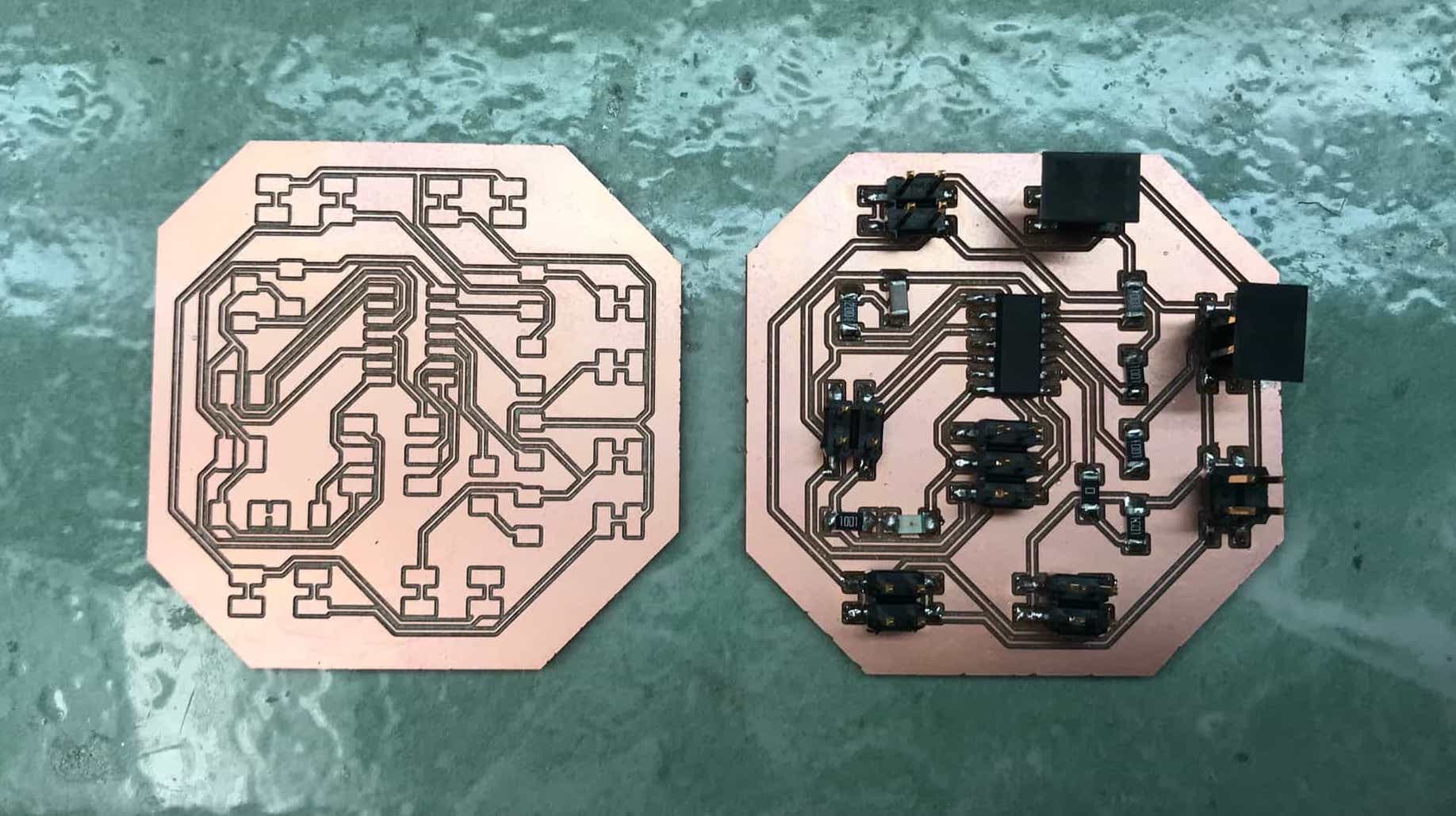
My two milled LED controller boards, one after stuffing.
I also wanted to start some of the design of the physcial parts of my project today. I am still debating what's the best way to create the piano keys. The two best options I see are:
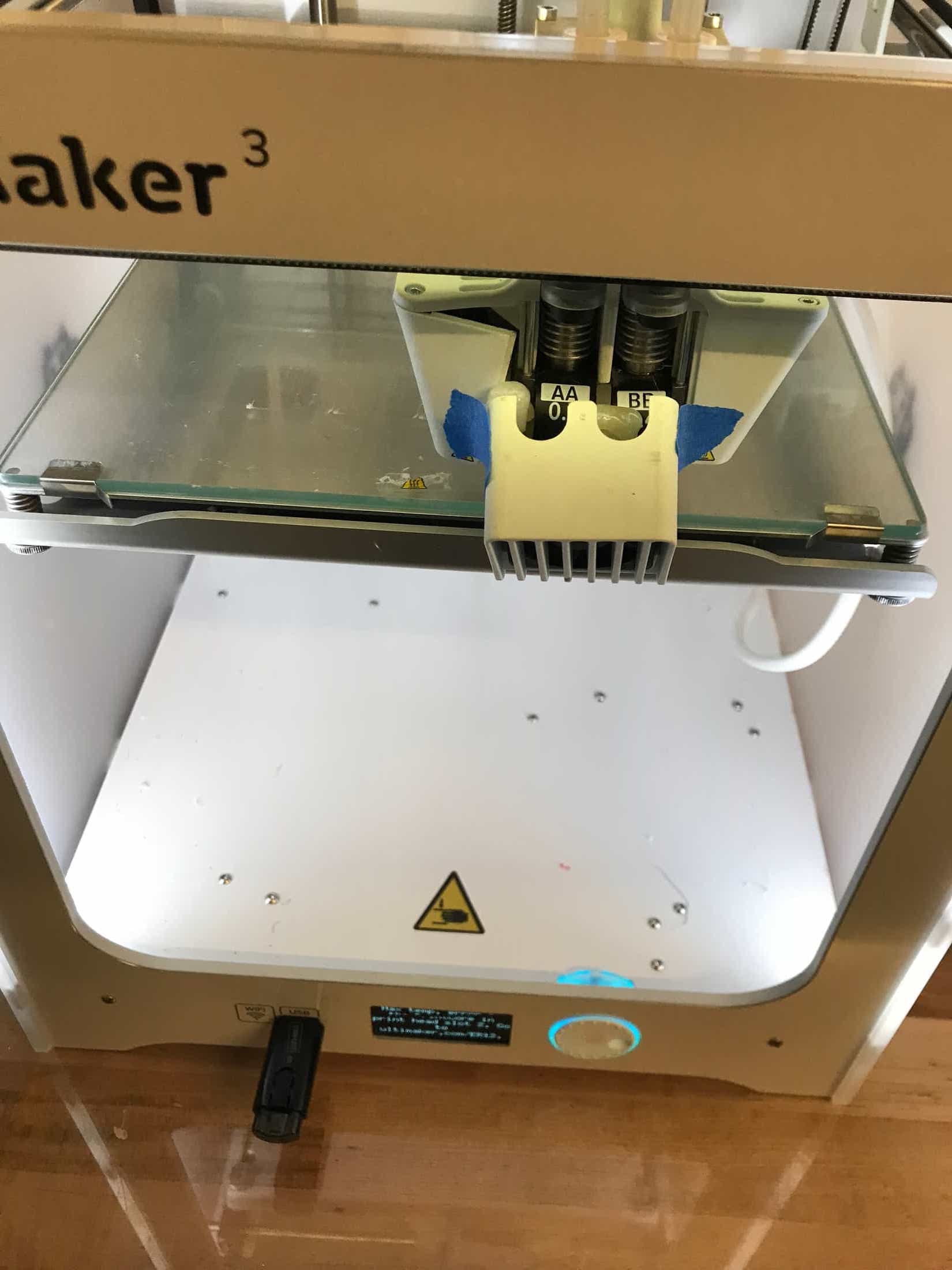
- 3D print them. I could design them to be hollow so that LEDs would fit inside, and I would need them to be transparent/semi-transparent so that LEDs would be visible. I don't think any of the 3D printers in EDS have clear filament, but I have access to the IDC and the self-serve Ultimaker is currently loaded with clear filament.
- Make the keys by molding and casting. I don't know how to mold something to be hollow, but I could make the mold solid and embed the LEDs inside as long as the mold material is semi-transparent so that the LED light is visible. I've been looking at Shirin's final project page for her brain project from last year, and she did something like this. My molds would need to be two parts so that I could place LEDs in the middle of each key. I could 3D print keys, surround them with Oomoo, and attempt to create two-part molds for the keys, or I could machine a two-part mold from wax and use that to make the mold. Sorta-Clear is the option for clear casting material that is in stock in EDS, so that would be the material I'd use to actually create the keys. It might be too transparent though, and I'm also not sure about its hardness. Shirin said she used Moldstar 20T which is less transparent, but she said that it doesn't cure in Oomoo.
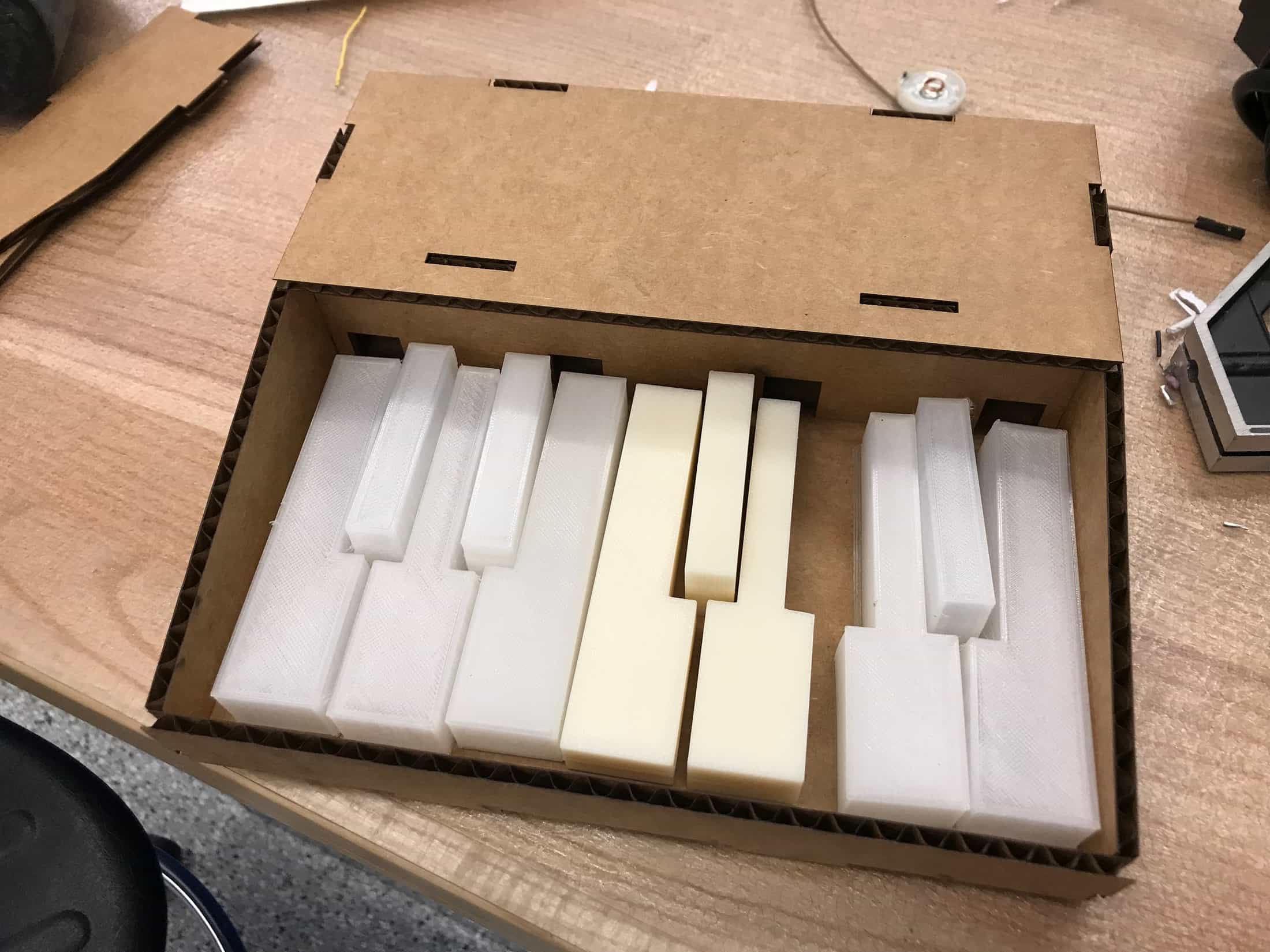
I decided that 3D printing a couple test piano keys while I was working on electronics things would be a good start. I took a look at the design files for these piano keys on Thingiverse. I imported the STL into Rhino, outlined the edges, and extruded the shapes so that I could work with them. For my first attempt at 3D printing, I would be using the Stratysys in EDS, and since that doesn't have clear filament, I didn't care about making the keys hollow. I mostly just wanted to test out the size and feel of the keys. I started a print of three keys. When I retrieved them a couple hours later, they had finished and turned out really nicely.
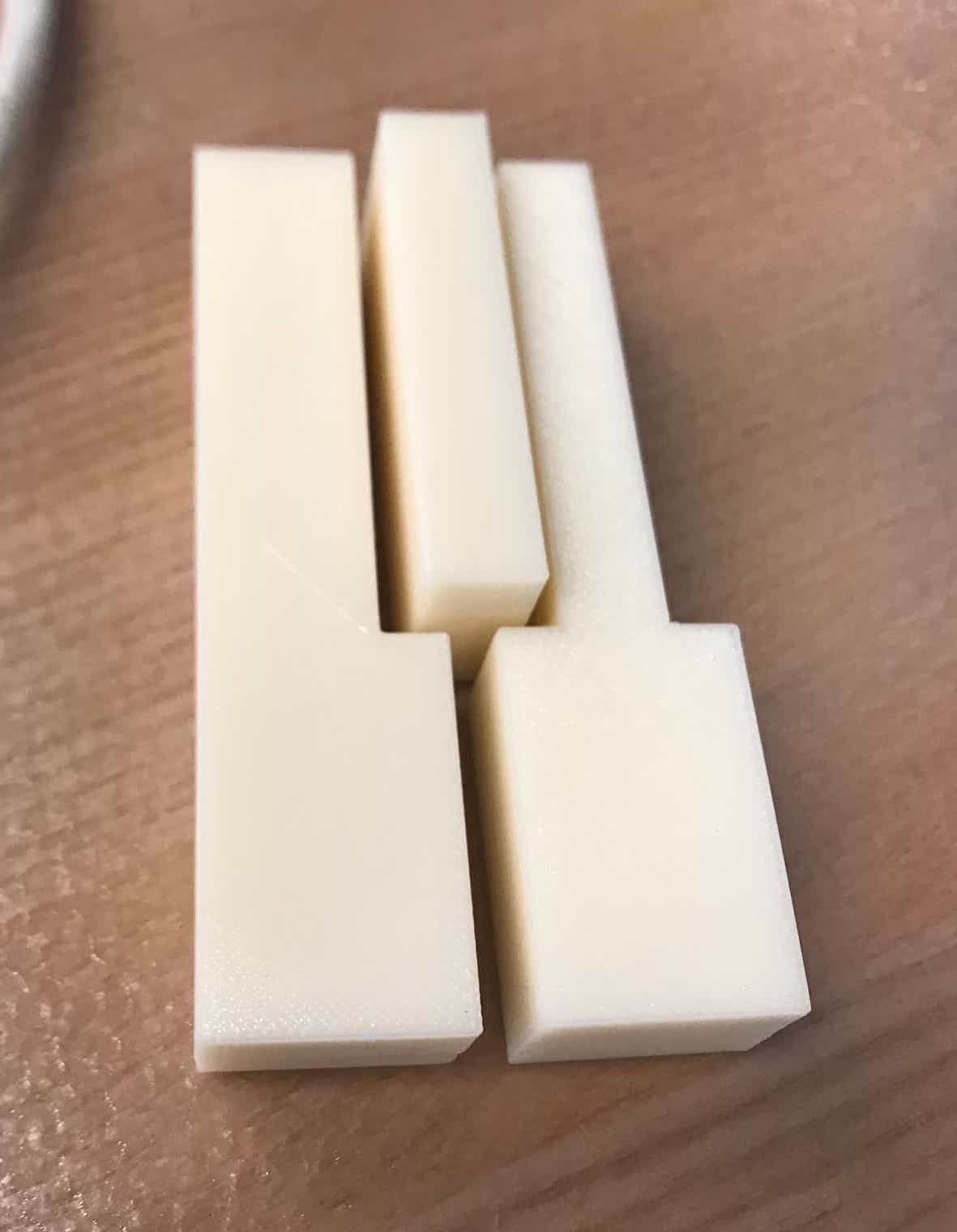
The test keys I 3D printed on the Stratysys.
I had finished soldering my LED controller board, so I wanted to see if I could program it. Attempting to program a new board is always the moment of truth, and has been the main struggle for me during this class. But my last 3 boards had been successful, so I was hoping that was a good sign that this one would work. And it did! I was able to program it with some random program not actually written for that board. My board has a surface-mount indicator LED connected to one pin of the ATTiny, so I wanted to make that blink. It took me a bit to get that working because I was mixing up pins, but I got it and considered that enough success for Wednesday.
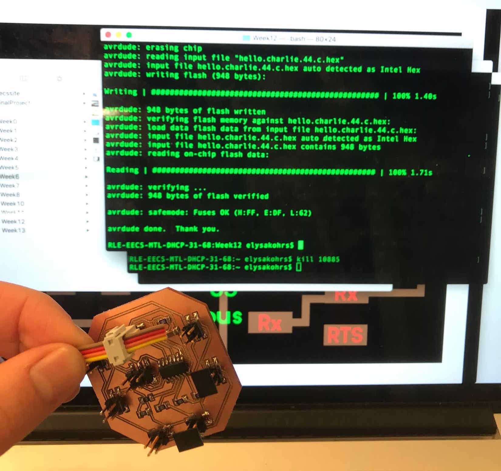
I love when I can program my boards.
Blinking success.
Update 12/14
Again, I worked both on the electronics and physical sides of this project today. The 3D printing had turned out well from Wednesday and the machines for milling wax were in high demand, so I continued on the 3D printing route. I wanted to use the Ultimaker in the IDC because it has clear nylon filament which should be sufficient for LED light to be visible through. In Rhino, I took the solid piano key shapes and hollowed them out. I added a hole in the back which I could run wires through, and made the front and back portions of the bottom but left the middle empty so that I could access any electronics inside the keys. I used the Ultimaker software to plan the print and generate supports, and then started the print mid-day.
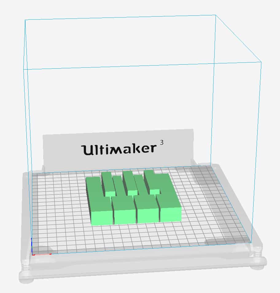
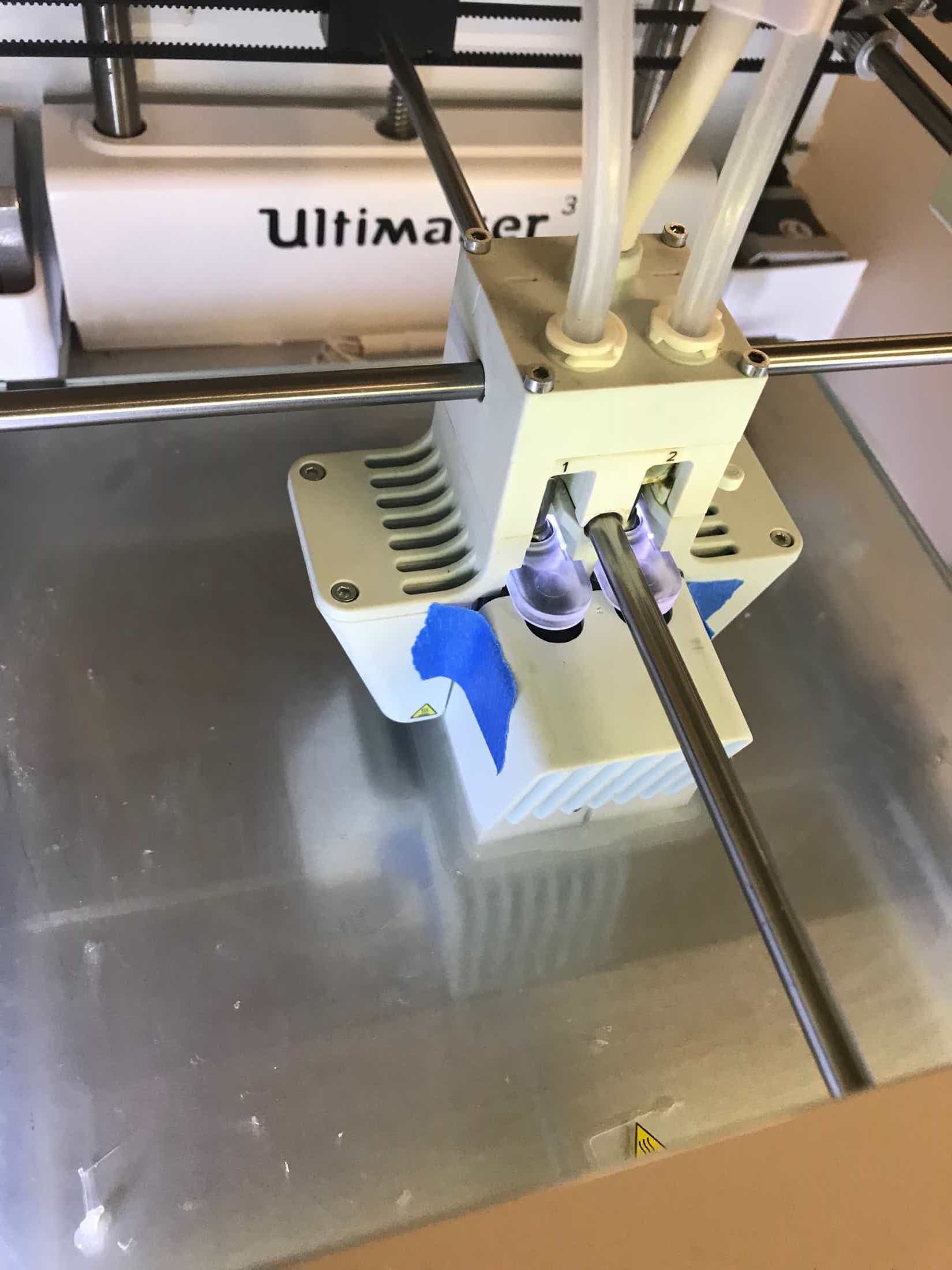
Preparing to use and using the Ultimaker.
Back to electronics. I knew from yesterday that my board can be programmed and that the LED on the board works. But the main goal of this board is to be able to light up specific external LEDs connected to the pin headers. I grabbed some through-hole LEDs from the stock room to test with. My C program was a combination/modification of Neil's charlieplexing code and Neil's code for a serial bus node. I set up some jumper wires connecting pins on my board to an LED, and tried to make my board respond to its id by turning on that LED. At first, I thought it wasn't working, but I realized that the LED was super dim and I just hadn't been noticing the LED flashing on and off. I knew I could lower the resistors I was using on my board, but wasn't sure how much of an impact that would have on brightness, so I also tested brightness of some SMD LEDs. I decided that the SMD LEDs would be sufficiently bright for my purposes.
The LED turns on in this video and you can't even tell because it's so dim.
The SMD LEDs are sufficiently bright.
I left EDS for a few hours in the afternoon, and when I came back later I got out my board to do some more experimenting and discovered that one of the pin headers had gotten ripped off my board while it was in my backpack. Only half of one of the four pads was still on the board. I asked a few different people for advice, and Gavin suggested that I try to solder the original pin header back to the board at the half-pad. Since the rest of the pads were mostly attached to the pin header, I could try to reconnect the pins/pads to the traces still present on the board. It took a good amount of time and required a slightly sketch jumper cable and some X-actoing of a new pad, but I successfully restored my board to its full working glory. This surgery on my board ended up taking up my time until EDS closed, so I didn't actually get to experiment much more with the external LEDs.
Before and after surgery on my board to fix the header that got ripped off.
I went back to the IDC to check on my print on the Ultimaker. It was looking fine, but not very close to finished, so I planned to pick it up in the morning.
I did some design work at night. I still wasn't entirely convinced that I would use the 3D prints from the Ultimaker since my prints hadn't finished yet, so I wanted a backup plan. My backup plan would be molding and casting. I would need a two-part mold in order to embed the electornics in the middle, so I used Rhino to design a two-part mold. I had only done a one-part mold during molding and casting week, so I had to think a lot about whether I was getting the positive and negative right. I also created protrusions/indentations to fit the two sides of the mold together, and I added holes that extend to the edge of the mold for filling the mold. I ended up with this design that I could machine and mold if/when I want to.
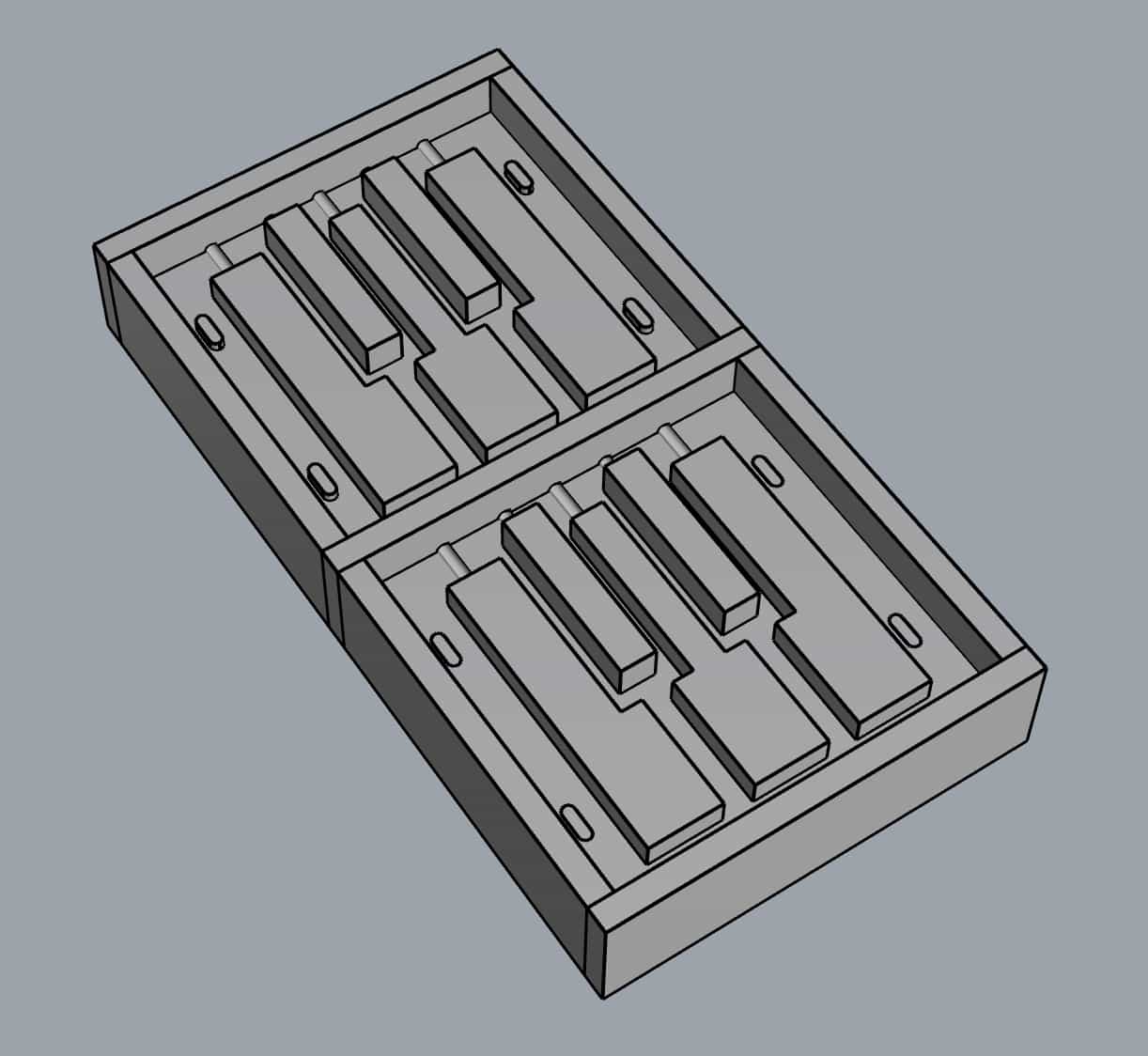
Design for a two-part mold for the piano keys.
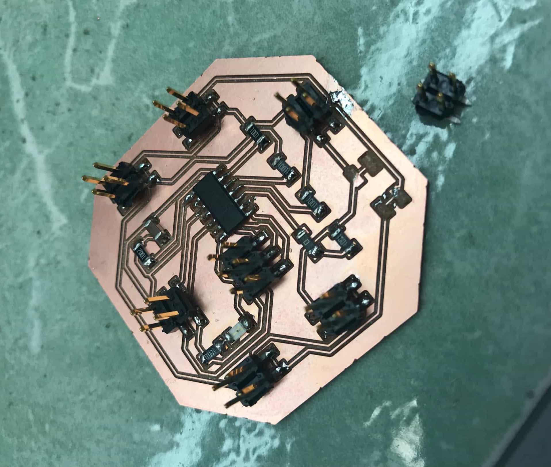
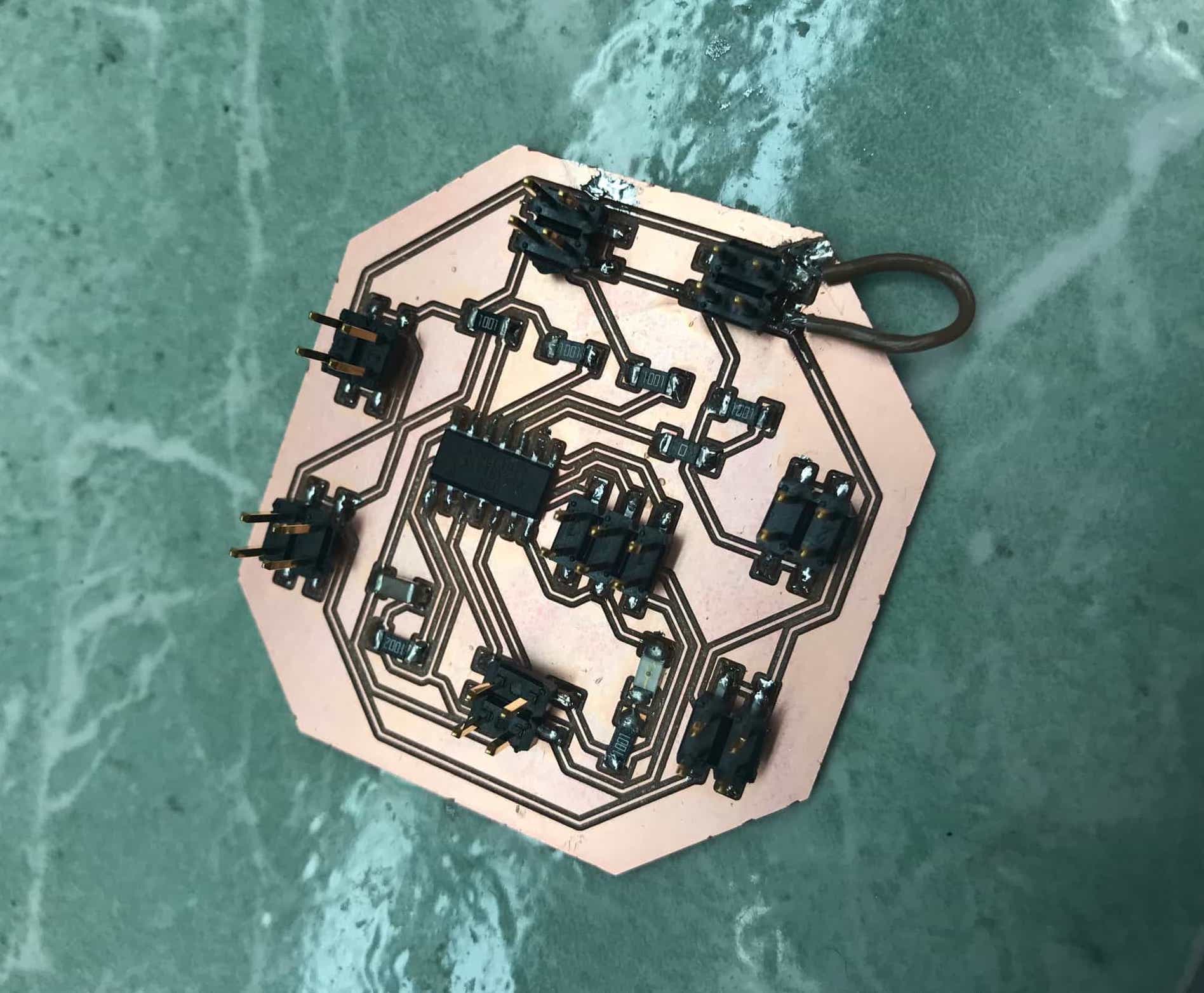
I also finished the design of a capacitive touch sensing board that I would like to incorporate into my project if time allows. This would allow the keyboard to relay to the computer via serial when a key is being pressed, and play the note that corresponds to this key. I referred to Matt Blackshaw's page when designing my board.
Capacitive touch sensing board to be a node in the serial network.
Update 12/15
The big excitement of today was that I thought I killed both USB ports in my laptop. It turned out to be some combination of a questionable programmer and a need to restart my computer, but I was quite worried for a while.
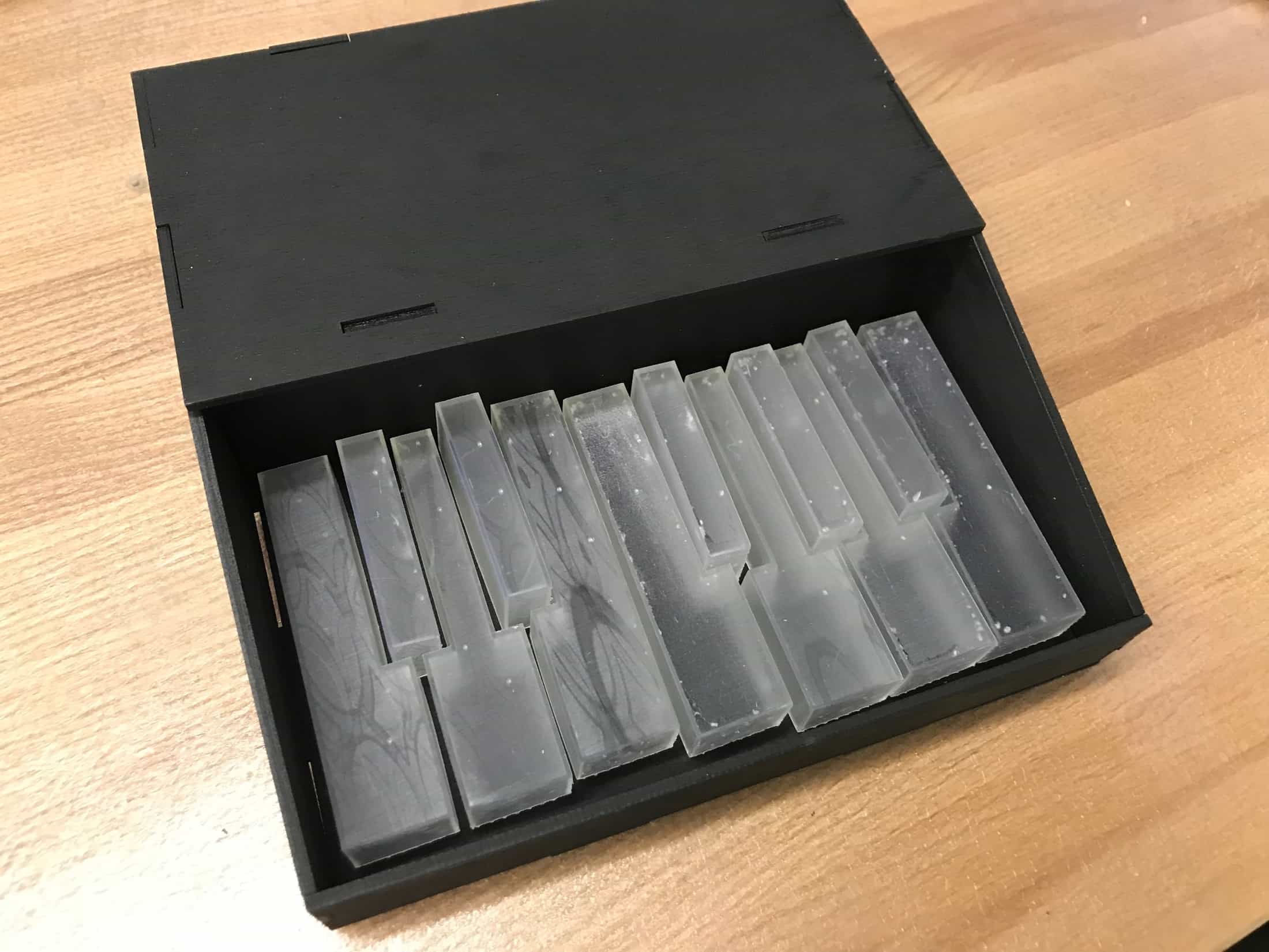
I started the day by going to pick up my print on the Ultimaker. The keys turned out well, but it was a big struggle trying to get the supports out. I also thought I could make the faces of the key thinner so that they would be more transparent. I went back to Rhino to make some changes. I removed the bottom sections at the front and back because they made it hard to remove the support material, and I changed the thicknesses of all the walls of the keys to be 1 mm instead of 2 mm. After these changes, I started a print of five keys. I want a total of 12, but wanted to split the printing up into multiple jobs in case something goes wrong during a print.
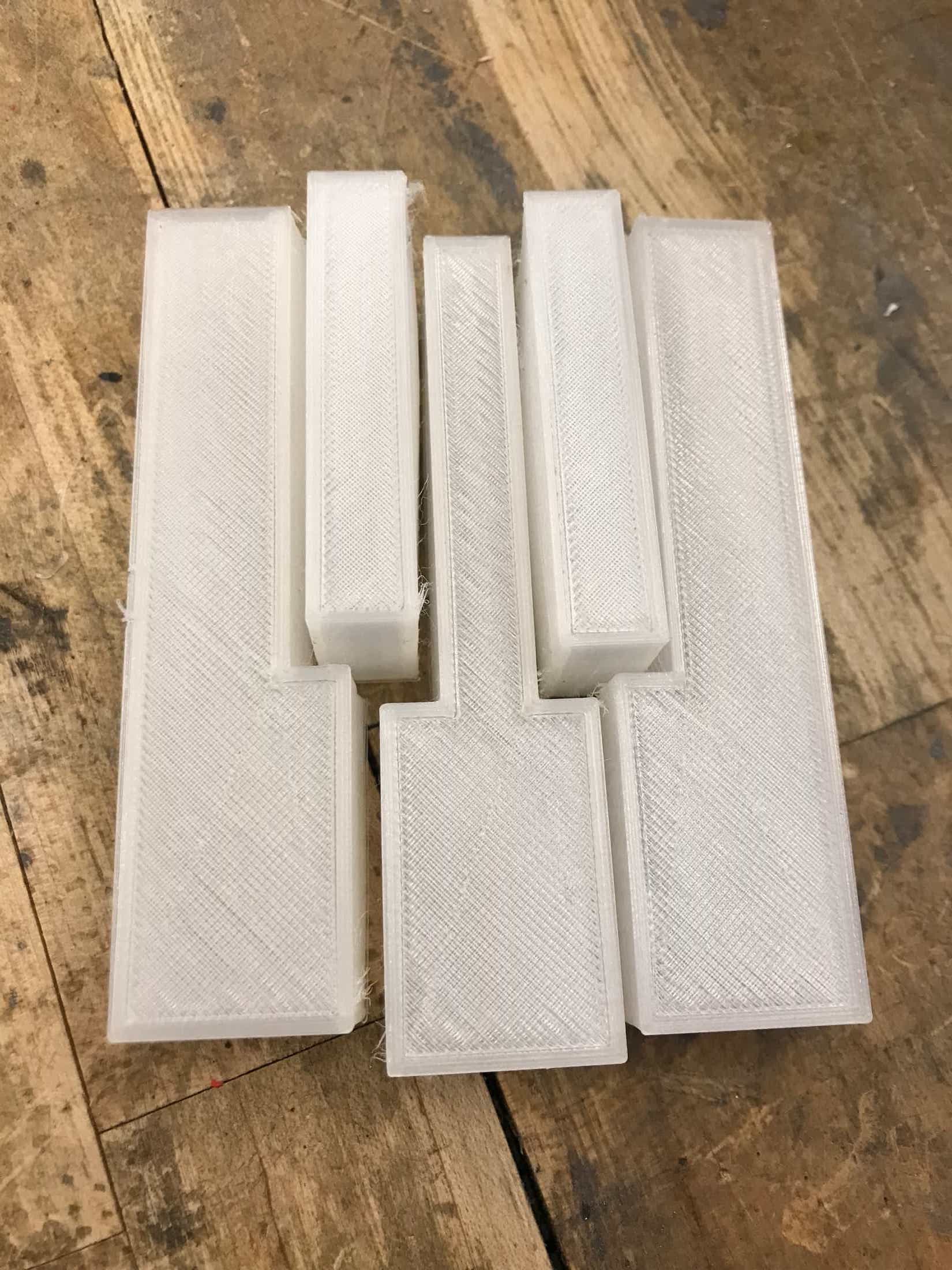
A successful print on the Ultimaker.
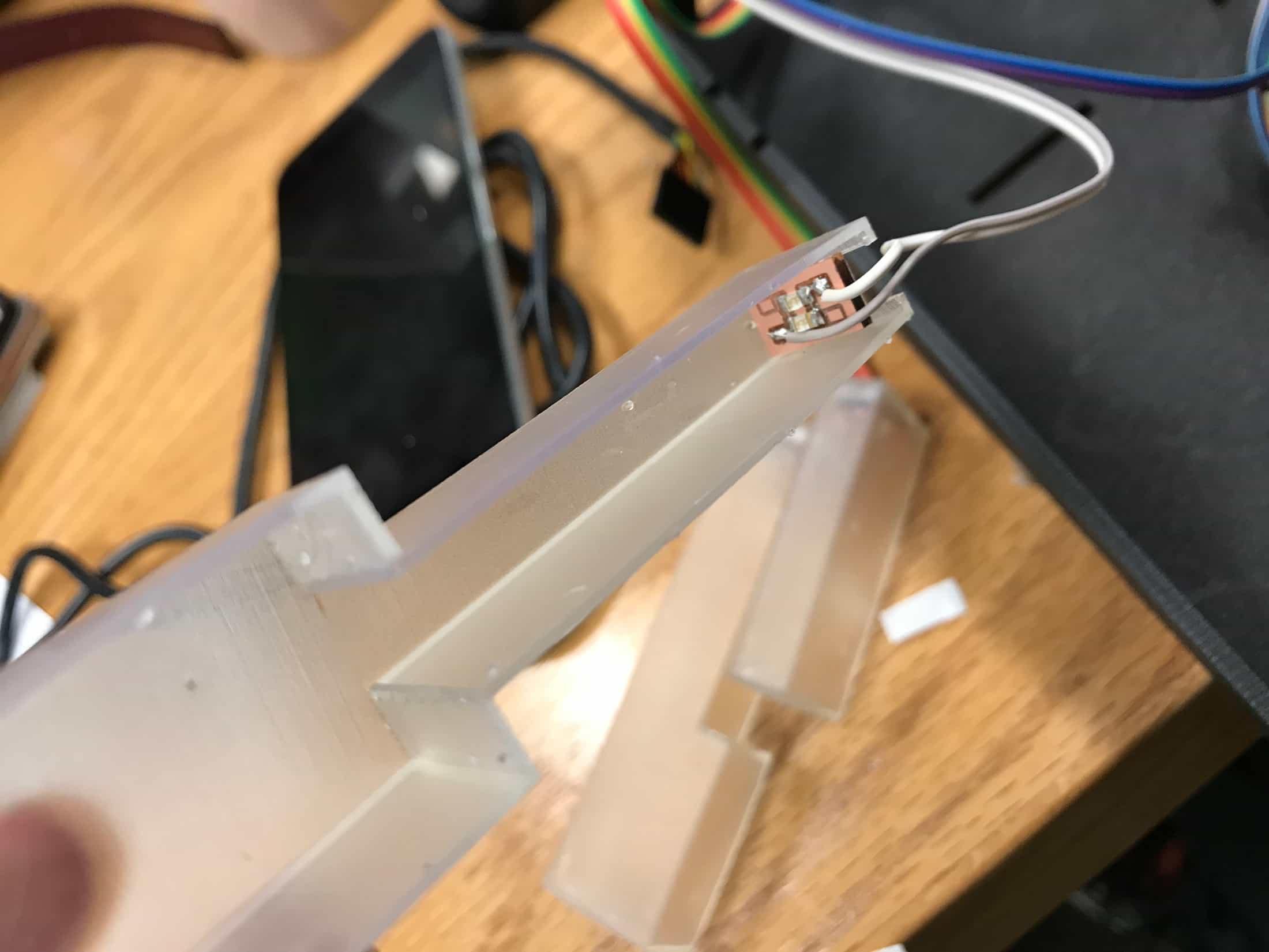
Back in EDS, I wanted to get the external LEDs for within each key set up. I was going with the SMD LEDs because they were much brighter than the through-hole ones in EDS, and I also couldn't find datasheets on the details of the through-hole ones to figure out what resistors I could use. Anyways, I tested turning on an SMD LED under one of the keys, and the light was visible. I thought maybe more LEDs would be more visible, so I made a super tiny board with two LEDs in parallel that I could attach wires to and place in each piano key. I started just by making one to test, but ended up making all twelve mini boards for inside each key.
While I was making these boards, I also milled and stuffed my capacitive sensing board so that I would have that to test. I hooked up the wires from the pin headers to the LED boards for each piano key, and went back to my code because I wanted to be able to tell the board from my computer which LED to turn on. This is where the problems started. I had the programmer connected, but my computer said it wasn't. I swapped the USB ports that the FTDI and programmer were plugged into and basically, the USB port on the right side of my computer wasn't working at all. Apparently it was possible that I had ruined it by connecting/attempting to program a board that was shorted or something like that. I assumed that the USB port was broken and needed a way to program my board, but now I was short a USB port and couldn't connect the programmer and the FTDI to my computer. Grace helped me find an external power supply. But when I tried to use that and program my board with the programmer connected to my one good USB port, the light on the programmer was turned off again (it was previously turning on when in that port), so I thought that I had blown the other USB port too. I'm not entirely sure what happened, but somehow the programmer was bad. When I plugged in a different programmer to the USB port on the left side of my computer, the light came on. The light wasn't on when I plugged it into the right side. But after I restarted my computer, it was working on both sides. Anyways, I was able to reprogram my board and neither USB port in my computer was destroyed, so that was the best case scenario.
I was able to connect all the external LED boards to my main board and program it so that I could turn on specific LEDs by a character id. It worked! It's not perfect though, because for a couple certain LEDs, the LEDs don't shine as bright as they should and the LEDs on another board flash really dimly, which they shouldn't.
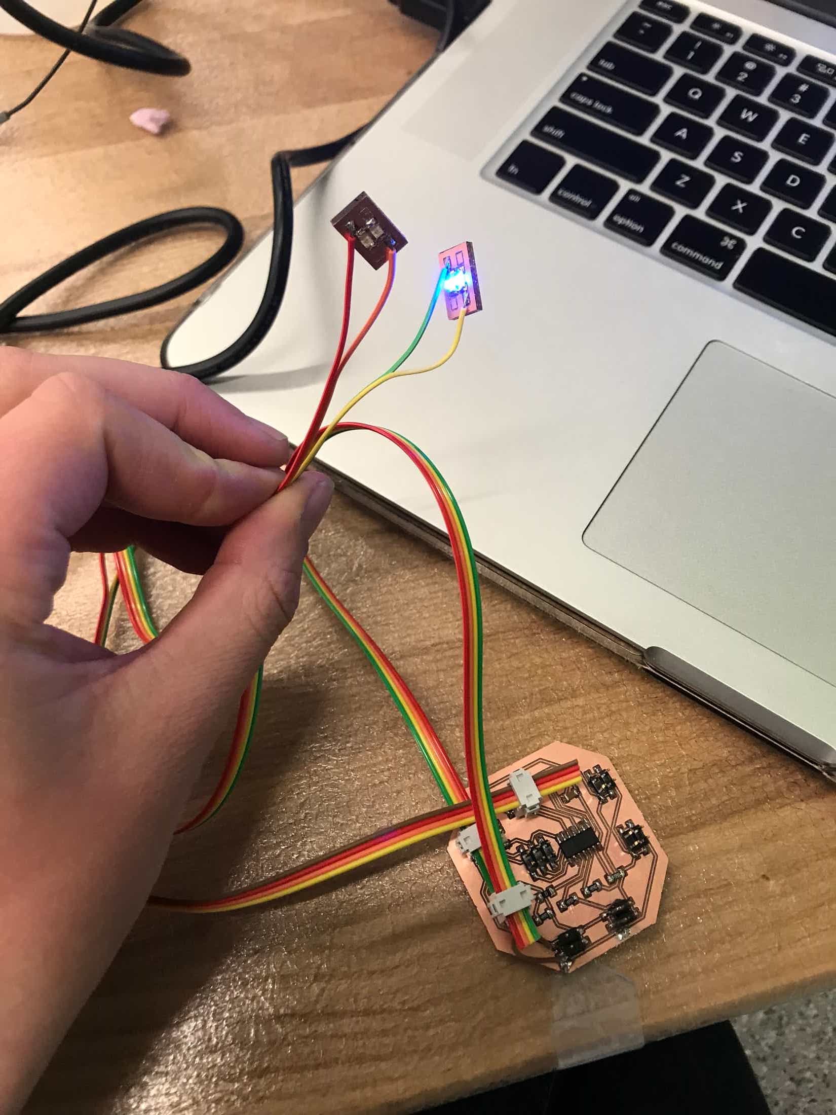
Testing my mini external LED boards.
I picked up my prints from the IDC and they turned out well. The backs of the keys are a little squished up, but I don't think that matters since that part won't be visible. I think the thinner walls was a good idea. I started a print with the seven other keys I need to make the full number of keys I want. I didn't end up machining wax to mold today, and I don't think I will since the 3D printing seems promising.
Update 12/16
The first thing I did today was go to the IDC to check on my final set of 3D prints and it didn't look too good. The keys were about 1/4 finished and on the ground in front of the machine, and there were globs of melted/hardened filament material between the extruder and the grill cover. I emailed Chris from IDC to let him know what had happened, and am still deciding what to do about the rest of the keys. Between the two times I printed on the Ultimaker, I only need three more keys, so I still don't think it's worth machining wax and casting and molding to make the keys.
The broken Ultimaker and my unfinished print.
When I got to EDS, I wanted to test my capacitive touch board. I tried to program it, but got my favorite rc=-1 error. I used a multimeter and checked all my connections and everything seemed fine.
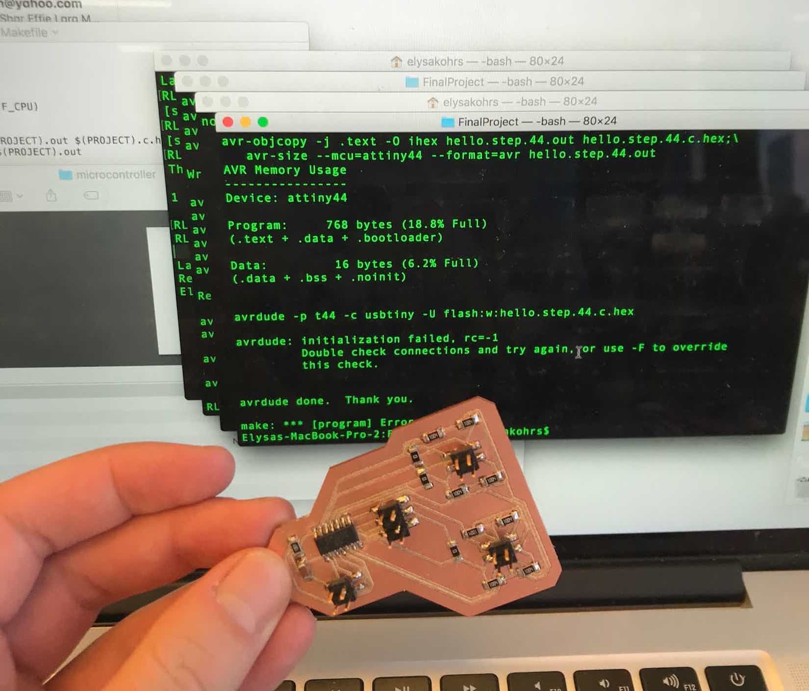
Ugh.
I asked Shirin, and she told me to add a little more solder to the microcontroller pins. I did that, but still couldn't program it. So then I replaced the ATTiny44 on my board, but still couldn't program it. Then Shirin helped me get out the oscilloscope to test what signals my board was getting when I was trying to program it. But my board wasn't seeing anything at all. We wondered if the programmer was bad. I borrowed Max's FabTinyISP and was able to program my board! There are apparently no working programmers in EDS, which is a problem because there are a number of us whose FabTinyISPs don't work. Mine worked when I initially made it, but stopped working sometime early on. I tried to make another a few weeks ago, but wasn't able to program it. I wonder if I was trying to program it with a bad programmer or if my board had the problem. Anyways, I want to have my own programmer but both mills were being used and EDS wasn't going to be open for too much longer so I borrowed Max's a few times for the next hour.
I referred to and combined a couple different C programs to program my capacitive touch board. I looked at Matt Blackshaw's code for his capacitive touch board, and also incorporated the code for serial bus communication. I'm still struggling with it. My board was outputting something, but it was making my bridge board flash constantly, which I didn't want. I couldn't get it so that I was able to see the serial output of the board from screen on my computer. I tried swapping the serial input and serial output pins in my code in case I mixed those up, since I had done that during networking week, but I don't think that's what the problem was.

Setup for testing my capacitive touch board.
Since Shirin was in EDS, I wanted to asked her about my charlieplexing issue where other LEDs were coming on really dimly in addition to the one that is actually supposed to come on. I'm still a little hazy on what's causing it, but it only happens with LEDs that share the same line. She thinks I could fix it by adding a resistor in front of the + side of each LED. We did a quick test of it on one LED and it seemed to solve the problem.
When EDS closed, I worked on parts of the project I could do from home. Chris had gotten back to me since I emailed him about the Ultimaker, and he offered to print my parts on the Form because it also has clear filament. (The Ultimaker is self-serve in the IDC, but Chris himself runs prints for all the other printers). I had to adjust my designs for the Form, because they needed to be thicker for that printer. I sent Chris a huge thank you with the file for the Form printer.
Next, I finally put the time into creating a computer application to interface with my physical keyboard. I used Processing. I had played around with it before, and had serial communication working through Processing between a random sketch and my bridge and LED controller boards. I want someone to be able to add music notes as if creating sheet music, so I started with the horizontal lines. Then I made it so that clicking would add notes to the closest location. Eventually, I got the sketch turning clicks into a series of "notes", which I just stored as integers. Whenever someone clicks, the array of notes updates and the staff and notes are redrawn. Whenever someone presses a key, the music plays the series of notes on the computer. I used the Sound library of Processing to do this.
Version of a Processing sketch.
Update 12/17
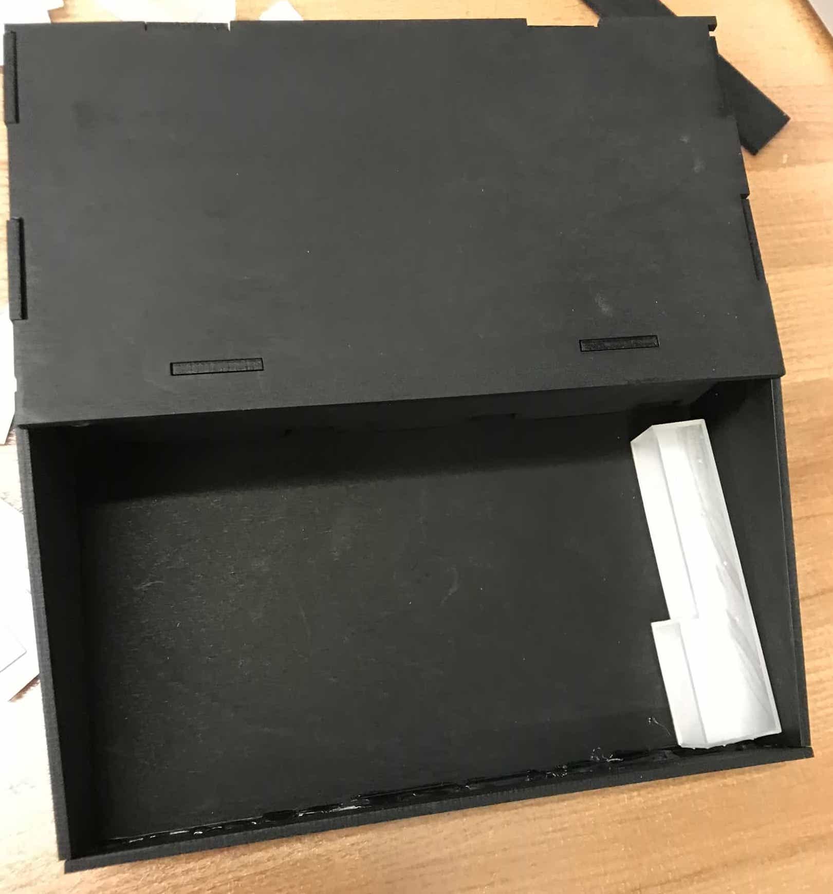
I don't want the physical portion of my project to just be a bunch of loose keys. I want the keys to be arranged in something that looks niceish. I spent Sunday morning designing this housing for the keys, which I am going to laser cut from plywood. It has finger joints for the different parts to fit together. I tried to make it look like a mini piano. I left room for a back section to house the electronics and most of the wires. There are holes in the middle piece of wood for the wires to travel through so that they can pass into the keys. I always think CAD design won't take me that long, but it ends up taking a long time. Creating the joints between the different pieces was the most time-consuming part.
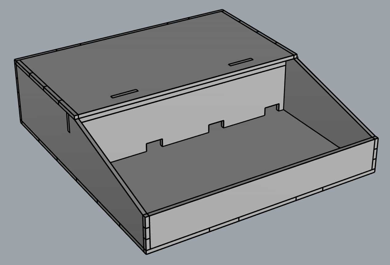
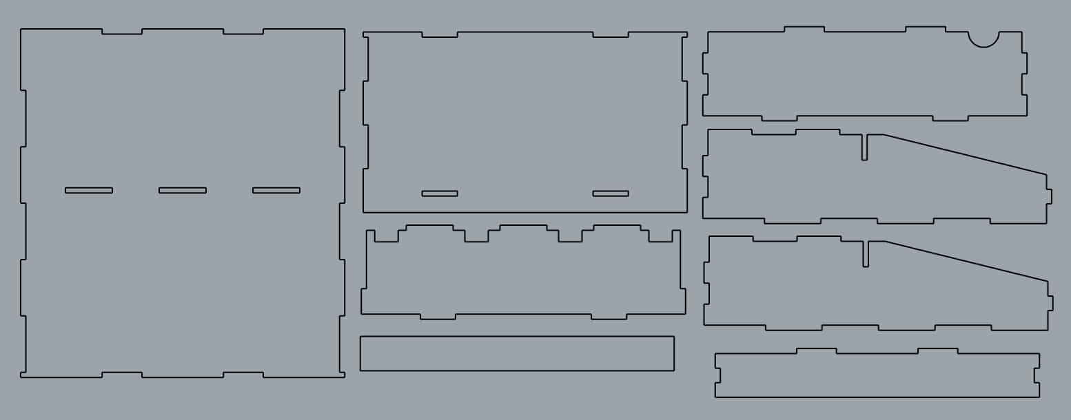
Designs for the piano housing.
When I went to EDS, I first wanted to play a bit more with my capacitive sensing board to see if I could get it outputting values via serial. I made it only attempt to sense one of the eight pins for debugging purposes. I was able to get the board to send messages that I could properly see with screen. However, I could only see messages where I gave the exact string or character in the program. When I tried to relay a variable such as the pin or the step response value, I either saw nothing or saw the diamonds with question marks. Even when I saw nothing, I know that my board was sending something because my FTDI cable flashes upon receiving serial communication. I figured I might have a baudrate issue given that I was seeing weird symbols sometimes. But I tried changing the bit delay in my code but didn't have any success with this solving the serial communication issue. I am curious about whether a baudrate issue would explain the behavior. Why would I be able to perfectly see a message I hard-code into the program but not be able to see a message containing a variable value? I want to ask a TA about this because I am curious about what is going on and really want to get step response to work. However, in the spirit of spiral development and due to the fact that this project is due in two days, I've decided to ditch the touch sensing goal I had. I will finish a complete version of the project with the computer application that triggers LEDs to light before I try to get the capacitive sensing to work.
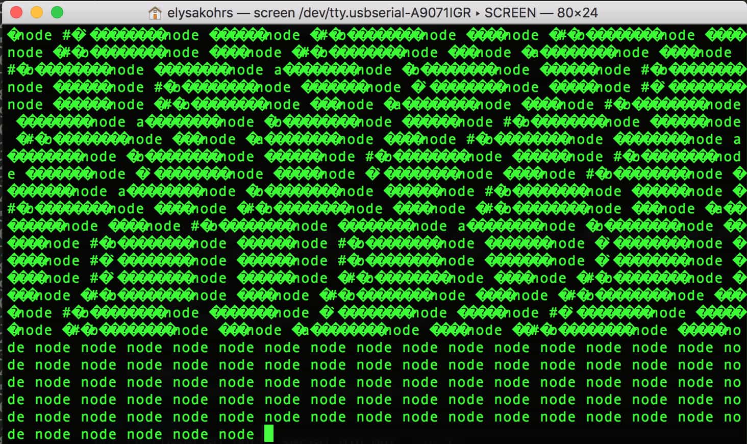
Output I see over serial from my capacitive sensing board. I can't see variable values when I try to send thoe over serial, but can see constant strings/characters.
I really want to have my own programmer because it's a pain to keep borrowing other people's. The Roland was finally free, so I milled a FabTinyISP board. After only using the Othermill for the past few weeks, I forgot how slow the Roland is in comparison. And it was also really finicky...opening the door was causing it to reset completely. We had a putty scraper stuck in the door to prevent us from opening it all the way, but Gavin said that some tiny part they had attached must have come off and put it back in. The first time I milled my traces they didn't cut all the way on one side, so I had to repeat it. Then I gathered the parts and stuffed the board. The only mistake I made was forgetting to check the direction of the diodes, so I had to use the heat gun to take them off and reattach them. Then I was ready to try to program my programmer. I was able to run make flash and make fuses on the first try. My computer was able to recognize my board as a USB device. But I don't know what happened, because when I tried to run make rstdisbl, I got the rc=-1 error. I also couldn't run make flash or make fuses anymore. And then it seemed like neither of my USB ports were working, so I restarted my computer and the ports were fine again, but I still couldn't run make rstdisbl. I tested to make sure the programmer I was using (either Robert's or Natalie's) was still working, and it was because I was able to reprogram my LED controller board. Anyways, I wasn't able to successfully make my own programmer.
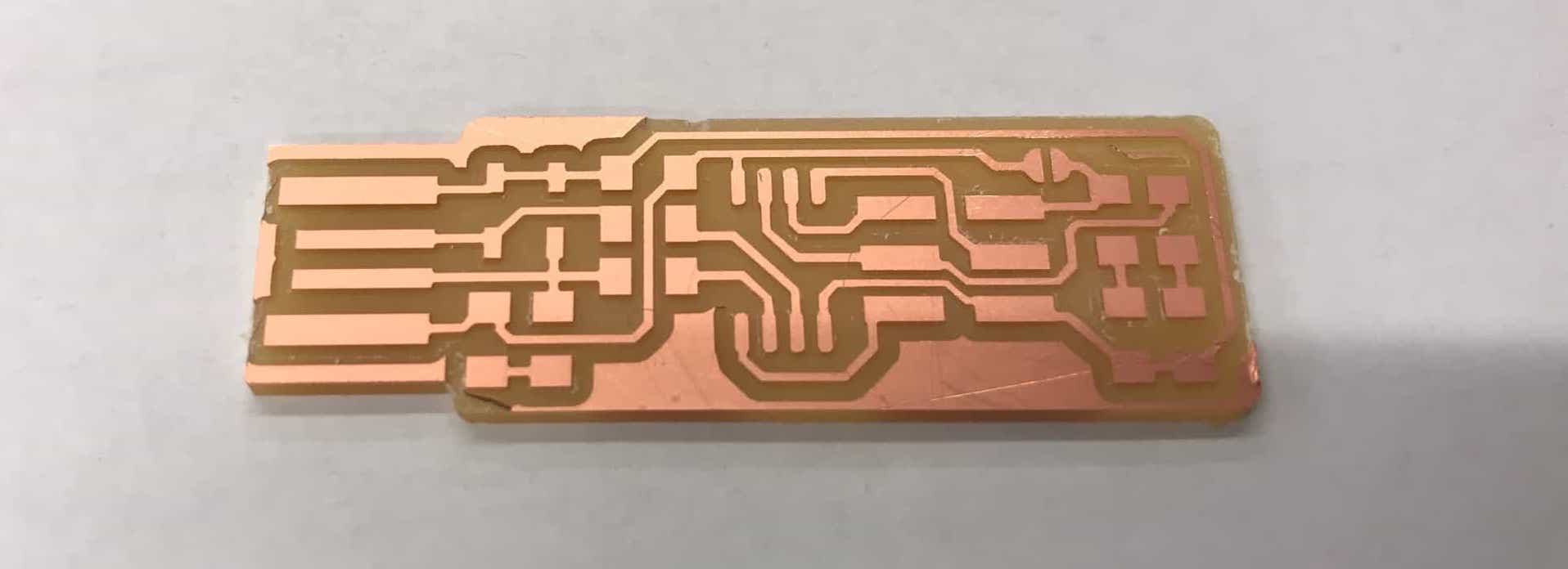
I tried but failed to make my own programmer.
I had designed the piano casing in the morning but wanted to cut it from cardboard to see if everything fit and if I need to make any changes before laser cutting it from the plywood. I cut the pieces from cardboard. The cardboard is slightly thicker than the plywood, but I just flattened a couple of the cardboard joints to make things fit. The first time I cut the sides, I accidentally forgot to include the holes in them that the panel hiding the electronics is supposed to fit into. I recut the two sides and then connected everything, and filled it with the assorted 3D printed keys I have already. Everything fit pretty nicely. I want to make the back section for the electronics a little bigger because my wires are unnecessarily long and awkward and I have a lot of them connecting to the LEDs. But overall I think the design of the piano housing is pretty good. I'll laser cut it from plywood and probably spray paint it black tomorrow.
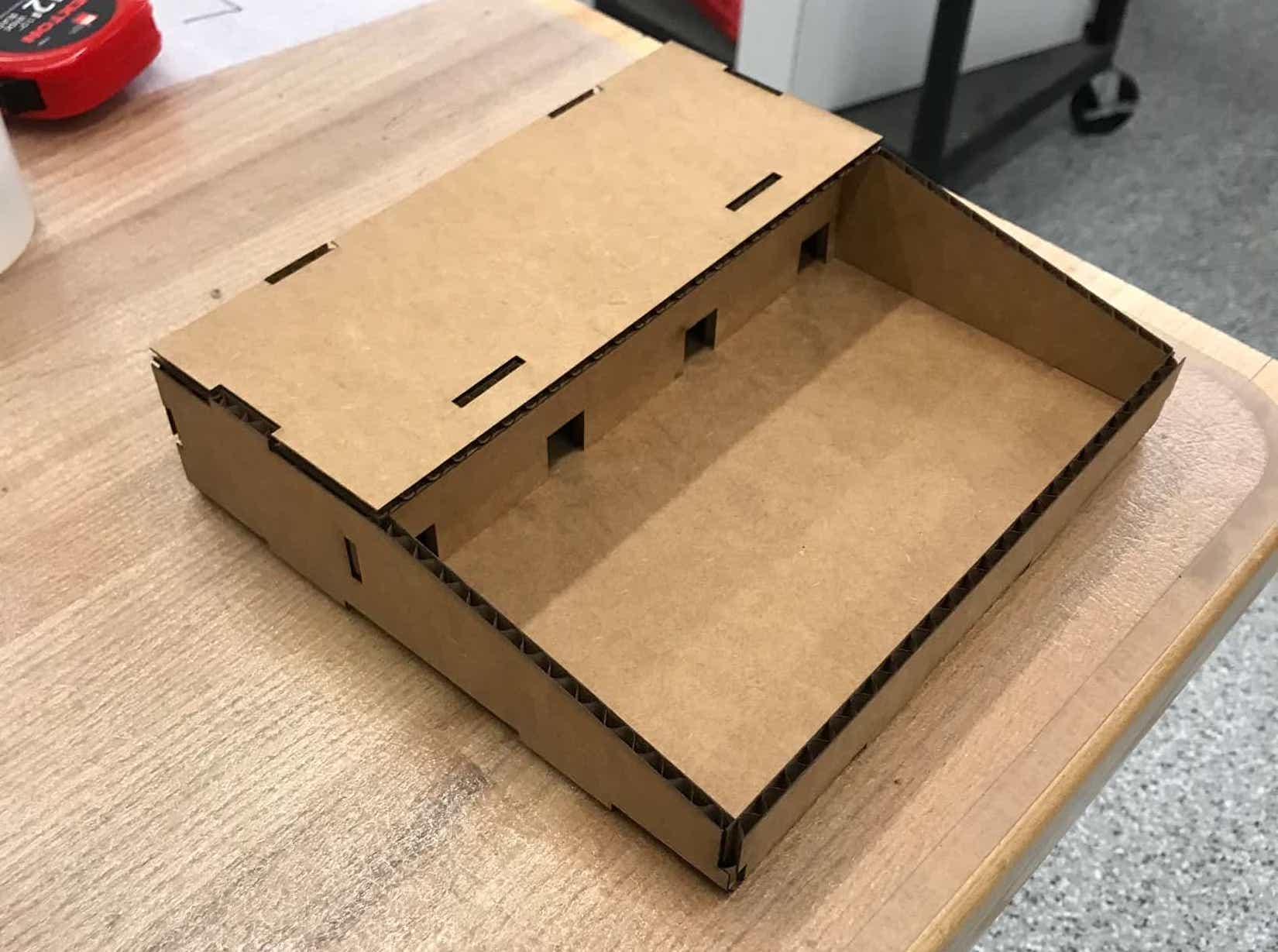
It looks like a mini piano.
A working prototype.
I had an earlier Processing sketch communicating via serial to one of my boards, but I wanted to connect my newest Processing application to my LED controller board. I just had to make a couple adjustments for timing, but I got it working. The placement of keys in the computer interface controls both the sound that comes back through the computer and which LEDs light up.
My Processing sketch lights up LEDs.
Update 12/18
It's the final day! I spent an hour or so in the morning modifying my Rhino designs for the piano housing. I wanted increase the space for my electronics and make it a little taller. After I made those changes (which took longer than I wanted), I cut the new pieces from cardboard to test. They seemed good, so I cut them from plywood to use for my final. I didn't account for kerf on purpose because I want to spray paint the pieces. As expected, they didn't press fit togehter because the fit was too loose.
I picked up my 3D printed keys from the IDC mid-day. Chris is my hero. He printed all twelve keys on the Form and they turned out really well. He had them soaking in alcohol to try to remove some of the stickiness, and then showed me how to use the UV curing machine. For a project for another class, I had printed one thing on the Form with clear filament, and I scratched the surface really badly while trying to remove the supports. So I tried to be really careful with removing the supports from the keys, and I think I did a pretty good job this time. There are definitely some nicks and imperfections on the keys (mainly on the inside), but overall I really like how they turned out.
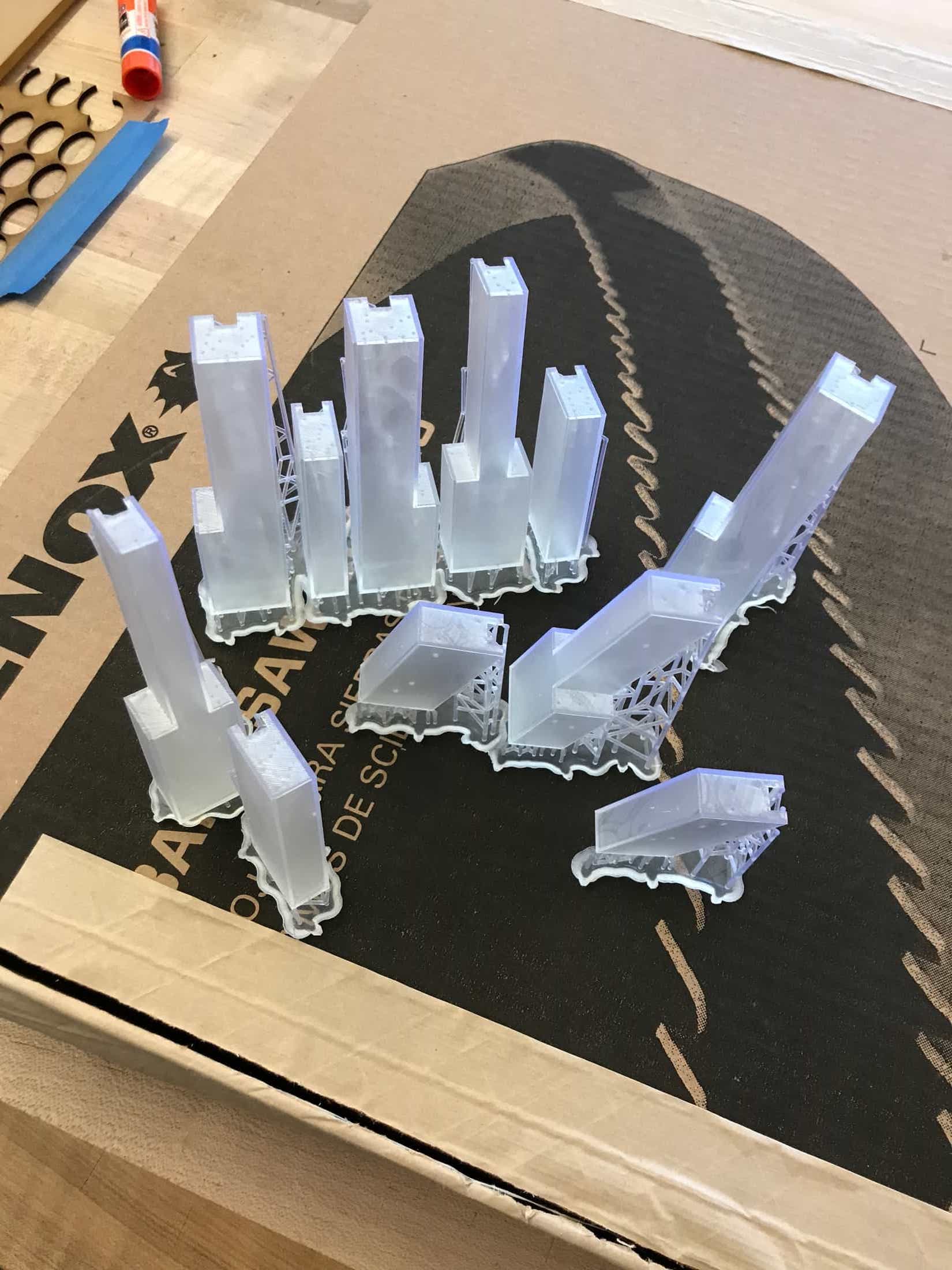
Piano keys, printed on a Form 2 printer.
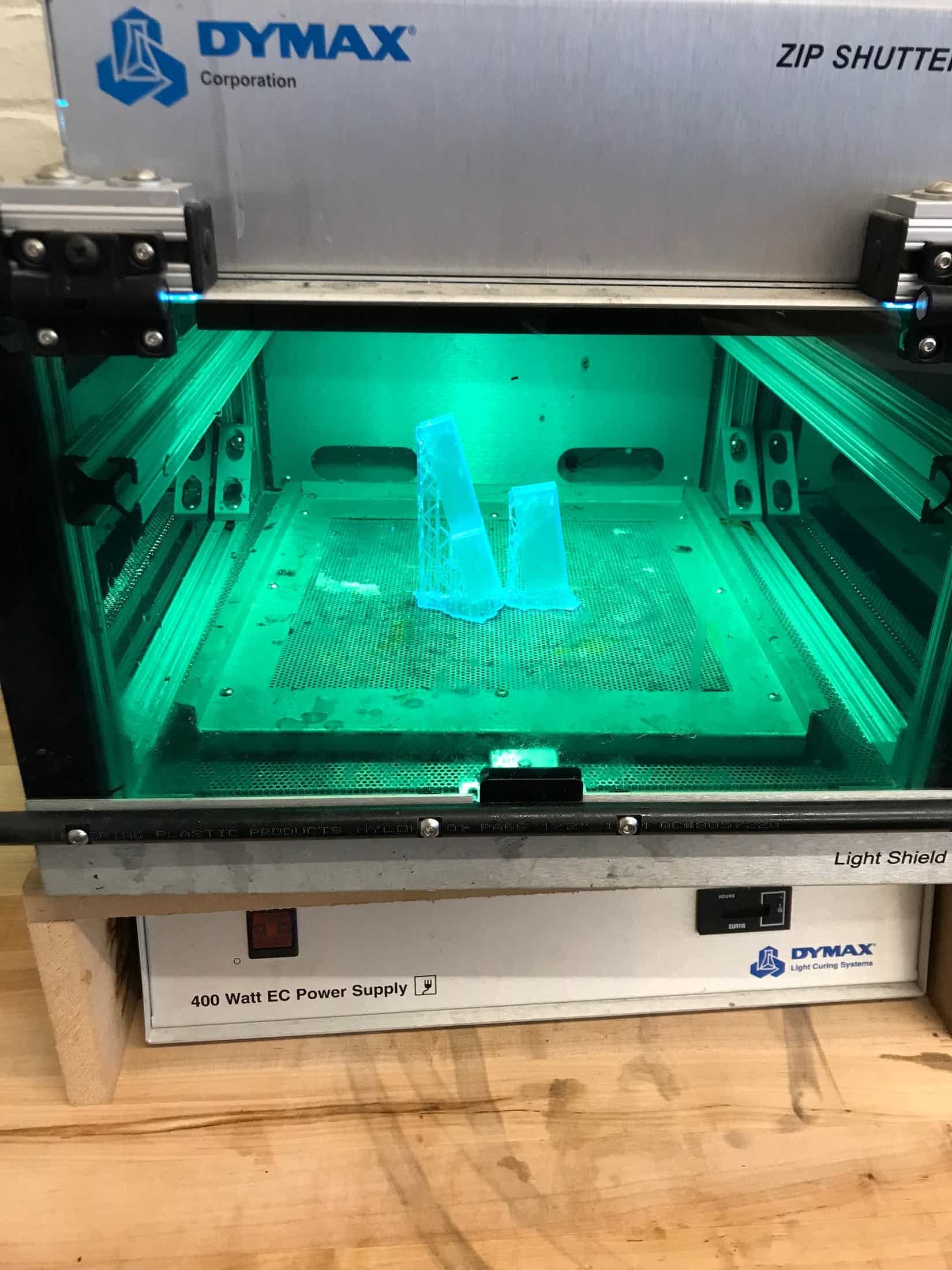
UV curing the keys.
I went to the fume hood in the architecture shop to spray paint the pieces of my piano box. I did two coats, and a couple extra fixes in certain areas. When I took the pieces back to EDS to attach them together, I realized that I forgot to make a hole in the back upright piece. I laser cut that piece again and journeyed to Building 3 to spray paint it. Once I had that piece, I started fitting together the box. The spray paint hadn't added enough thickness to the wood for the pieces to press-fit together snugly. I added hot glue to just a couple areas (mainly beneath the area that gets hidden when the top is on). The back piece, upright middle piece, and top are removable to allow for fixing of electronics.
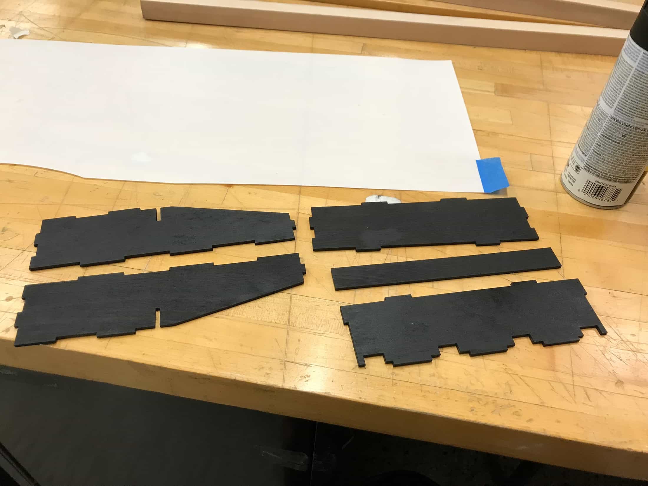
Spray-painted pieces to make the piano housing.
Hot gluing a couple panels together.
It's a mini piano.
I started securing the LEDs into the keys. I'm using the 12 mini boards I made which each have two LEDs and have a jumper wire soldered to their anode side and another to their cathode side. I used double-sided tape to attach each mini LED board to the back of each key on its inside. This process was actually a pain and took a while.
Securing the little LED boards into my piano keys.
Electronics and physical parts coming together.
The piano keys are pretty clear, and when they're placed directly on the black painted wood, they aren't as noticeable as I want them to be. The black also brings out the imperfections in the keys more. I laser-cut a base the exact shape and size of each key from some white chipboard I found in the architecture scrap materials area. I used double-sided tape to attach each base to its 3D printed key.
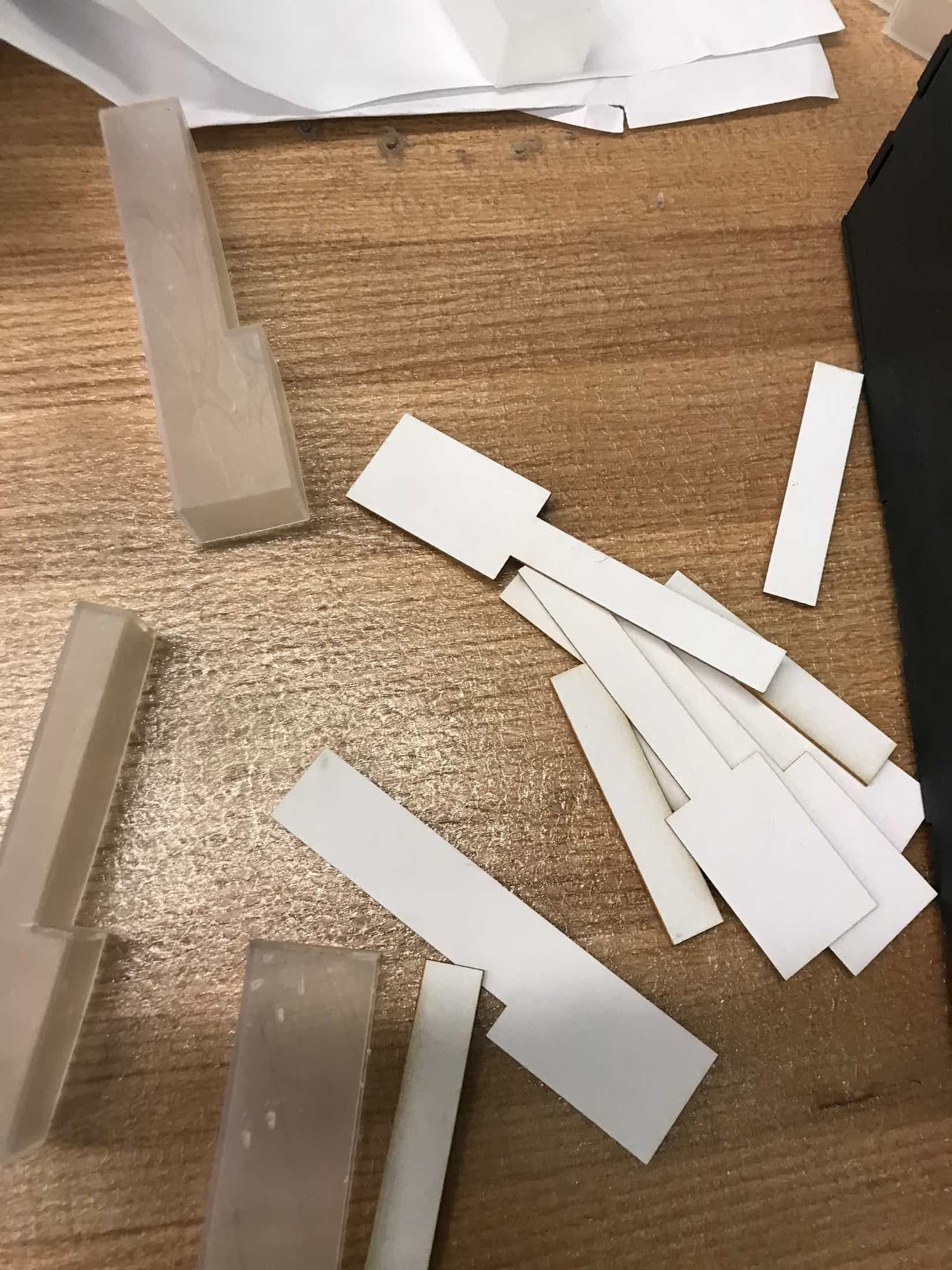
I made bottoms for each key.
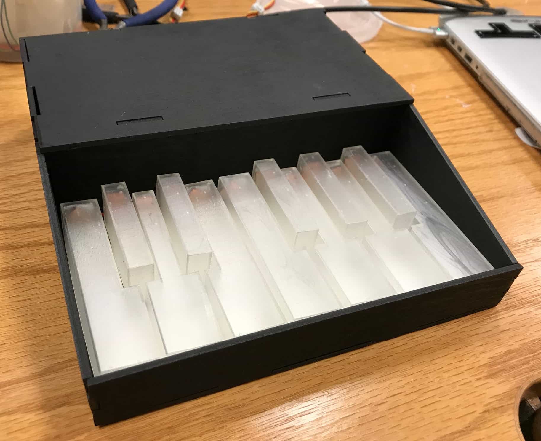
It looks a lot better when the keys have the white base.
At this point, I had a project that looked like a piano and worked when connected to my computer. The keys weren't straight though, because the wires skewed them in certain directions.
A piano with lots of crooked keys.
I added double-sided tape to the bottom of each key to attach it to the wood. At some point during this process, I broke things. Instead of one LED lighting up when I pressed a key, for a bunch of the key ids, two keys would light up. And then for '8' and '9', no keys lit up. I'm not exactly sure what happened, but I am guessing that I created a short between two of the four lines I'm using for charlieplexing. For example, if L2 and L3 were shorted, then the LED from L2 to L3 wouldn't light up at all and neither would the LED from L3 to L2. However, I couldn't find the short so I continued taping keys to the base. After I had them all attached, I tested with screen again and the problem was fixed. Hooray for magical fixes!
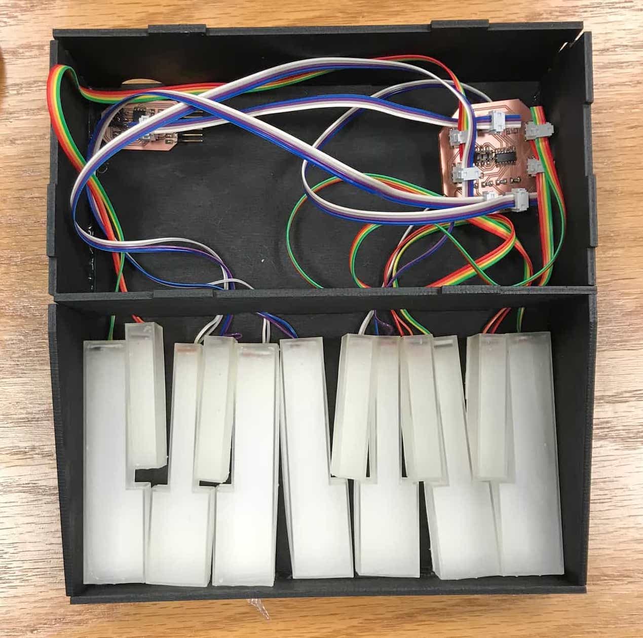
I was pretty much done at this point. I fiddled around with passing wires through the holes I had made in the middle piece of wood and with arranging the electronics in the back area. Then I put the top on to hide the electronics and took a few pictures and a video of it working.
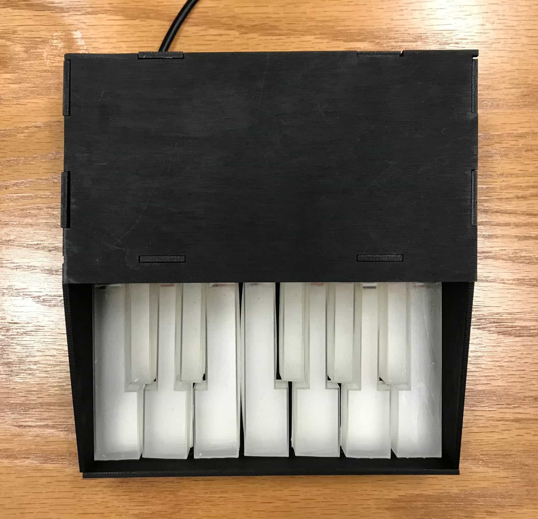
Looking pretty finished.
Woohoo I made a thing that does the thing I want it to!