Make Something Big!
Yes! Finally! I've been looking forwrad to this week for a while now. I have two goals for this week,
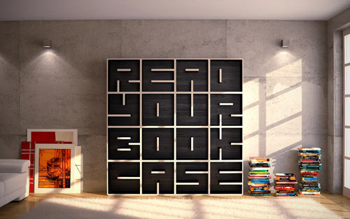 I strated by looking for inspiration online, and as soon as I saw this, I knew what I wanted to make. It was perfect!
I do need a book shelf in my appartment, this does look pretty cool and artistic and finally, it is BIG.
I strated by looking for inspiration online, and as soon as I saw this, I knew what I wanted to make. It was perfect!
I do need a book shelf in my appartment, this does look pretty cool and artistic and finally, it is BIG.Looking at this picture for a while, I thought I would like it to be modular, i.e. each letter would be an individual "box" that could be stacked at angles or even separated. A couple of quick calcualations (and simply intuition) showed that I would at best be able to fit 4 letters.
Designing the files on SolidWorks
SolidWorks is my go-to CAD software due to familiarty and the ease of parametric design. This was particularly important because when I started designing the parts, I did not know what tool sizes we had available for our use. The tool diameter is espeically important since, you can't really have sharp internal corners, you have to "dog-bone" or add slots that allow your parts to sit squarely when assembled. I set up the diamter of such slots in a parametric manner linked to the tool diameter as seen in the figure below.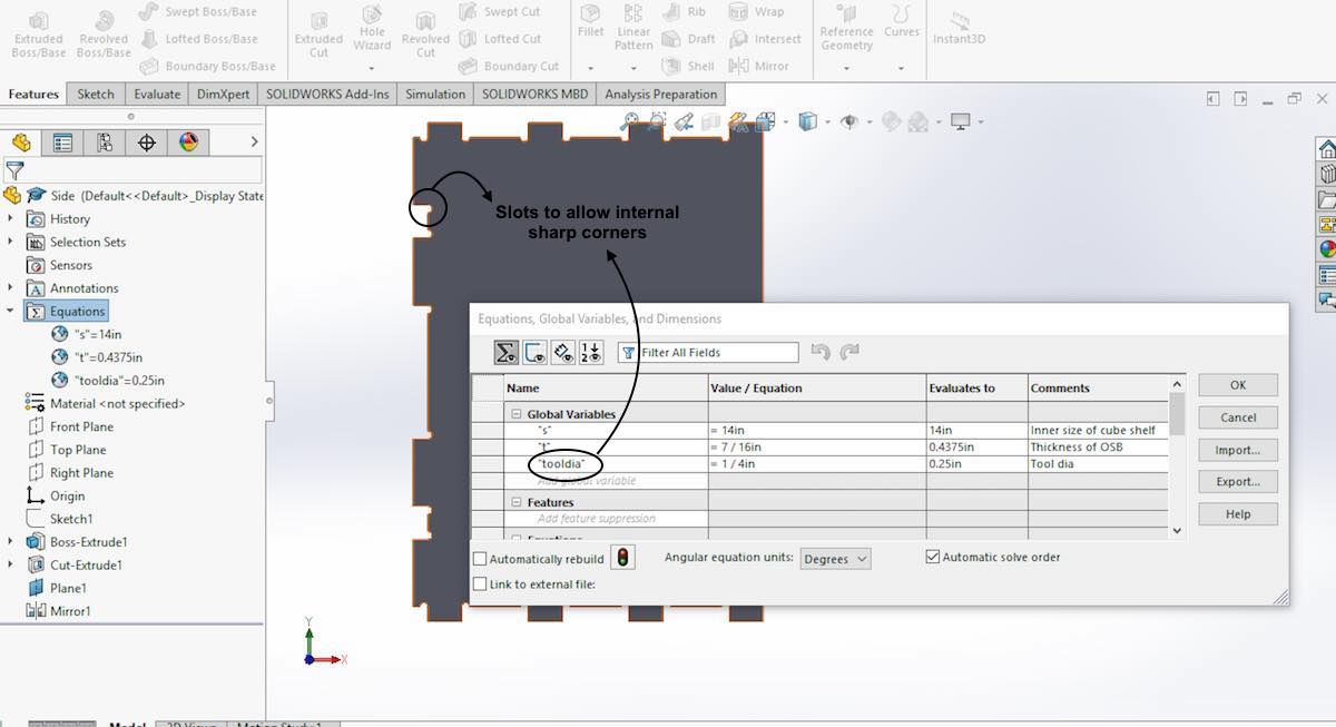
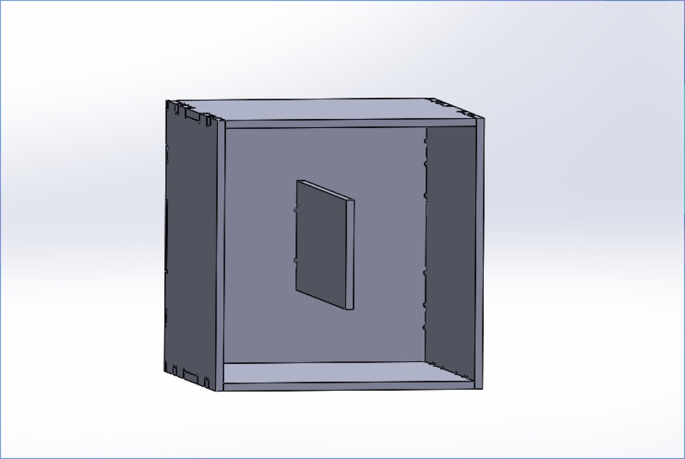
I similarly designed all my parts and fit them together in an assembly to see if there are any issues that might come up. The assembly looked fine and it was ready to go! The figure below shows what the "O" box would look like.
Creating drawings for the CNC
With the individual parts ready and the assembly done to check for any faults, I was ready to create the inputs to the CNC router. If you are using SolidWorks, the easiest way to get clean DXF or AI files are to create a SW Drawing and then export that in the required format. The process looks something like this:- Create parts as requried
- Create an assembly and arrange parts as required
- Create a drawing from the assembly. make sure the scale on the drawing sheet is set to 1:1
- Use the Save As option to exprot the drawing in the desired format.
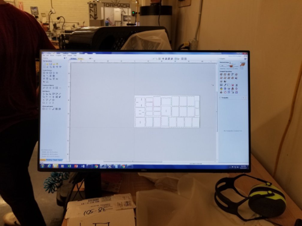
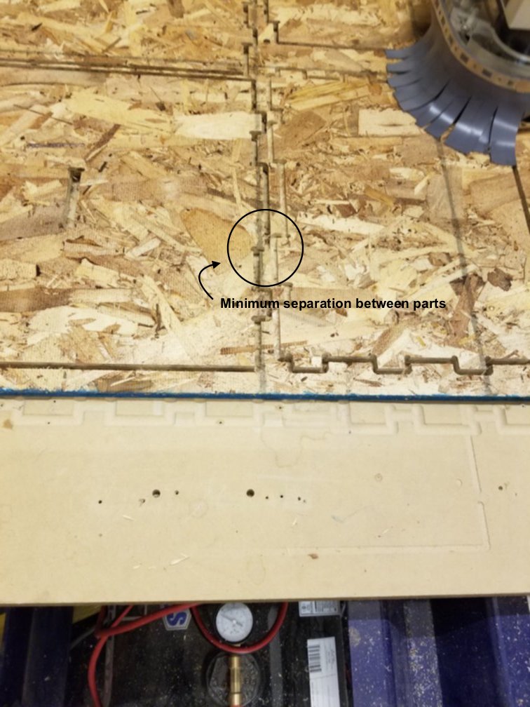
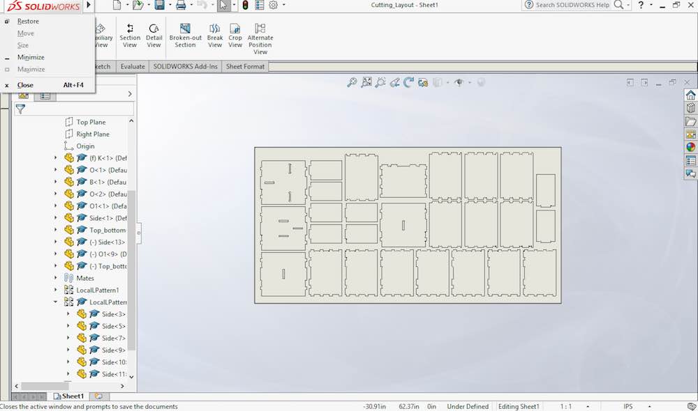 The figure here shows the drawing where I have arranged all the parts to be cut out. A key thing to remember at this stage is the minimum spacing between parts.
Theoretically you could place your parts apart by exactly 1 tool diameter, which should allow you to use a single pass to cut two pieces. However if you wanted to play it safe at least 3 tool diameters would ensure that you have two separate cuts.
The figure here shows the drawing where I have arranged all the parts to be cut out. A key thing to remember at this stage is the minimum spacing between parts.
Theoretically you could place your parts apart by exactly 1 tool diameter, which should allow you to use a single pass to cut two pieces. However if you wanted to play it safe at least 3 tool diameters would ensure that you have two separate cuts.
Cutting the parts
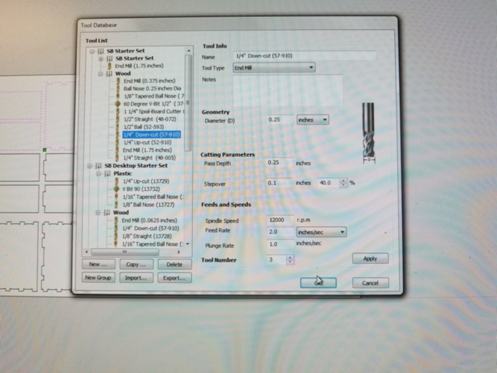
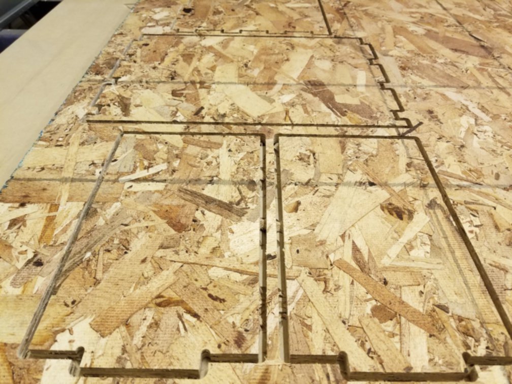
With the drawings exported in DXF, we are ready to cut the parts using the ShopBot in the International Design Centre (IDC). The below series of pictures shows the process from setting up the tool path, setting the feeds and speeds, makign sure the tool is in good condition and the cutting.Since I wanted to maximize the use of the 4'x8' OSB we had, fixturing the board was non-trivial. We split the job into three parts going from top to bottom in the orientation shown in the figures here. After each job was done, we were able carefully see where we had space to put down fixturing screws. This seemed to work well (for the most part).

Finishing
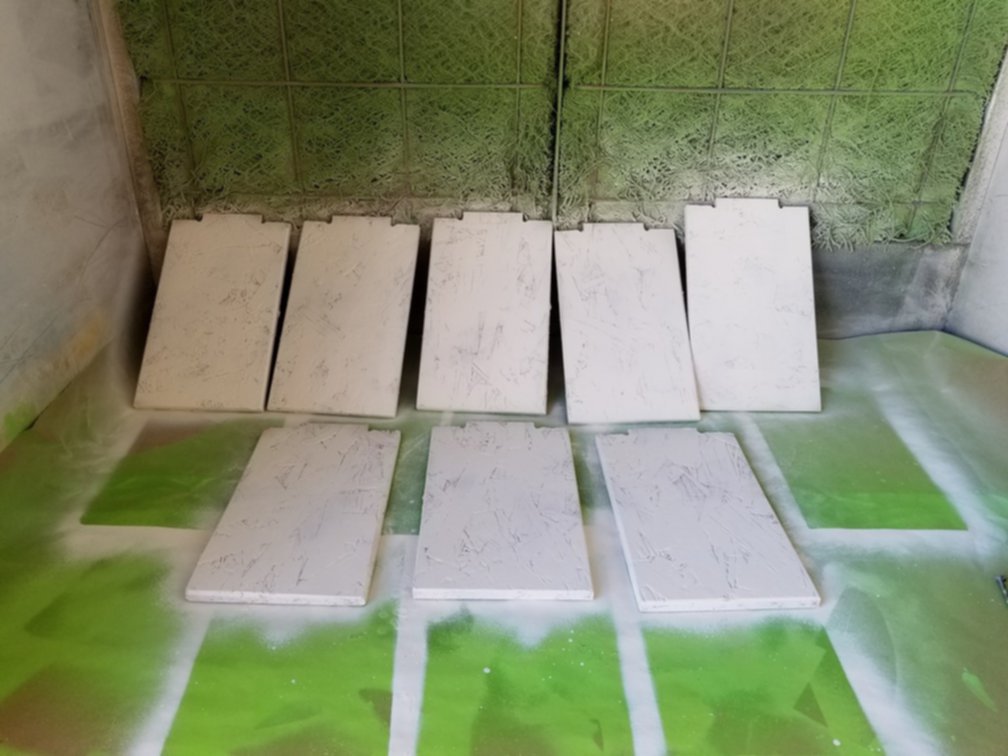
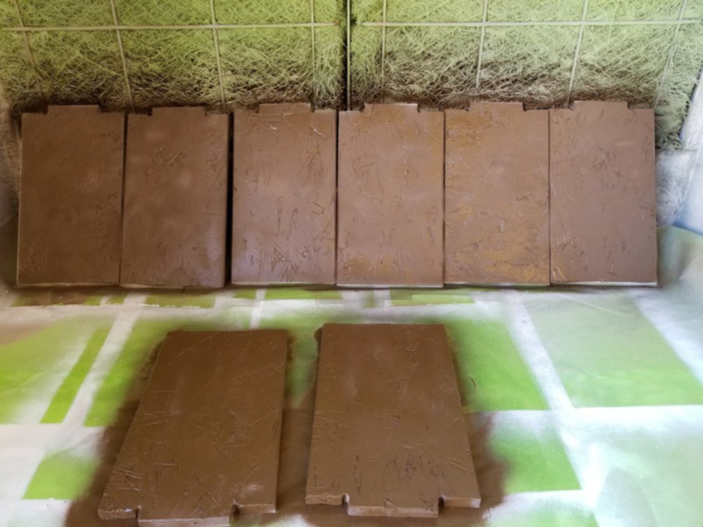
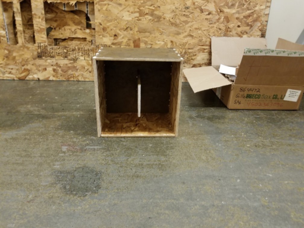
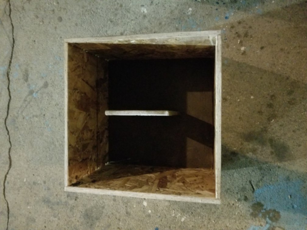
Once all the parts were cut out, I used a combination of the orbital sander, belt sander and a tiny sanding bit on a Dremel tool to clean up the parts. Then after consulting the local hardware and art store (Phils Hardware on Mass Ave and Blick) I got some white sealer/primer and some spray paint to finish the parts.At the time of pushing this I have only managed to fully paint one block, I choose the "O" block for simplicity (only one internal part). The picture below tell the story:
Update
Finally I used the weekend to paint this and put in my appartment! My flat mates are really happy :D
