Putting code in ATTiny 44s
So as it turns out the double sided board that I had desinged couple weeks ago doesn't really work. I decided to redesign the board (single sided now) and make it as simple as possible to avoid multiple points of failure.
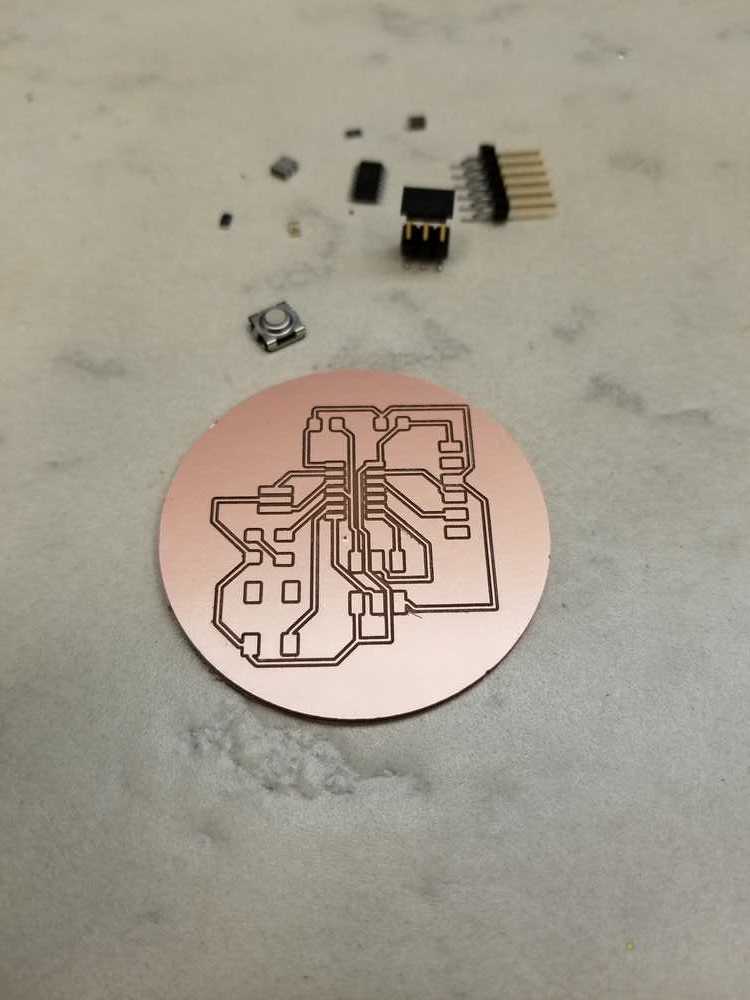
 Here is the finished board that I made this week. I wanted it to still be special so I made it circular. In the process I learnt that the otherMill software,
really doesn't like circles. However it is ok with arcs. So naturally I made an arc that was almost a complete circle and then just drew a straigt line.
And voila that worked.
Here is the finished board that I made this week. I wanted it to still be special so I made it circular. In the process I learnt that the otherMill software,
really doesn't like circles. However it is ok with arcs. So naturally I made an arc that was almost a complete circle and then just drew a straigt line.
And voila that worked.
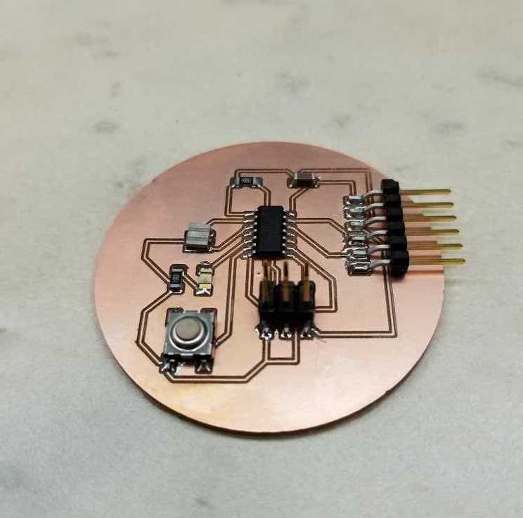
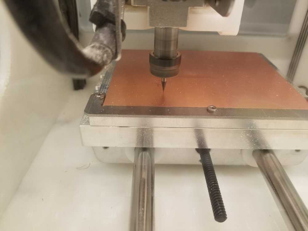
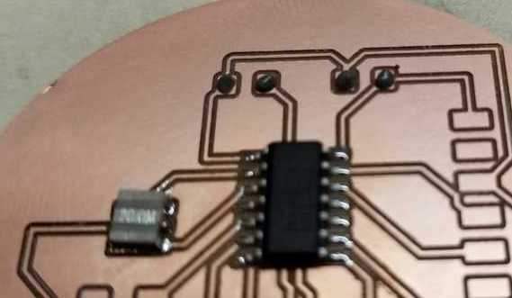
Once that was ready I populated the board, this time using solder paste. That stuff works like magic! This was the cleanest board I'd made so far! The following set of images show the process from milling to a fully populated board.
Programming the board
Now that I had a board, it was time to see if it was actually working. Starting with Neil's code, I set the fuses and it just wouldn't work. Kept geting the rc=-1 issue over and over again. Going through Ben's useful checklist on the class website (reproduced here for posterity), I found that there was a tiny shard of copper that was shorting two traces that were really close together and only detected because Ben used a mutlimeter while trying to trouble shoot the problem.
Ben's Checklist for rc=-1
Check the following:
If all else fails, mill a new board.
- Programming cable is oriented correctly.
- Board is milled correctly (traces are properly isolated).
- No shorts between power and/or data lines.
- No open circuits between t44 pins and corresponding connector pins.
- Solder joints are in good condition.
- No unintended solder bridges between adjacent pins / traces.
- t44 is oriented correctly on board (check pin 1 indicator).
- Required clock source is present on board (depending on how you set fuses) and in good condition.
- No swapped data signals. (For instance, verify that MOSI goes to MOSI and MISO goes to MISO.)
- Programmer is in good condition (does it talk to a known-good board?).
- Computer is in good condition (does switching computers produce a different result?).
Finally my fuses were set! :D
dhcp-18-40-99-243:Trial Prashanth$ sudo make -f hello.ftdi.44.echo.c.make program-usbtiny-fuses
Password:
avr-objcopy -O ihex hello.ftdi.44.echo.out hello.ftdi.44.echo.c.hex;\
     avr-size --mcu=attiny44 --format=avr hello.ftdi.44.echo.out
AVR Memory Usage
----------------
Device: attiny44

Program:     758 bytes (18.5% Full)
(.text + .data + .bootloader)

Data:         64 bytes (25.0% Full)
(.data + .bss + .noinit)


avrdude -p t44 -P usb -c usbtiny -U lfuse:w:0x5E:m

avrdude: AVR device initialized and ready to accept instructions

Reading | ################################################## | 100% 0.01s

avrdude: Device signature = 0x1e9207 (probably t44)
avrdude: reading input file "0x5E"
avrdude: writing lfuse (1 bytes):

Writing | ################################################## | 100% 0.01s

avrdude: 1 bytes of lfuse written
avrdude: verifying lfuse memory against 0x5E:
avrdude: load data lfuse data from input file 0x5E:
avrdude: input file 0x5E contains 1 bytes
avrdude: reading on-chip lfuse data:

Reading | ################################################## | 100% 0.00s

avrdude: verifying ...
avrdude: 1 bytes of lfuse verified

avrdude: safemode: Fuses OK (E:FF, H:DF, L:5E)

avrdude done.  Thank you.
Making the LED flash
Once the fuses were set and I knew the board was ready to accept code, I decided to go the AVR-GCC, avrdude route and modified some code from this wonderful page that Rob has in the tutorial page.Here is the modified code:
// Shamelessly copied and modifed from Rob Hart, (since I had no idea what I was doing) who...
//"Shamelessly copied and mofied from Neil Gershenfeld's code by Rob Hart for purposes of instruction."
//
//
// Button  PA7 (physically on pin 6 of attiny44).
// LED     PB2 (physically on pin 5 of attiny44).
#include

//----------------------------
//Define useful functions here
//----------------------------

#define output(directions,pin) (directions |= pin) // set port direction for output
#define input(directions,pin) (directions &= (~pin)) // set port direction for input
#define set(port,pin) (port |= pin) // set port pin
#define clear(port,pin) (port &= (~pin)) // clear port pin
#define pin_test(pins,pin) (pins & pin) // test for port pin
#define bit_test(byte,bit) (byte & (1 << bit)) // test for bit set

#define input_port PORTA		// The button is on port A
#define input_direction DDRA	//  DDRA defines input/output for port A
#define input_pin (1 << PA7)	//  The button is on pin 6 of port A
#define input_pins PINA			//  PINA is the register that is read to detect input high or low.
#define output_port PORTB		//  port B will be used for the LED
#define output_direction DDRB	//
#define output_pin (1 << PB2)


//----------------------------
//      Main program
//----------------------------

int main(void) {
   //
   // main
   //

   // initialize pins
   //
   output(output_direction, output_pin);
   set(input_port, input_pin); // turn on pull-up
   input(input_direction, input_pin);
   //
   // main loop
   //
   while (1) {
      //
      //
      //
      if (pin_test(input_pins,input_pin))
      	clear(output_port,output_pin);
	  else
		  set(output_port,output_pin);
      //
      // wait for button up
      //

      }
   }
Here is a short video of the LED responding to the input!