In the past couple of years I've gained an interest in soft robotics, and I'm working for a lab that designs amazing soft robots. However, before this class I had never made a soft robot myself. Soft robotics is the field that deals with robots with highly compliant materials. They are often used to grasp objects that are delicate or have intricate shapes. The molding and casting week (Week 7) was an opportunity for me to start exploring the fabrication techniques.
The motion of soft bending actuators comes from a hybrid design of extensible (compliant silicone, ballons, stretchable fabric) and inextensible materials (tougher or thicker layer of silicone, non stretchable fabric, fibres), allowing the robot to only stretch or bend in a certain direction.
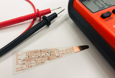
The soft robot needs an input to know when to actuate and a pump for inflation. During the input and output weeks (Week 8 and 9) I designed boards for a capacitance sensor and a pump actuation, and connected the two.
Part of the goal for my final project was to incorporate electronics into the finger, to avoid the electronics being dangling pieces attached to it, as well as to provide myself with an extra challenge. In the first electronics assignment (Week 2) I made a flexible circuit board of acetate. When incorporated in a soft robot, the acetate will perform as an inextensible component and determine the robot's motion.
Clear acetate sheet(s) Copper tape Electronic components Pump (12V) 12V power supply PLA for 3d prints or wax to mill Ecoflex 00-30 Dragon Skin 30 Mold release spray
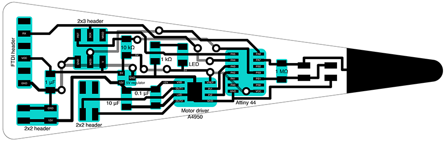
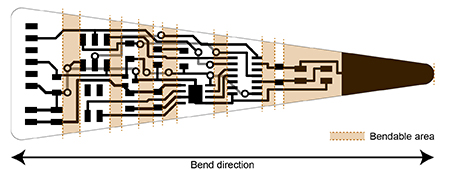
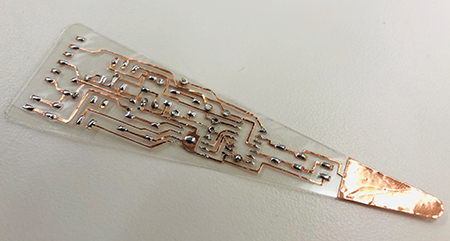
The motion I intended for the soft robot was a simple bending motion into one direction. However, instead of it achieving a single, constant curvature, I opted for more of a spiral shape, as seen in for example shells, ferns, and chameleon tails. To that goal, the soft robot, and thus the also circuitboard, has a tapered shape, with air channels reducing in size towards the tip.
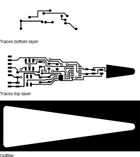
I incorporated all the components required for sensing and acuating onto a two layer circuitboard. The two layer circuitboard was necessary in order to avoid many zero ohm resistors and keep the size to a minimum.
Download
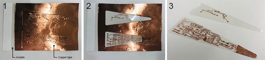
To cut out the traces, stick the copper directly on the acetate and make sure copper is stuck flat on the acetate. Any wrinkles or air bubbles reduce the cutting accuracy, and more importantly, increase the risk of the copper traces detaching from the substrate and curling up while cutting.
Download
Simultaneously, I worked on the soft robot body. 3D printed molds instead of milled molds were the simpler approach to create the fingers. Casting the shape at an angle eliminates the need for two halve molds, as the top surface will be flat. The mold containing the air channels would not be possible to mill, as the air channels will be positioned at an angle.
The molding process of one finger requires 3 molds. The first mold contains the body with the air channels, the second creates a flat piece, and the third mold (the "bath tub" as I like to call it) creates a smooth finish and strenghtens the seams, reducing the risk of the seams splitting and leaking air. It took a couple of trials and different size molds to get the thickness of the thin flat layer and the size of the bath right.
Download
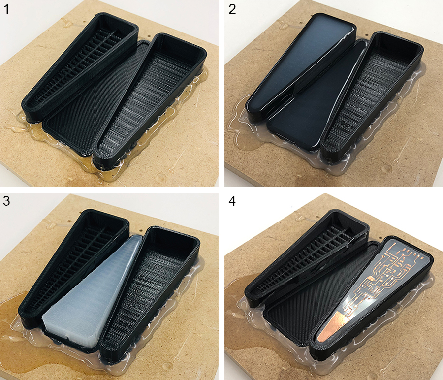
I followed the next steps to cast my parts and glue them together. To cure the Ecoflex I put the cast in a toaster oven at 150 degrees F for 20-30 minutes.
1. I fixed the mold onto a piece of wood with hot glue gun (be generous with the glue). 3D printed molds tend to wharp at higher temperatures, and this fixation will help prevent (at least some of) it. It is important to spray the mold with mold release, as I have experienced.
2. Fill the mold with the channels and the mold for the flat piece with Ecoflex and let it cure.
3. Then join the two pieces by putting a thin layer of Ecoflex (too much will fill the air channels and too little will not bond the layers properly) on the flat piece and put the cast with the channels upside down on that layer. And let the Ecoflex cure.
4. The last step encloses the whole robot in yet another layer of Ecoflex to create a smooth finish. Cut off some of the excess Ecoflex (which poured over the edge in the previous steps) with a scissor or knife. Put it into the bath tub with the thin flat layer facing up. Poke holes with a small needle from bottom to top in the circuitboard (in this image I used a fake circuitboard without components). The more and the more evenly spread the better. Spread a very thin layer of ecoflex on top, place the circuitboard and press it in slightly, to allow for the Ecoflex to flow through the holes. Then cover everything with Ecoflex, making sure that the areas around the finger filled, and let the Ecoflex cure. (The board and components can handle the oven environment at 150 degrees F)
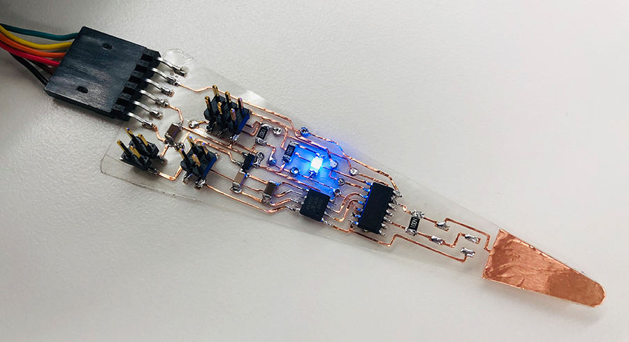
Following the procedures explained above, I molded another finger and incorporated the functioning circuitboard.
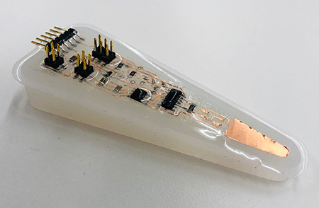
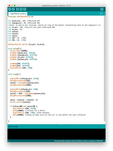
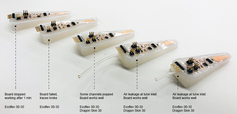
Unfortunately, after molding it into the finger, the board did not seem to work anymore. I later realized I had to change the code as the capacitance sensor values will be different when embedded in the silicone. However, I too hastily removed the board from the finger to test it, breaking circuits in the process.
The next version I made was more succesfull. The board worked before casting. After casting I read the sensor values through the FTDI cable and changed the code to match those values. In my case, I changed the last if-statement to turn the pump on when a value lower than 845 is read. When hooking up the finger to the power supply and the pump (not yet attaching the pump tubing to the finger to avoid inflation), the whole system worked. I touched the capacitance sensor about 4 times, and the pump responded correctly. But then it stopped working. To this day the cause is unknown. The traces and connections all seem intact. The serial monitor cannot read any capacitance values, indicating that something is wrong with the attiny or the trace connecting to the rx pin of the FTDI header.
The following version was even less of a success. After casting, I was already unable to read the sensor values as the rx trace of the FTDI header had broken, and more traces proceeded to break afterwards.
Aside from the traces breaking, I had several theories that could explain the boards to stop working. The board design has a 5V trace next to a 12V trace and I was wondering if that could cause the 5V trace accidently receiving some extra power. I discussed it with Rob and a TA, but that was deemed unlikely.
It was also suggested to me that the platinum in the silicone might, to a minimum, but significant degree, cause the Ecoflex to be conductive. We tested that theory with a volt meter on a very thin piece of cured Ecoflex and it did not prove to be conductive.
I also dicussed with Rob if the components could be overheated due to the fact that they are insulated in the silicone. Rob mentioned that the H-bridge in my circuitboard might become overheated, but that happening within a minute of powering the board would be unlikely.
So, assuming that my board design and the silicone's thermal insulation had nothing to do with the failures, I proceeded to find a new way to protect the traces and soldered connections inside the robot.
As my expectation that the Ecoflex would be sufficient to protect the traces and keep them intact did not pan out, I gathered and tested several solutions.
I received a tip that sandblasting the acetate before sticking on the copper tape could - to some degree - prevent the traces from slipping. A rougher surface provides a better adhesion. The traces, especially at the FTDI header, broke because the Ecoflex was not providing enough strength to keep the component in place. Coating the board with epoxy or a tougher silicone could provide a better protection.
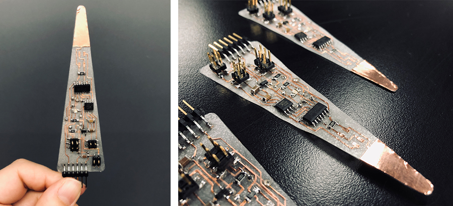
So I sandblasted the acetate before adding the copper tape and creating the circuit. I am not fully sure if it indeed provided a better adhesion. I found that traces seemed to slip less when soldering the board, but that could also be contributed to the fact that I've gotten more experienced soldering these types of boards. But I definitely like the aesthetically pleasing effect the sandblasting has.
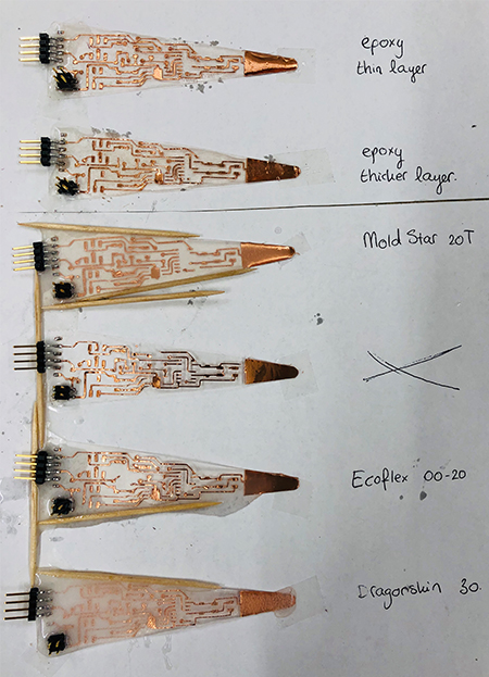
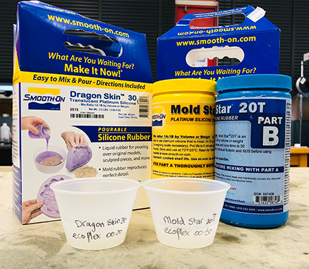
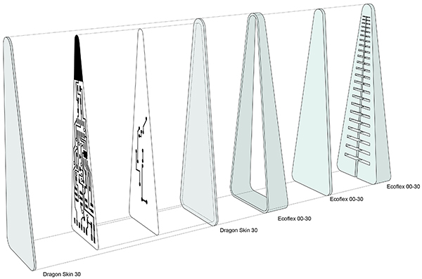
To further protect the traces from sliding or breaking I decided to coat a couple of boards with either epoxy or Smooth-On silicones. I used the Smooth-On website to compare the strength and flexibility of the platinum based silicones that we had available in the lab: Ecoflex 00-30, Ecoflex 00-20, Mold Star 20T, Dragon Skin 30. As I expected, Ecoflex 00-30 is the weaker, more flexible one of the four, so using one of the other three silicones would definitely increase circuitboard protection. My question was, by how much and are they flexible enough for my robot.
I used the actual shape of my circuitboard, because I wanted to get a feel of how the coating would affect the board's bending ability.
A thin layer of epoxy allowed the board to curve in the bending direction, but I felt it was too prone to cracking. Dragon Skin 30 seemed, as the online comparison already reveiled, the toughest of the three silicones and protecting the board the most. And the board still had a nice flexible feel and bending ability. The choice for Dragon Skin 30 was also made because the only Mold Star 20T we had in the lab was already quite old, so using new pack of Dragon Skin was a more reliable way to go.
Before making my final decision I wanted to test the ability of Mold Star 20T and Dragon Skin 30 to bond to the Ecoflex. The answer is problably obvious to those that know the chemical contents of them, but I had to find out for myself. I performed a quick test, curing a layer of Ecoflex and then depositing and curing a layer of either Mold Star 20T or Dragon Skin 30 on top of it. Both bonded well to the Ecoflex.
So, for the last robot I sandblasted the acetate for the circuitboards and used Dragon Skin to cover the traces and components. This required a small change in the molding process. Instead of filling up the "bath tub", I filled it with Ecoflex up to the surface of the cured part from step 3 and let it cure. Then I spread a thin layer of Dragon Skin, pressed in the circuitboard, covered it with yet another thin layer of Dragon Skin, and let it cure.
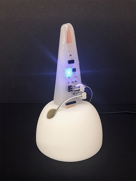
The first trial run went really well. (Even though the video shows some channels popping)
I 3D printed a base for the finger on a PolyJet printer, to hold the finger in a vertical position (when laying flat on a table it has more difficulty sensing a touch) and hide the pump, tubing and electrical wires.
Unfortunately, inflation of the body did not go as well as earlier in this process. In the latest three robots I dealt with leakages at the tube inlet that I tried to fix, but was not able to or the channels popped leaving the robot with a dimishined shape upon inflation (see video above). On a positive note, the Dragon Skin clearly helped protect the traces since the last three circuits that I made and I embedded in it kept on working. Even when I handled the robots a bit roughly when trying to fix the leakages.
I would really like to be able to make one robot with both a properly sealed, reliable body and a working board. I've achieved both during this process, but unfortunately not in the same robot. Now that I'm confident I can make a functioning board and protect it well with Dragon Skin 30, I would like to experiment with new techniques to create a more reliable body, for example by using soft, meltable cores to create the air channels. In addition, I'm not a fan of the aesthetics of the header connections of the pump and power. So I'd like to find a less chunky solution to create the connections.
And... my aim for this final project during this semester was to create a crawling robot. While working on the above, I did this first attempt: