My name is Sinan, and I am a candidate for a Master of Design Studies (MDes) in Technology at the Harvard Graduate School of Design. I research our modern day, brute-force approaches to fabrication in an attempt to propose alternative methods of building that prioritize material complexities over mechanized assemblies.
I currently hold a Bachelor of Architecture from Carnegie Mellon University (PA), where I first began my investigations into making through storytelling and teaching. My undergraduate thesis, entitled “Mycelium as a Remediator of the Anthropocentric Condition,” utilized fictional narratives to probe the ways in which future architects might challenge the brute force implications of progressive manufacturing with mycelial self assembly.
In order to chronicle my work throughout this course, I will continually be updating this website. Join me as I explore, document, and procure throughout the semester!
I'm pursuing this course for two reasons. First and foremost, the apartment that I've just moved into is falling apart in some ways. There's a lot of quirkiness going on, and I want to make it my goal to execute as much DIY home-improvement through digital fabrication tools that I possibly can.
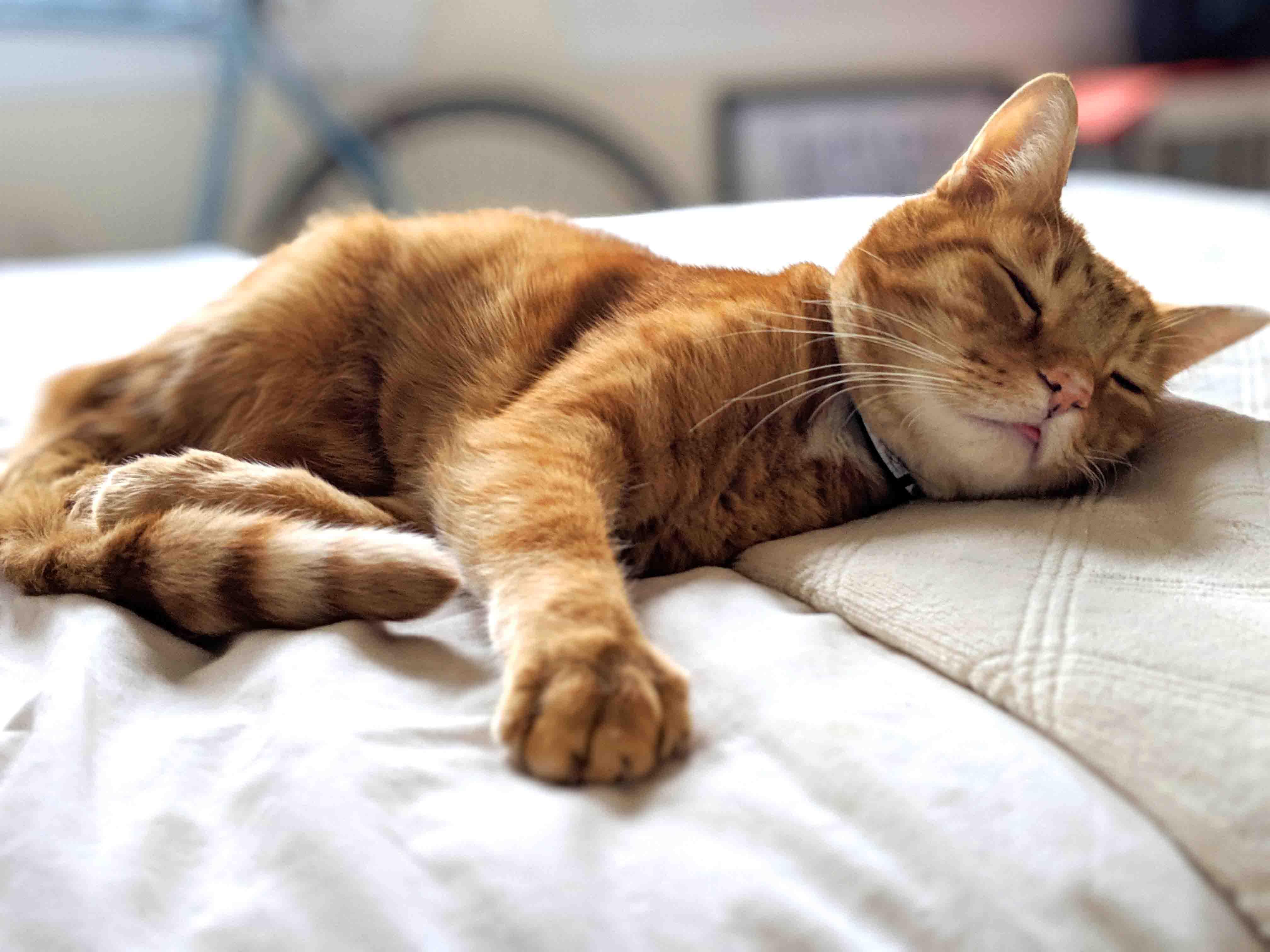
Second, and as far as a global picture and end goal goes, I am part of this class to ultimately build an automated catfood dispenser and feeder. My best friend, Jack, is an orange tabby who eats on extremely sensitive time schedules. It means a lot to me to use a smart feeding system - one that might rely on backup power in cases of electricity outages, or might have the ability to communicate with Jack while I'm afar. Though the market is full of options, they are both expensive and unfulling as far as the strange and niche needs I have. I'm hoping to combine the knowledge we'll gain in electronics, coding, and fabrication to build my own.
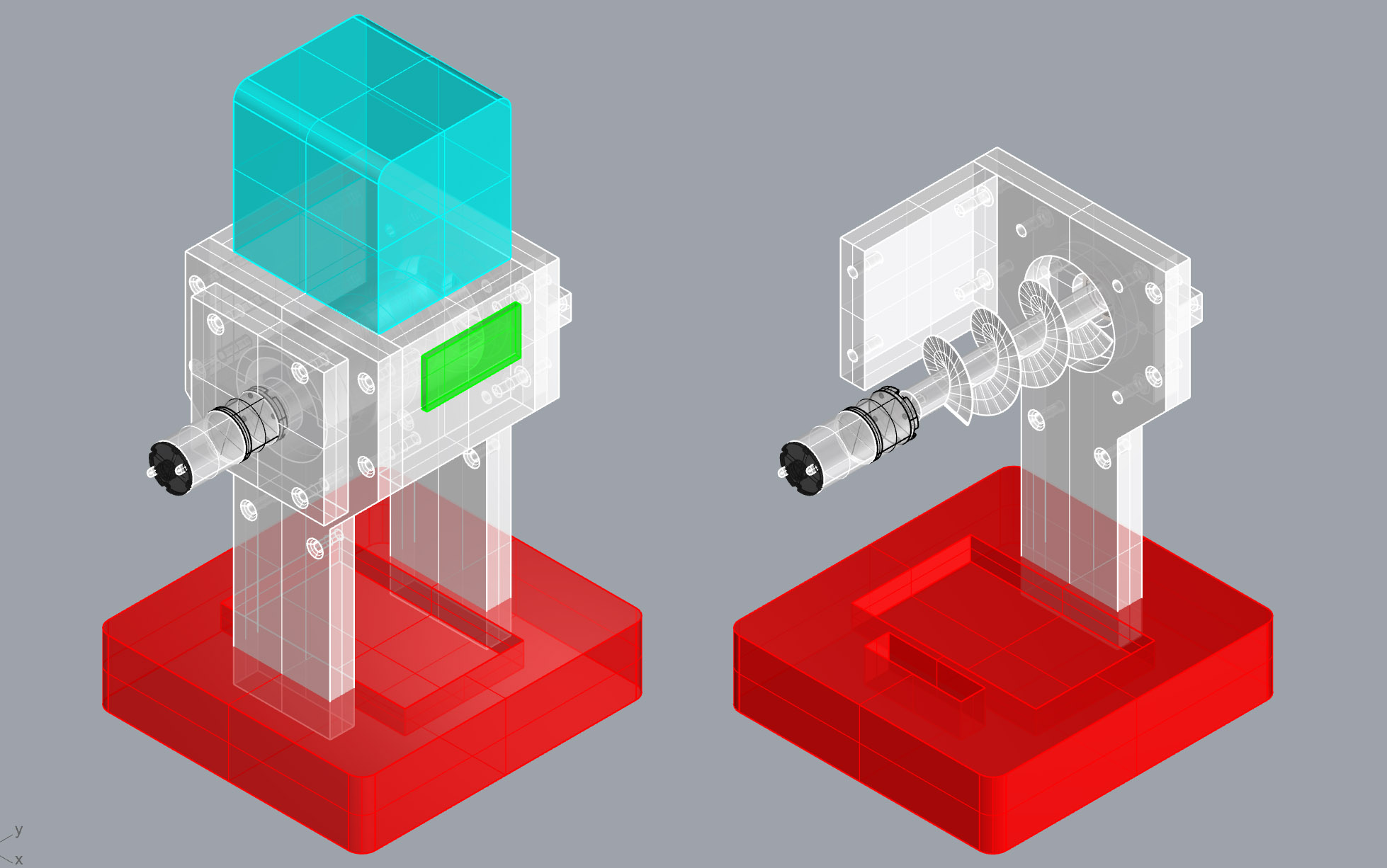
Forgive me for how basal these ghosted models are, but they might give you an idea of what I'm thinking at this point. A simple container containing dry food would be mounted above a structural tower. A rotating auger bit would mediate flow, as food simply falls into the CNC-milled eating tray below. Microcontrollers would control the auger movement on a time-based schedule, but the system would allow for remote overrides in case I want to feed Jack treats.
Weird update: I strangely and recently received the very thing I was hoping to build as a gift. And it works super well. So… I’m resorting to the second thing that I wanted to build for the class: a speaker whose interchangeable sound cavity can cater to specific genres of music.
I'm doing this project in hopes of killing two birds with one stone, as I just entered the Lexus Design Awards competition with it, and have needed to procure a prototype to enter for a video submission. The work builds off of previous work I did during undergrad studies, in which I was studying L-Systems and their representational affordances to look at acoustic design modeling techniques.
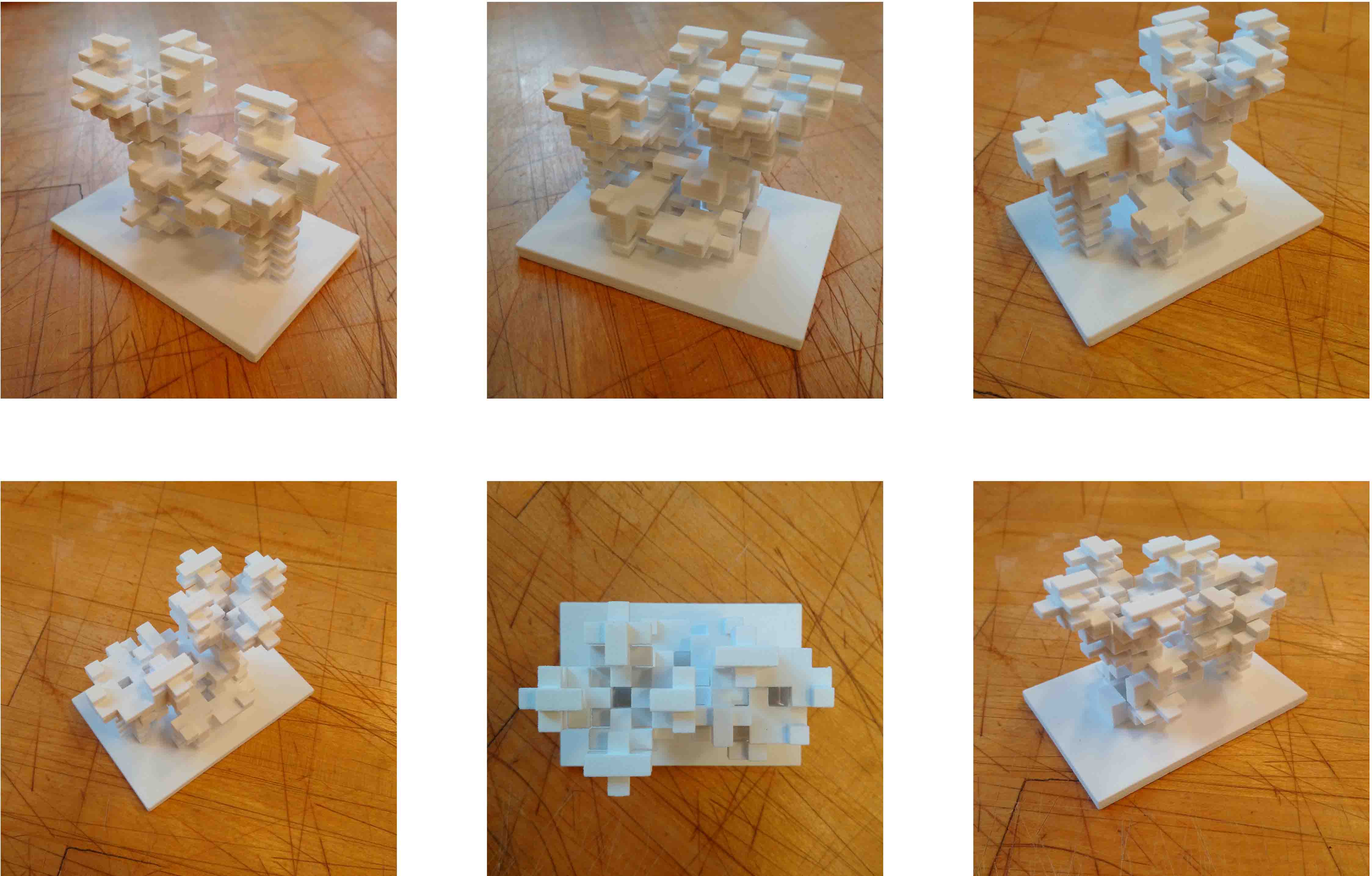
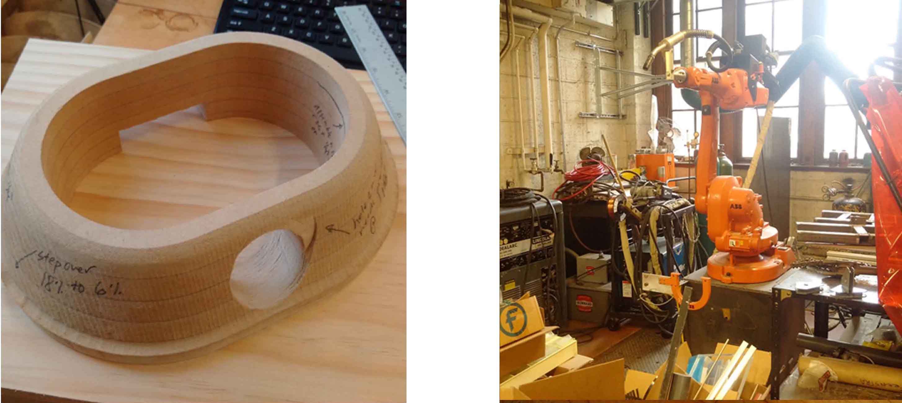
Ultimately, I’m envisioning something which takes advance of 3D printing, robotics, milling, and embedded electronics. At Carnegie Mellon, I already created a prototype out of MDF for the base, which I want to make out of pine or something of the like at the Fab Lab here at the GSD. I also robotically plasma cut the metal brackets, but never assembled them. Below, you can see what I had envisioned about 8 months ago.
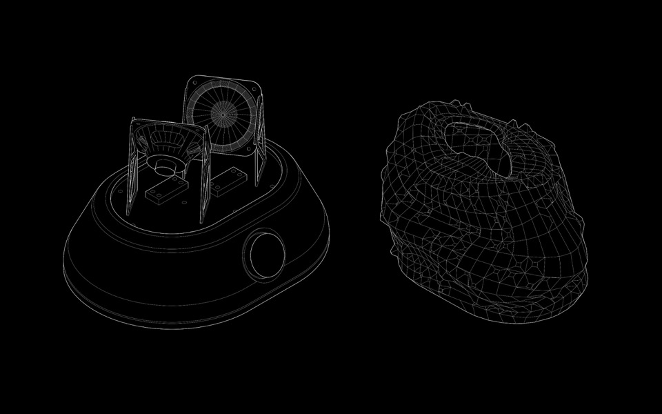
All in all, I'm hoping to work towards something like the following vector drawing - but for this class, I'm hoping to focus on the strobing of the base's light to stay within the scope of what we're trying to accomplish. I'm not too worried about the 3D print for now.
You can see that I have already made an MDF prototype of the housing to test fitment, tolerances, etc. I already had hacked apart a previous speaker board and speaker setup, so I'm simply hoping to hotwire into this for my own needs. I have also already robotically plasma cut the metal brackets needed to uphold my opposing speakers.
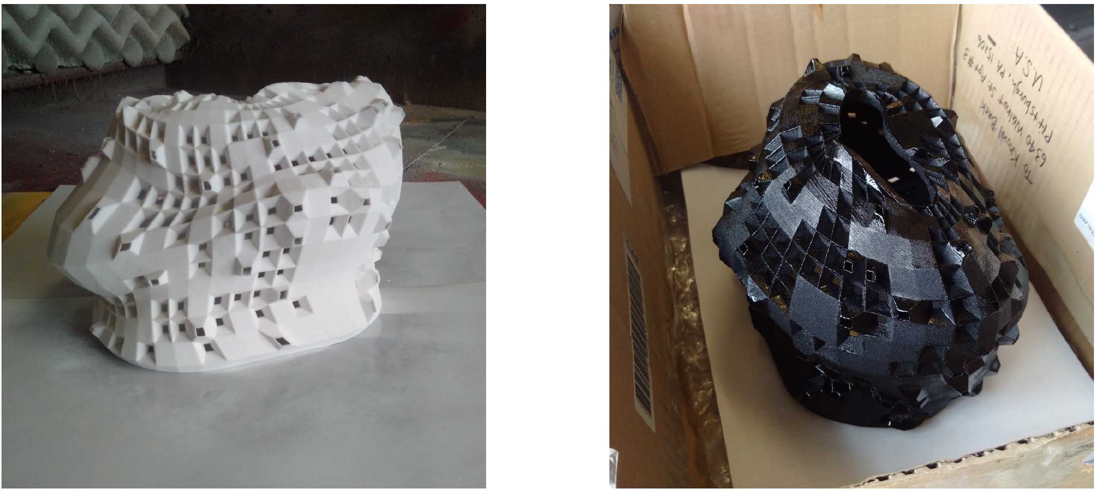
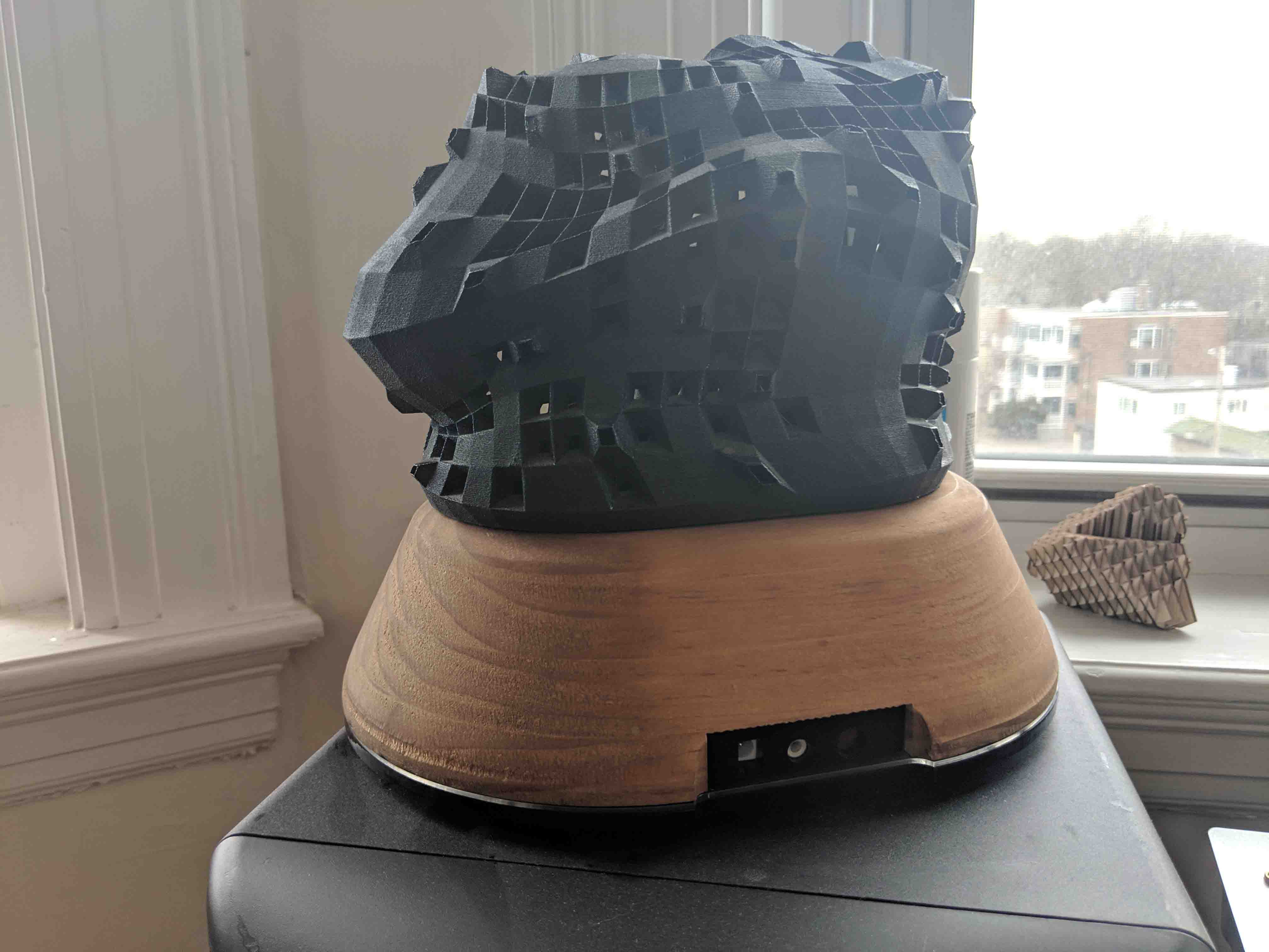
I've already printed the cap out of powder a few months ago, and have been lugging it around with me ever since moving from Pittsburgh. You can see what I have, below.
Stay tuned for more updates - likely regarding milling the real base, soon!
This week, I decided to take the MDF prototype and the tolerance information I learned from it to mill my final form. I laminated several sheets of soft pine together, and after 24 hours of drying, I was ready to mill.
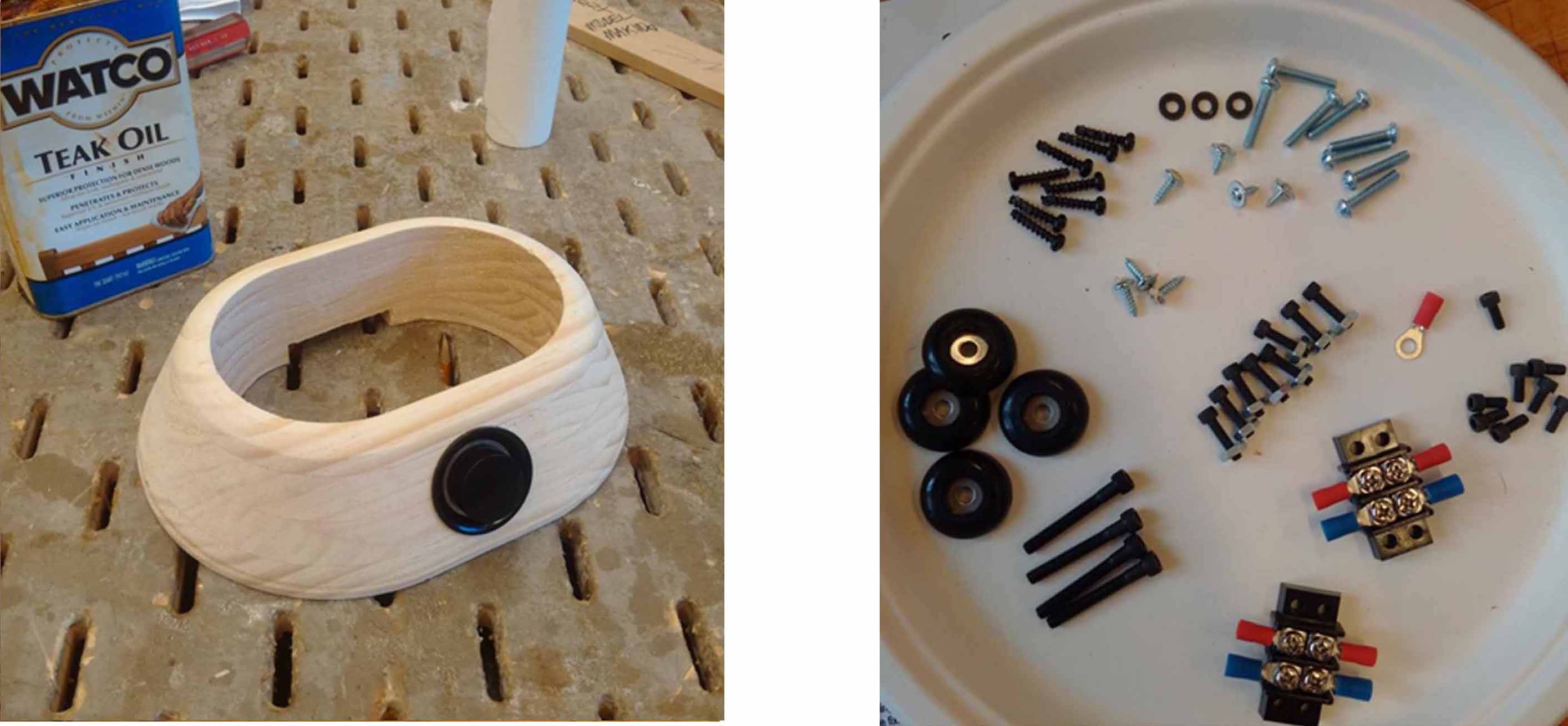
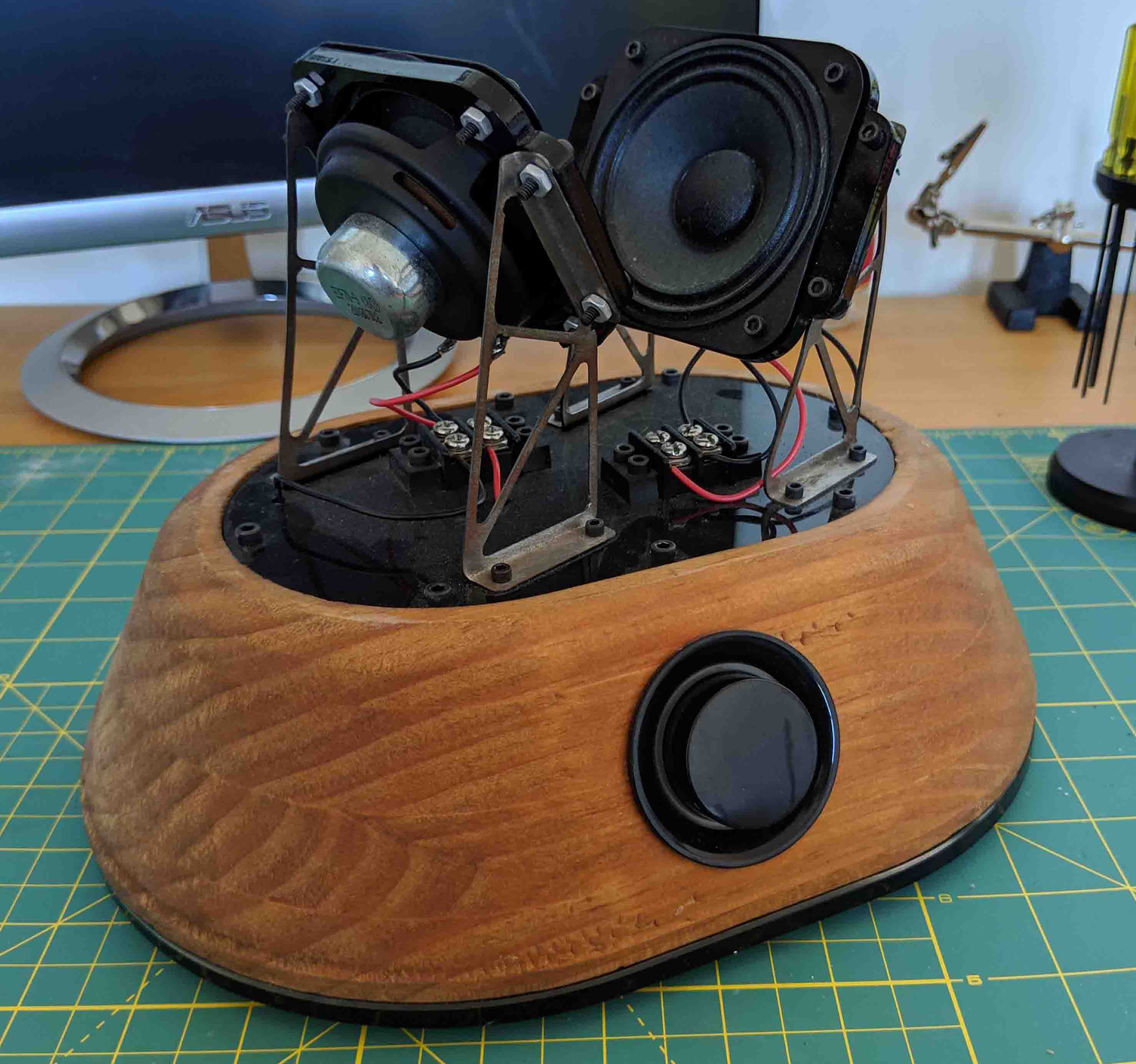
After milling on the Osrund, this is what I resulted with! Some teak oil made the final aesthetic a bit more pleasing. I also was able to start assembling and curating the electronics. The speaker I had hacked apart several months ago had a handy volume knob with an orange LED ring, which I was able to install in front.
I am now planning to take advantage of the LED arrays I've produced and figure out a way to apply them to the speaker. Specifically, I want to create a simple orange led strip for the base of the speaker, to not only match with the orange LEDs of the volume knob, but also somehow throb/pulsate to the beat of whatever music is playing. I'm not too worried about pulling this off, but still need to scratch my head over it for a few days.
I don't think I'll need to create a knew board for processing per se, but definitely will need to mill one for the LED strip. We shall see. I have a feeling I can just tap into the power unit of the preexisting board and the speaker output to get a pulsating signal.
The last thing I did this week was to lasercut an acrylic top plate and test the electronics' fitment. Everything seems to be coming together nicely. Would be nice to 3D print a housing inside to mount the boards to, though. Right now they're all jiggling around.
Some considerable development this week, and I’m excited to share with you!
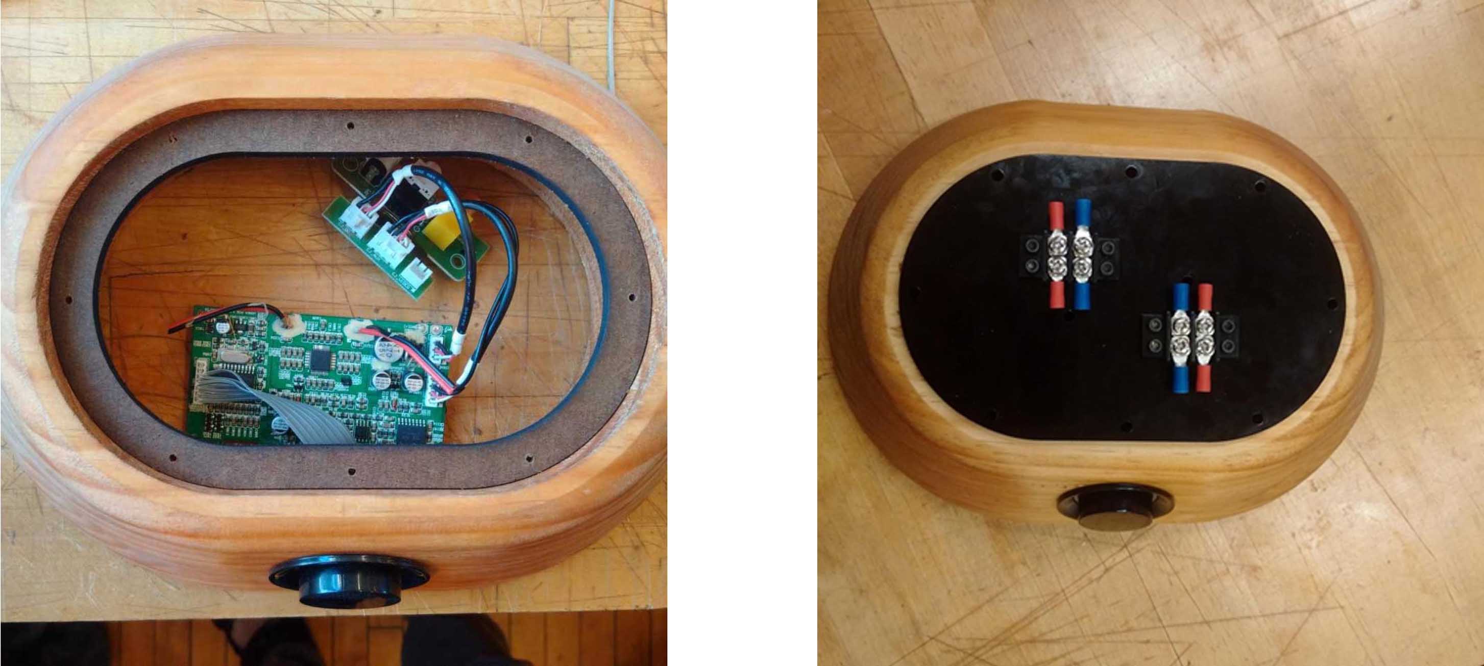
I started by assembling the plasma cut brackets and speakers atop my acrylic plate, and laser cutting the bottom plate for the actual speaker base. I also laser cut a clear acrylic plate that will be sandwiched between the wood and bottom plate, through which my LEDs will hopefully strobe. But more on that next time…
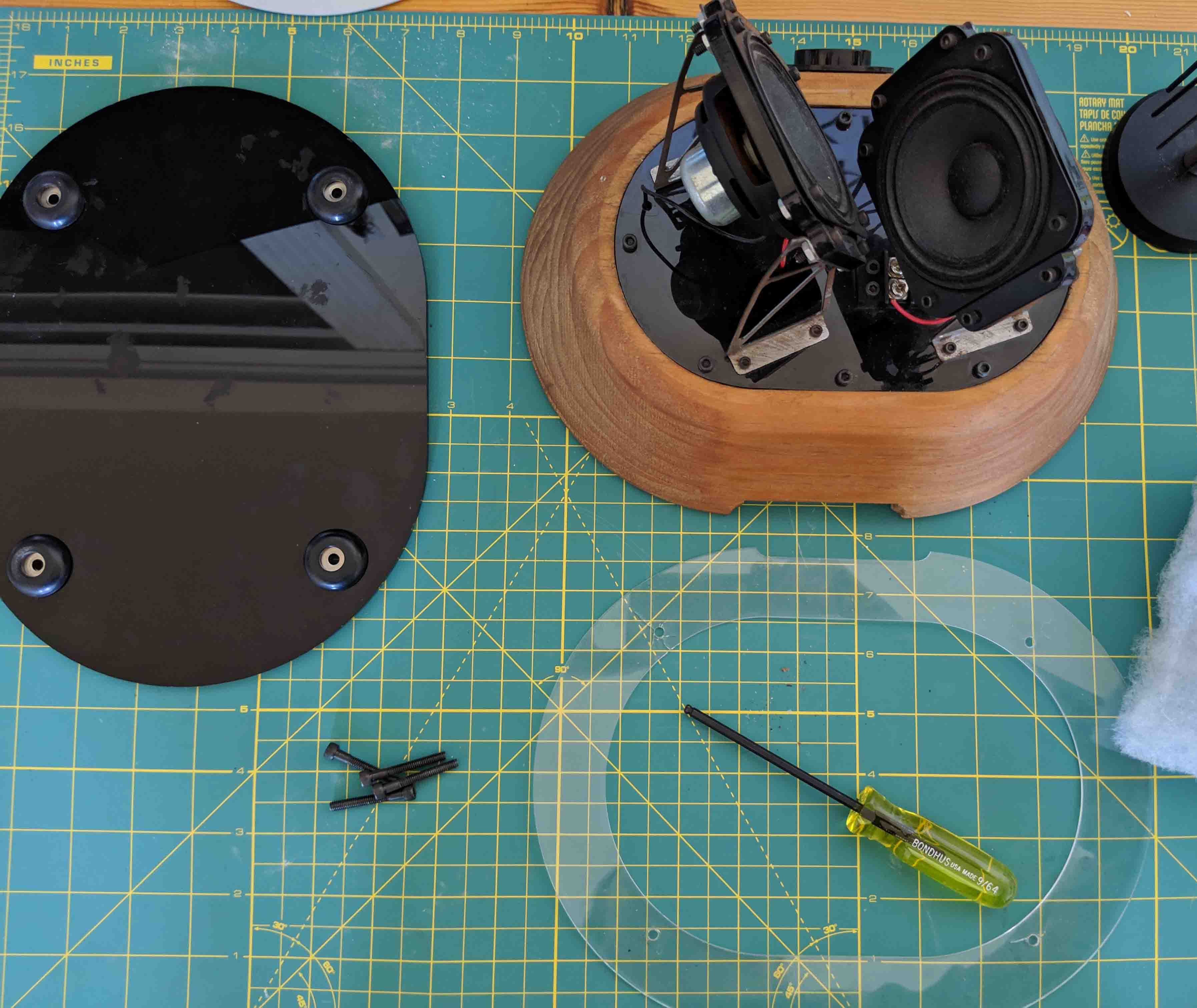
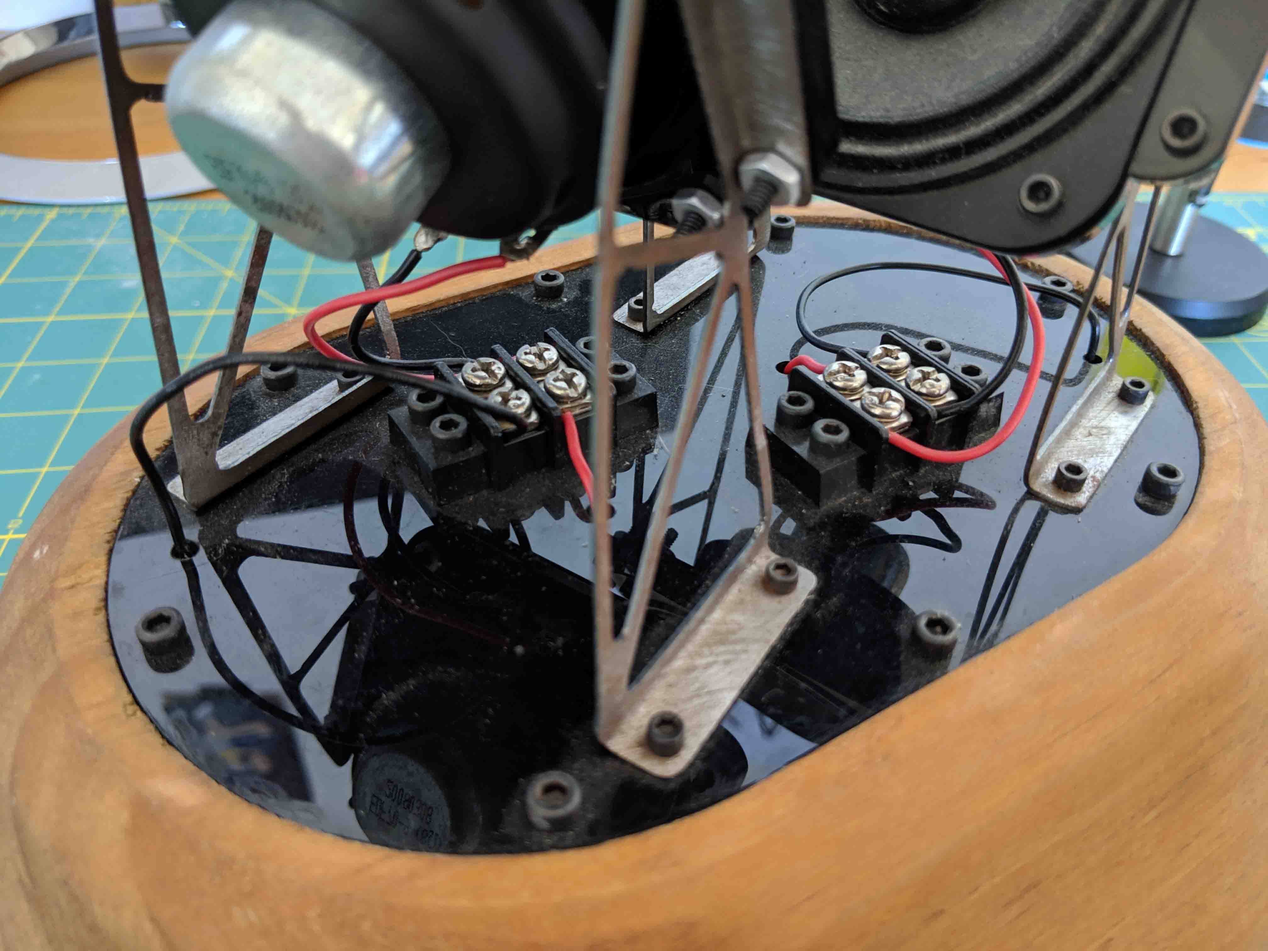
Below, you can see a detail of the hardware which I used for the top plate. I decided on all-black hex screws with matching black hardware. I wanted to expose the wiring and connections for no other sophisticated reason but that it looks cool. I wish the metal brackets were also black, but I’m so happy with their finish that I just don’t think it’s worth possibly screwing up.
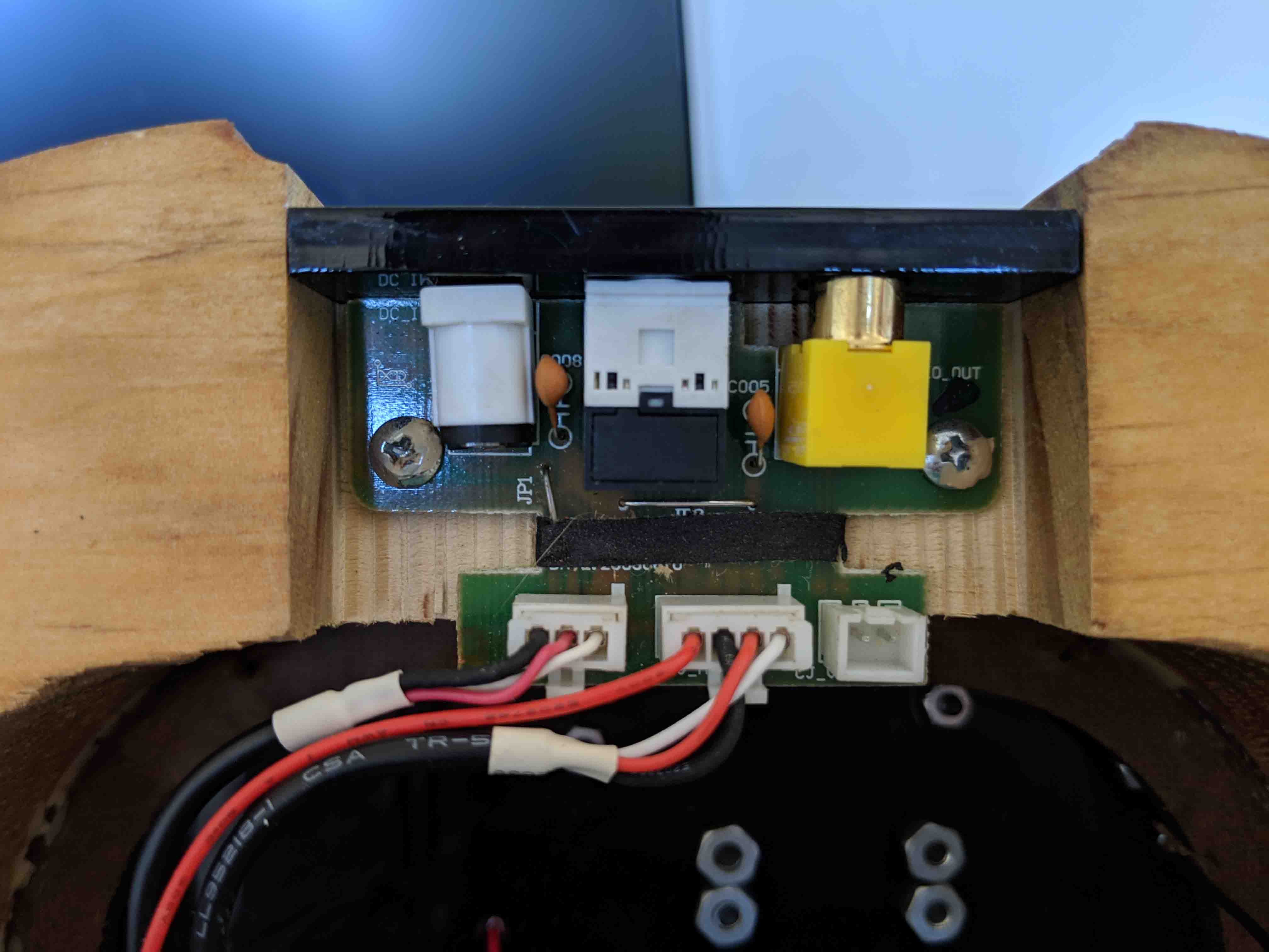
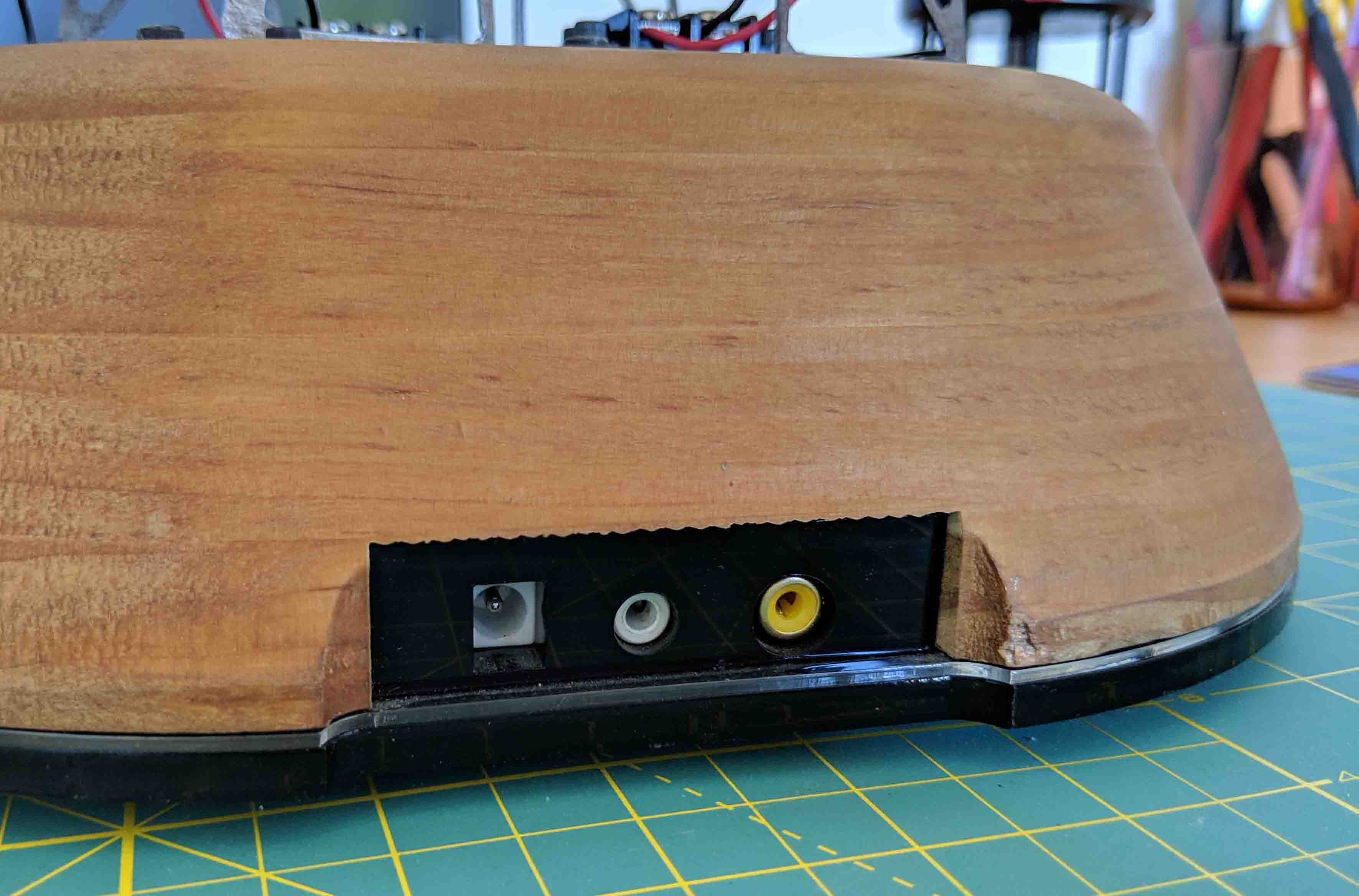
I also laser cut a little rectangular strip with cutouts for the preexisting power and audio board that came with my salvaged set of speakers. This slots into the wood base, as pictured. I relied on friction fitment and my best friend, ZapAGap, to get that sucker in there nice and snugly.
Here’s a better idea of what that clear acrylic is for. I eventually want the strobe to be orange to match the orange of the power/volume knob, so I decided to go with orange LEDs through a clear acrylic layer at 1/16” thickness. I also have the option of using clear LEDs with fluorescent orange acrylic, but Neil advised that this might not be the best route. I also don’t want the sliver of acrylic to look orange from the exterior - it’s all about the element of surprise.
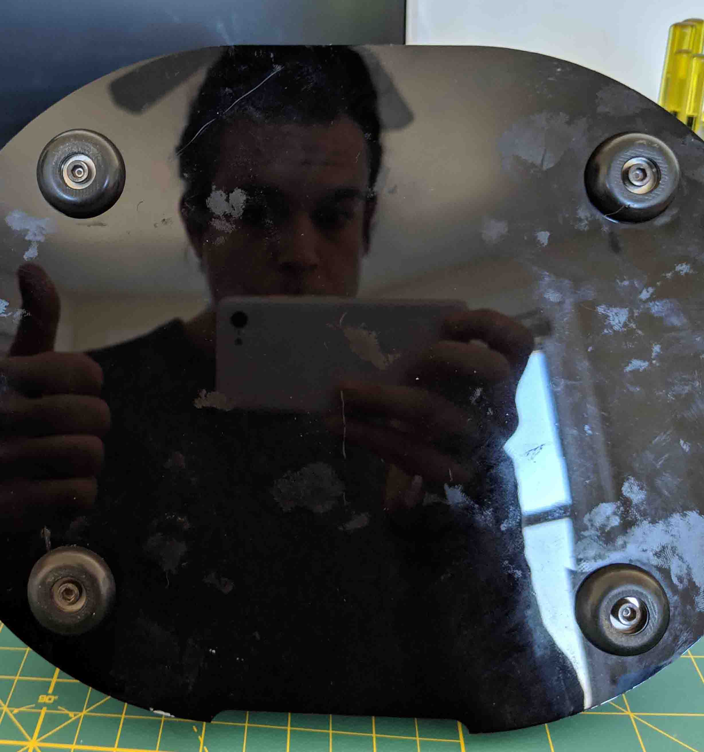
I also sourced these cute rubber feet. Rather, I stole them from a Fender bass amp that I haven’t been using. Kind of pleased with how they look. The screws here are through to the base, so those four screws keep everything together and are the only things needed to knit it all together.
Although I’ll be disassembling this again soon to get the strobing going, I wanted to assemble this thing to check for fitment and see how the clear-on-black acrylic looks. I’m pretty happy with it!
And to continue with the theme of assembly, here’s an image of everything so far!
Next up will be the actual strobing of the LEDs at the base. I think I’ll rely on a 3D-printed housing to hold some strip LEDs, and a simple transistor to mediate audio-in. I think I’ll have to slice into the 12V in on the actual board, and I definitely don’t want to rely on a 9V battery. Stay tuned!
Today I decided to tackle the LED orange strobing effect that I so desperately want for my speaker. Spoiler alert - I got it working, and decided to apply it to the volume/power knob instead of the base because I really liked the visual effect!
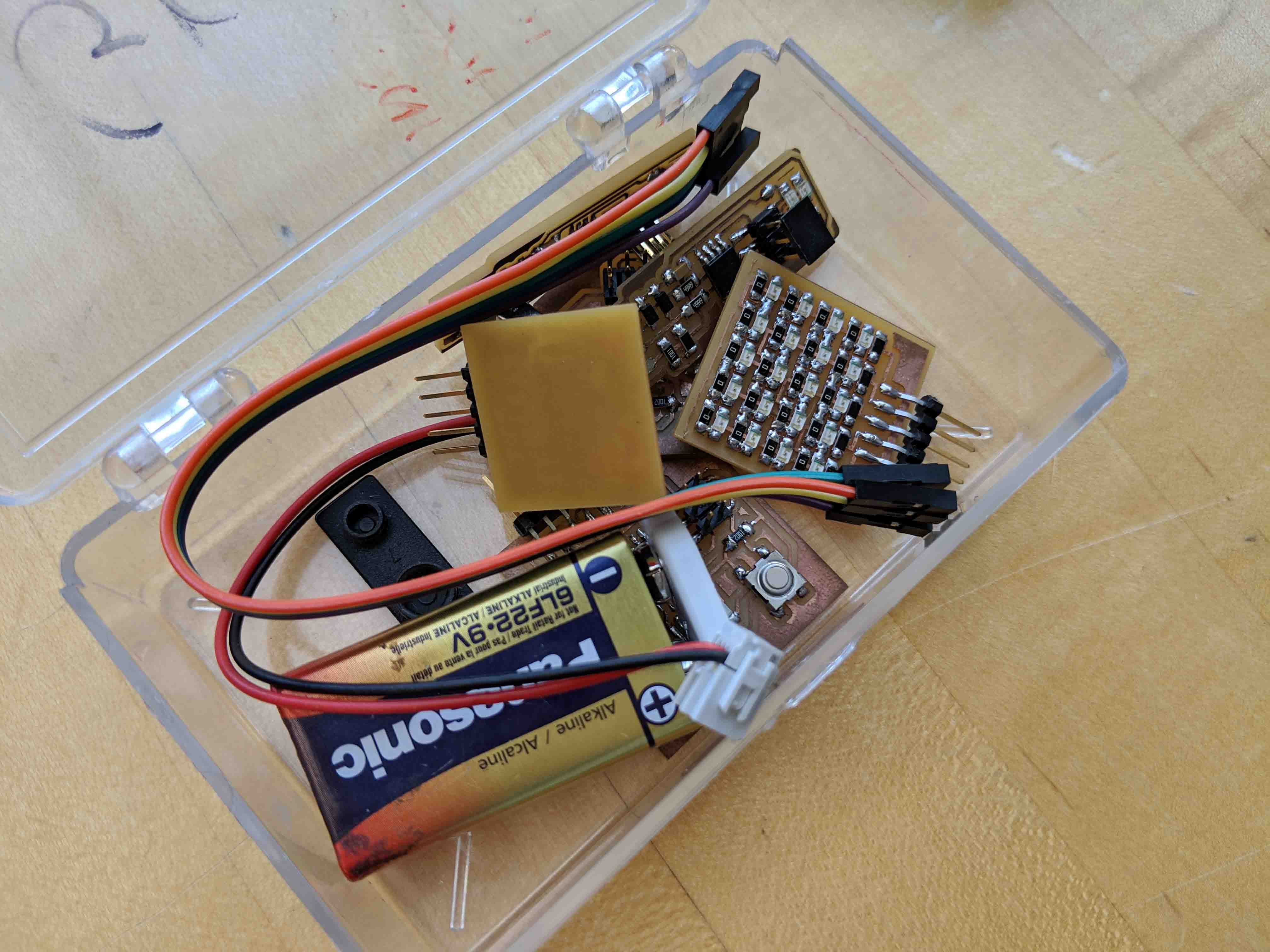
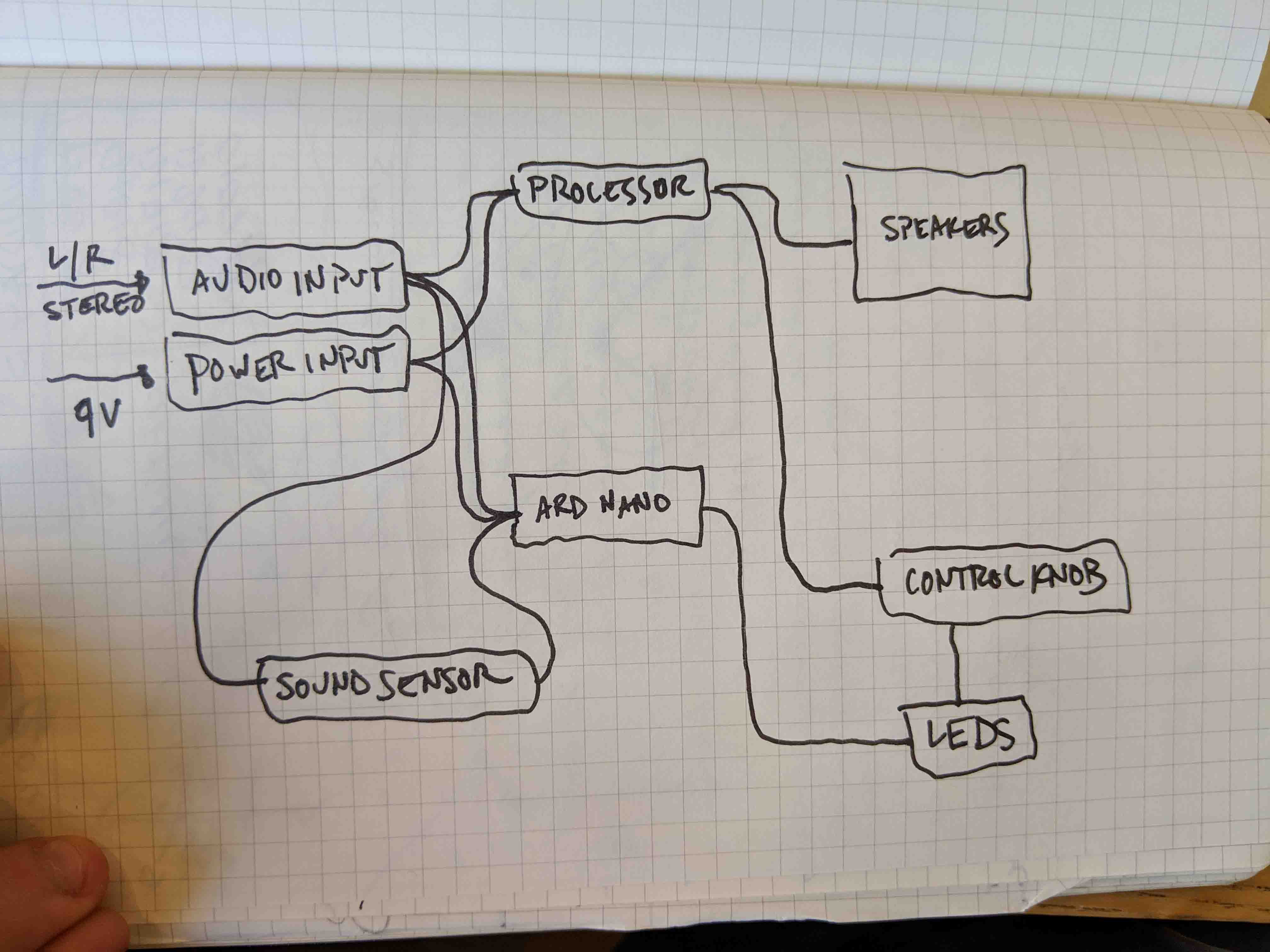
Before starting, I had to plan how the logistics of the circuitry would play out. Below, you can get an idea of what I accomplished. I had to splice into the audio input jack to Y-feed it towards a sound sensor, whose signal would be interpreted with an Arduino NANO. This NANO then communicates signals with a very simple for loop and sends them to the LEDs on the power knob!
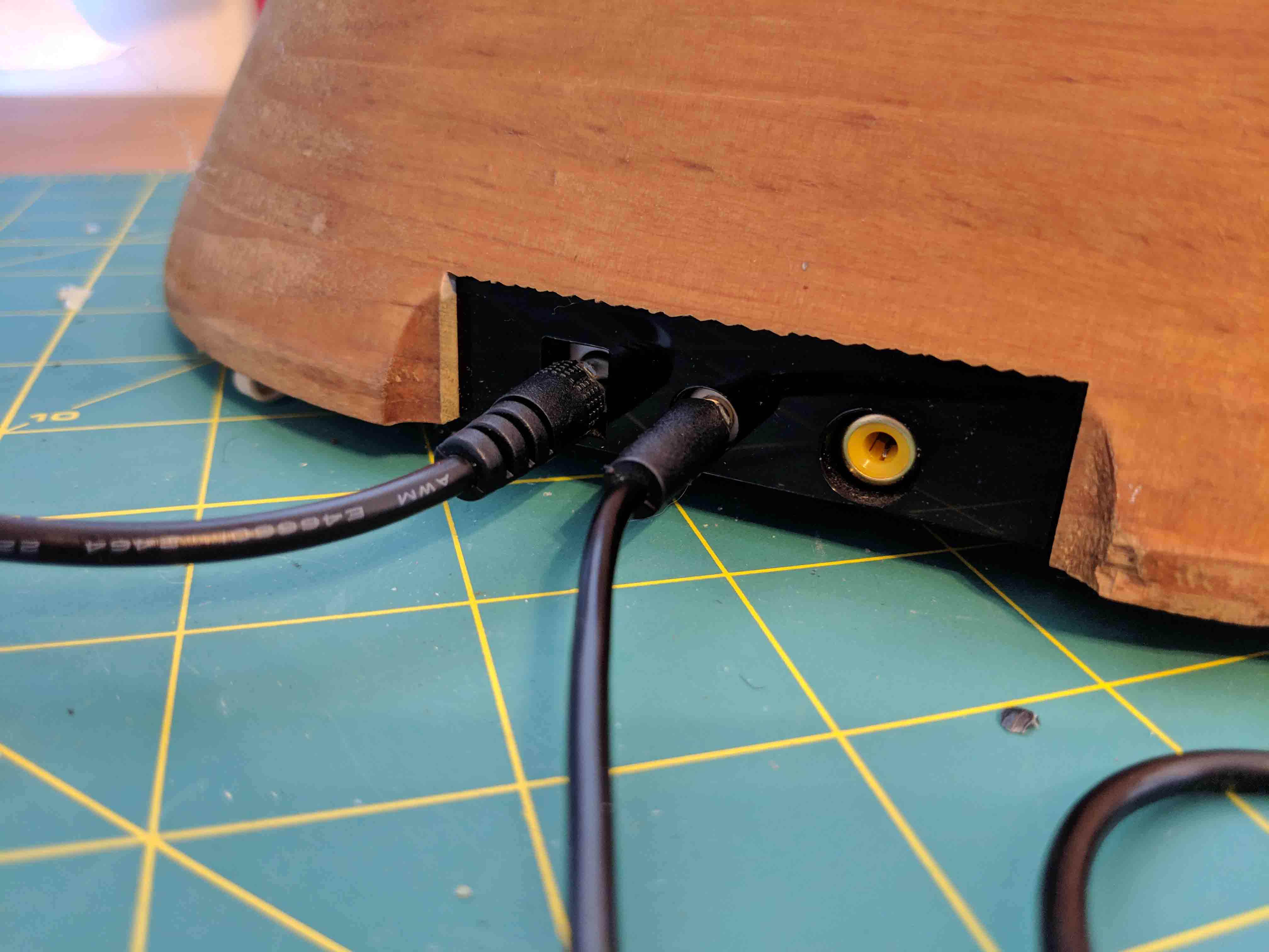
First, I had to change the input cables to make sure I found ones that weren’t too snug and that fit in the jacks nicely. This only required some rummaging in shop.
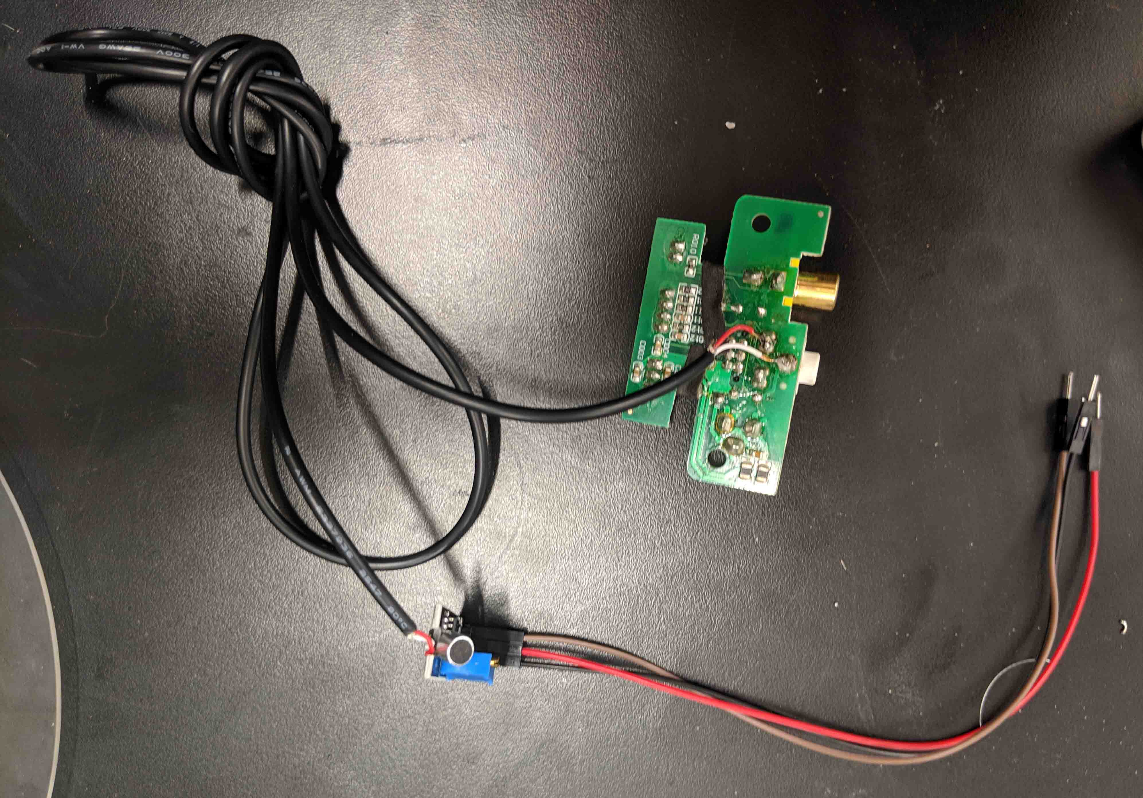
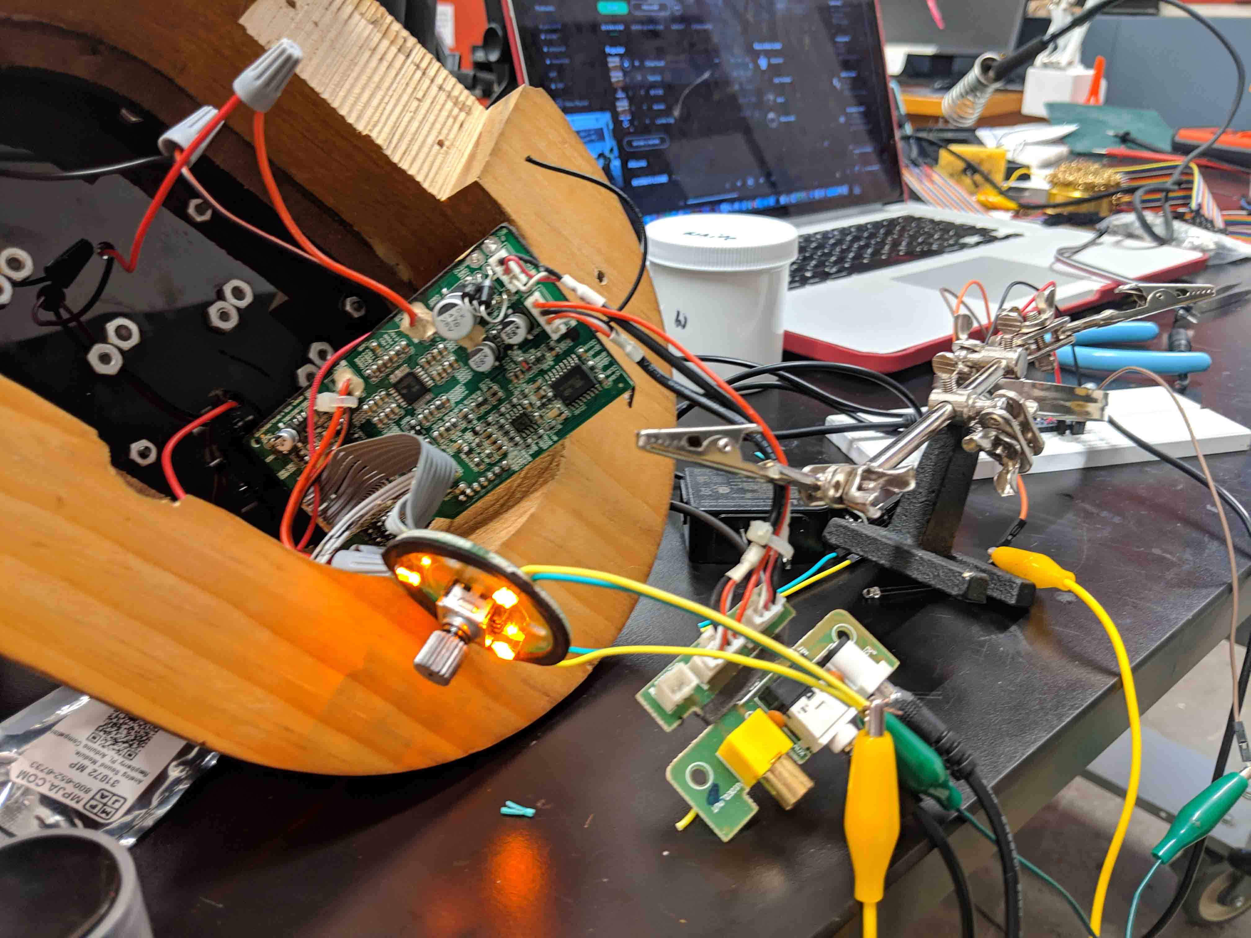
I admittedly had to scratch my head for a while on this one, but I realized that I could bypass the microphone input on the sound sensor with just a simple audio feed that spliced from my audio input! So, I took the power/audio board that I already had, soldered on some extra leads, and used a spare audio cable I had lying around. The other end of this cable fed into the microphone input, one L and one R. I permanently soldered these on, as well as some jumper cables for ground, VCC, and digital out.
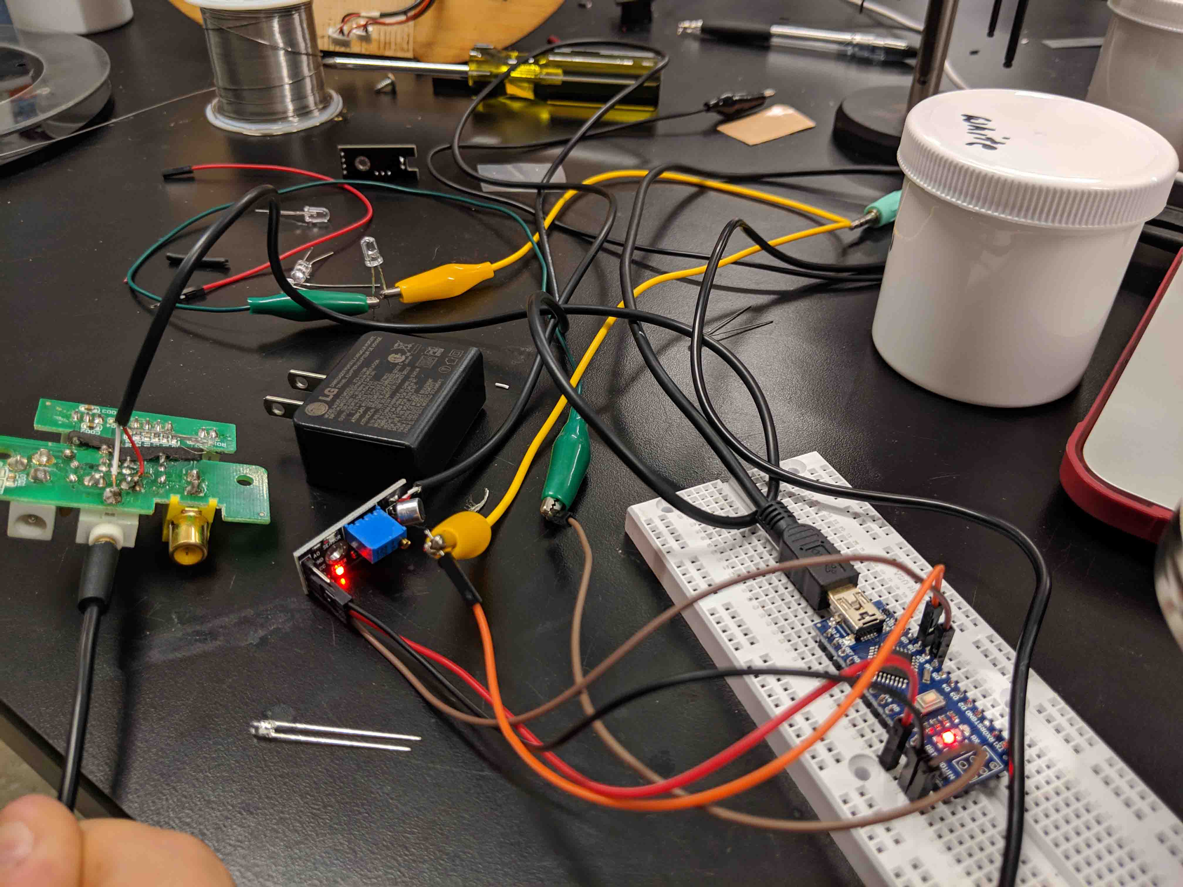
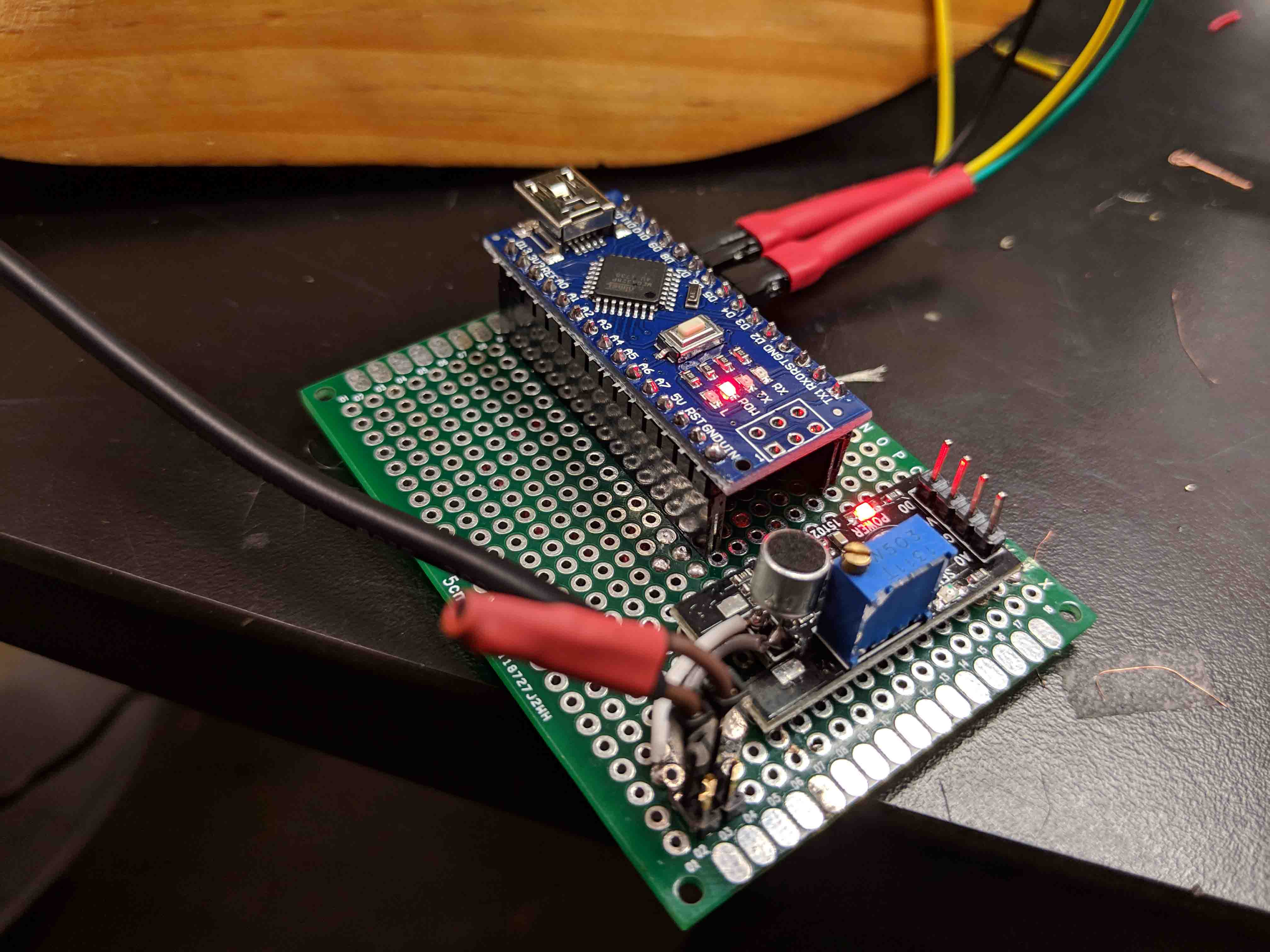
From there, all I had to do was attach ground to ground, VCC to 5V, and digital out to pin 7 on the Arduino UNO. I used some jumper cables for quick problem solving, so forgive this mess. It’s actually a lot more simple than it looks. I also attached everything to a mock-LED to make sure that any traveling signal would be processed by the Arduino UNO and resent back to the LED after I set up the code.
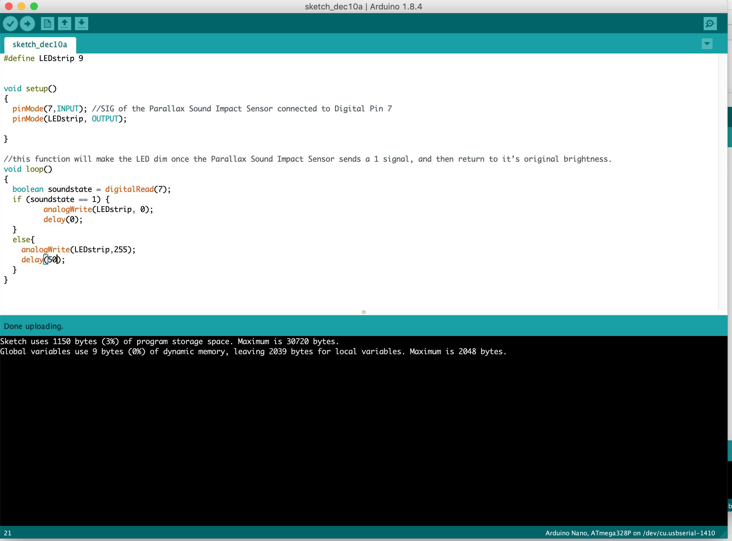
Then, all I had to do was write a simple sketch that incorporated an if/then statement. You can see that I set it up such that when the sound sensor doesn’t sense anything, the LEDs are on instead of being off. Though this is a bit counterintuitive, I wanted the LEDs to always be on if no sound is being sent through, to let the user know that the speaker is actually on. So, any sound signals are processed by flickering, or rather, the lack of light. This happens so quickly that one can’t really tell, but it’s a point I should mention nonetheless.
I hooked everything up, sent the program to the NANO, and voila! The LEDS turn on, and flicker to music!
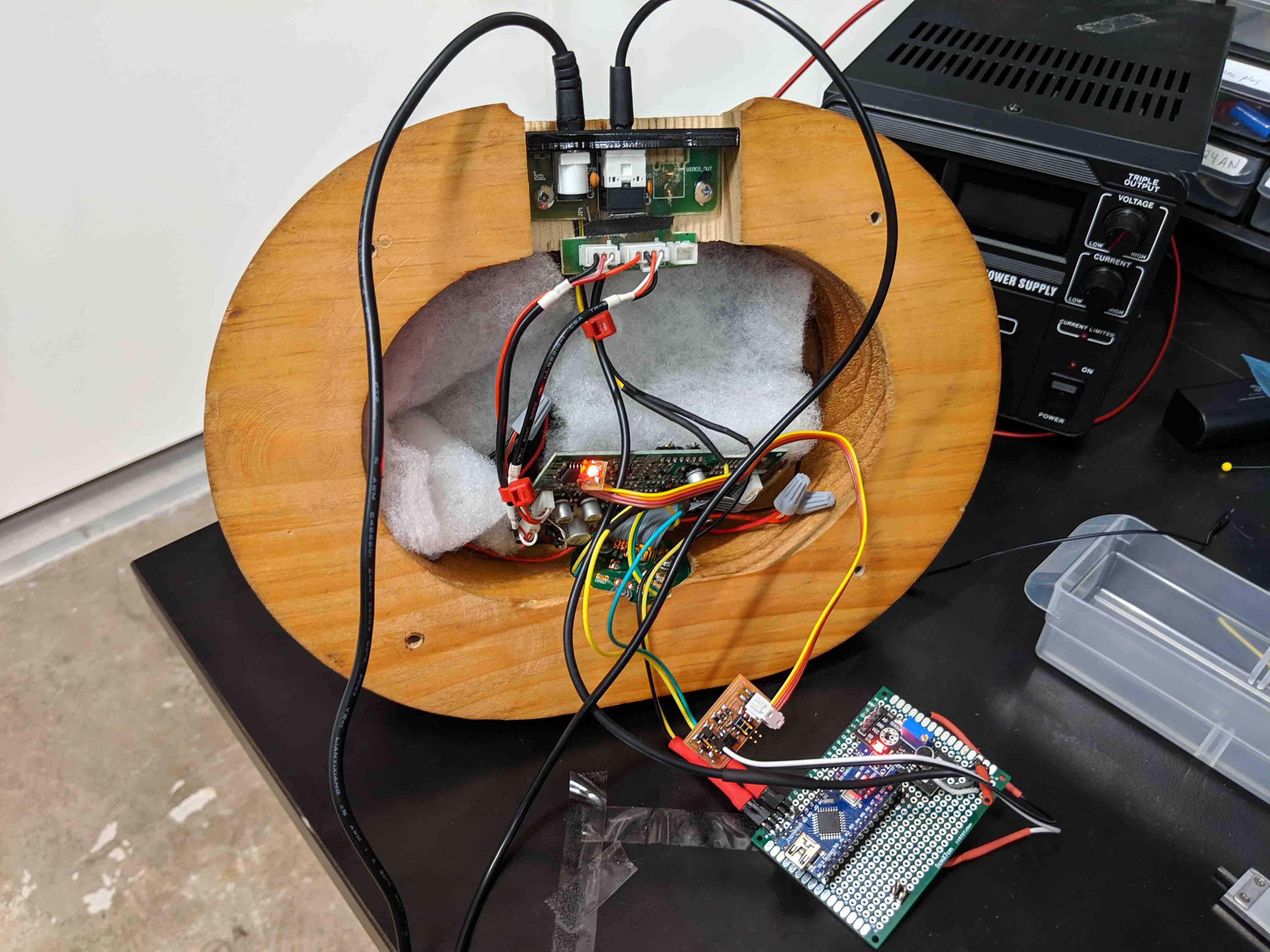
At this point, I have to splice into the power supply on the green board to figure out a way to give power to the Arduino NANO. I might 3D print a housing for the inside of the speaker to mount all these boards and processors to, but I also think I can just cram the boards inside the housing with some soft padding material. In a few days, I'm going to be designing and milling a board that turns on a RED led when power runs to the speaker. But other than that, things are looking good at the moment… stay tuned for final updates!
Before designing and milling the new board, I figured I’d take all the Arduino stuff I worked on last time and solder them onto a clean breadboard.
And after some shrink-wrap and a lot of hidden wires underneath…
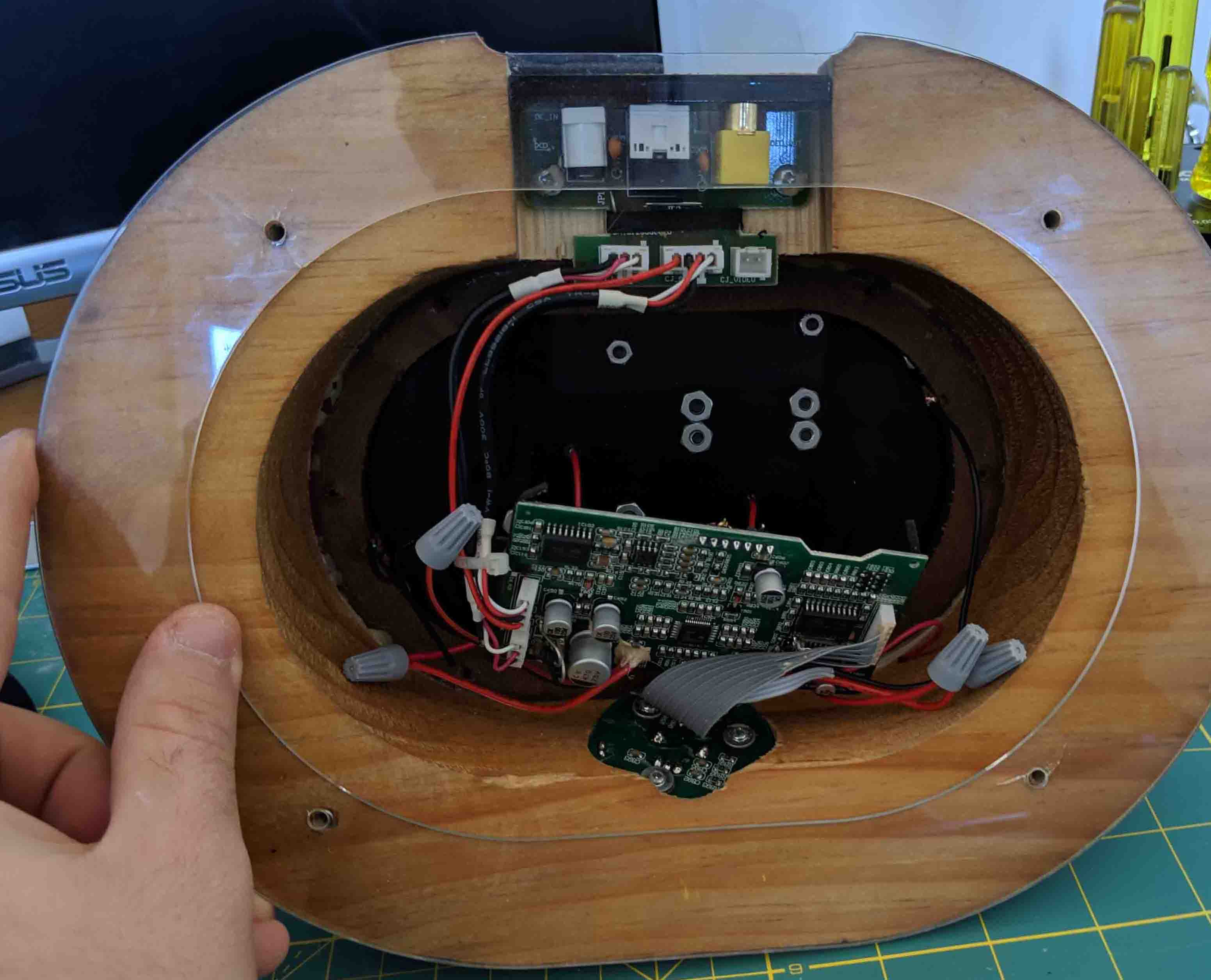
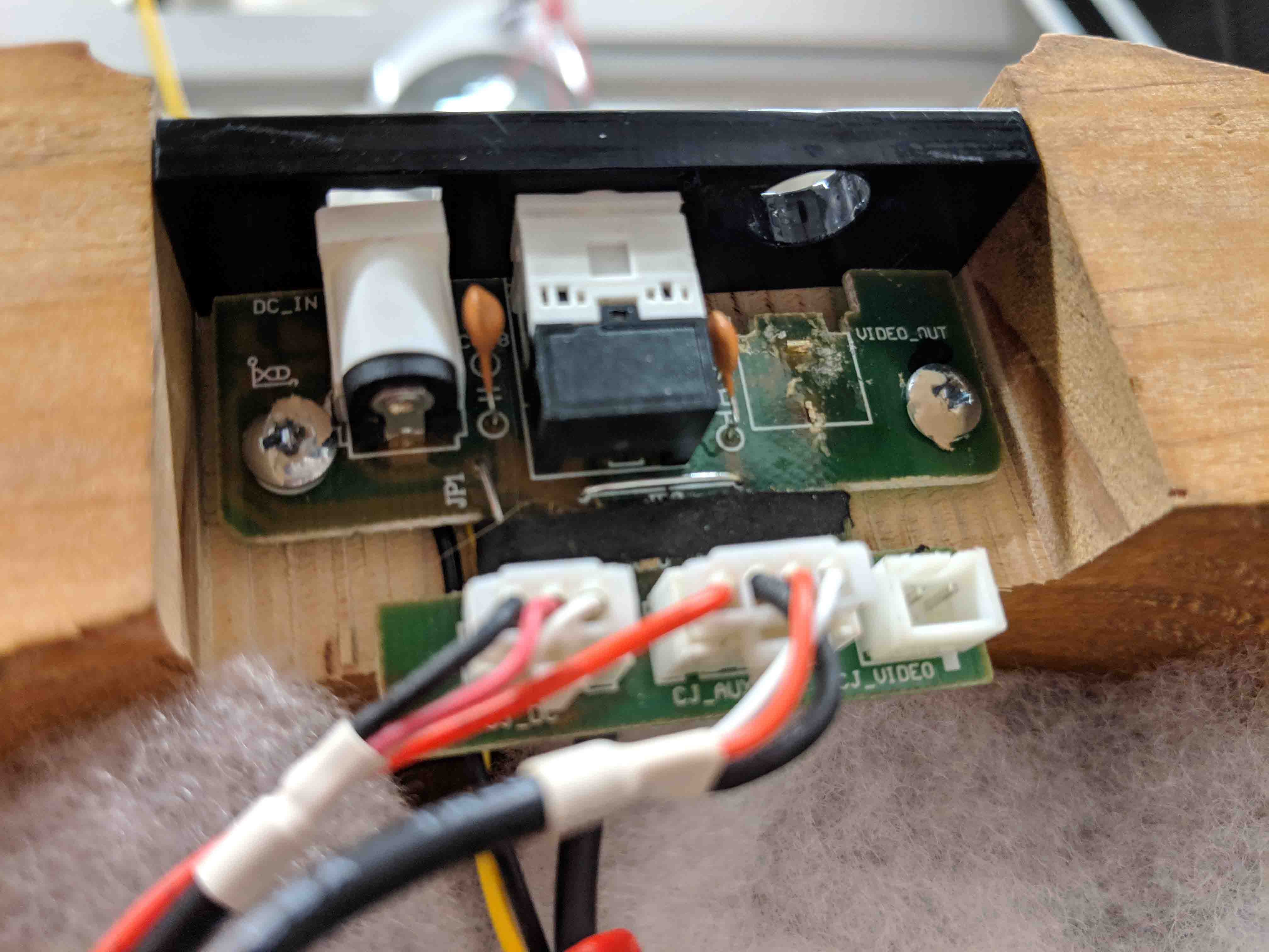
Next, it was time to desolder the video-out unit from the board, as my LED would later get installed there. Also, I didn’t need a video-out for my speakers, obviously. Conveniently, the hole would help me out, later!
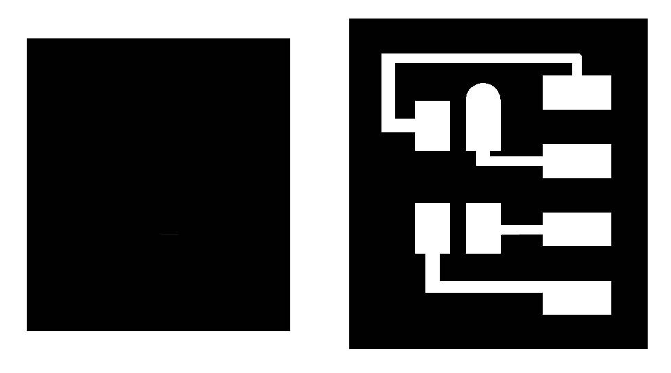
Then it was time to design the board. I worked off of Neil’s PWM LED board, but stretched it out a bit, and added leads to allow for a 2x2 header. I wanted my LED to reside on a separate board, which would be connected with a ribbon cable to the processing board.
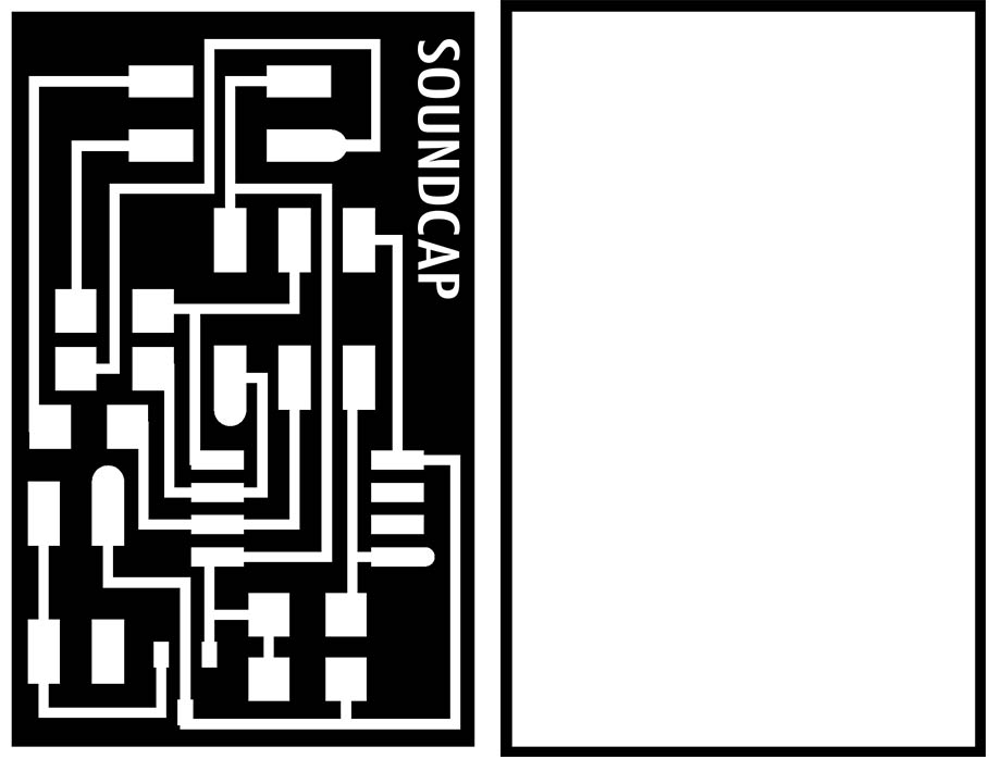
As such, I had to quickly mock up the LED board. This allowed for four leads to be literally soldered on. No fancy cables and headers, here.
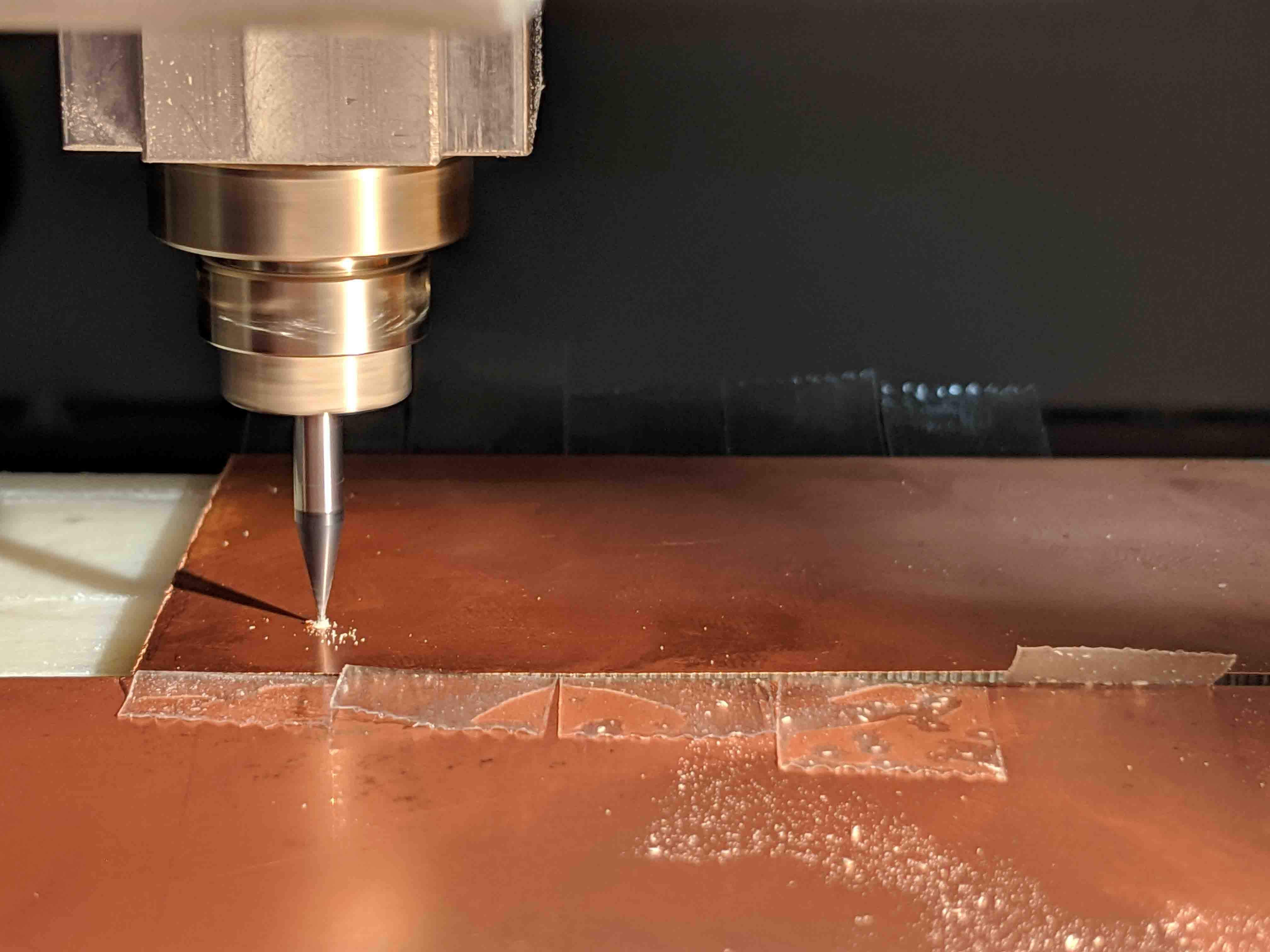
Then, off to the mill. Surprisingly, this was super hard for me, and I had to mill either 4 or 5 times (I don’t remember). Every time, the processing board would mill fine, but the LED board would get destroyed. This was likely due to its super small size. I eventually had to double sided tape the HELL out of the blank in order to get it to work.
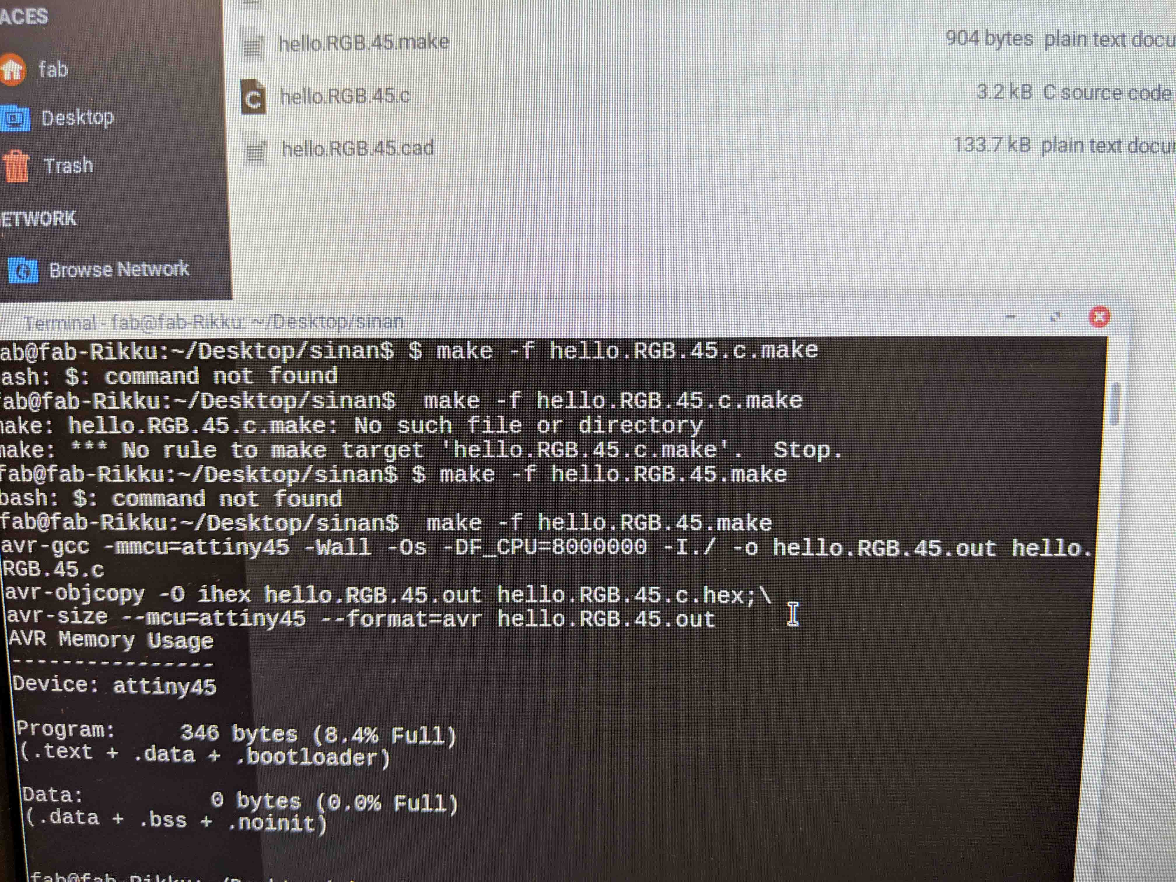
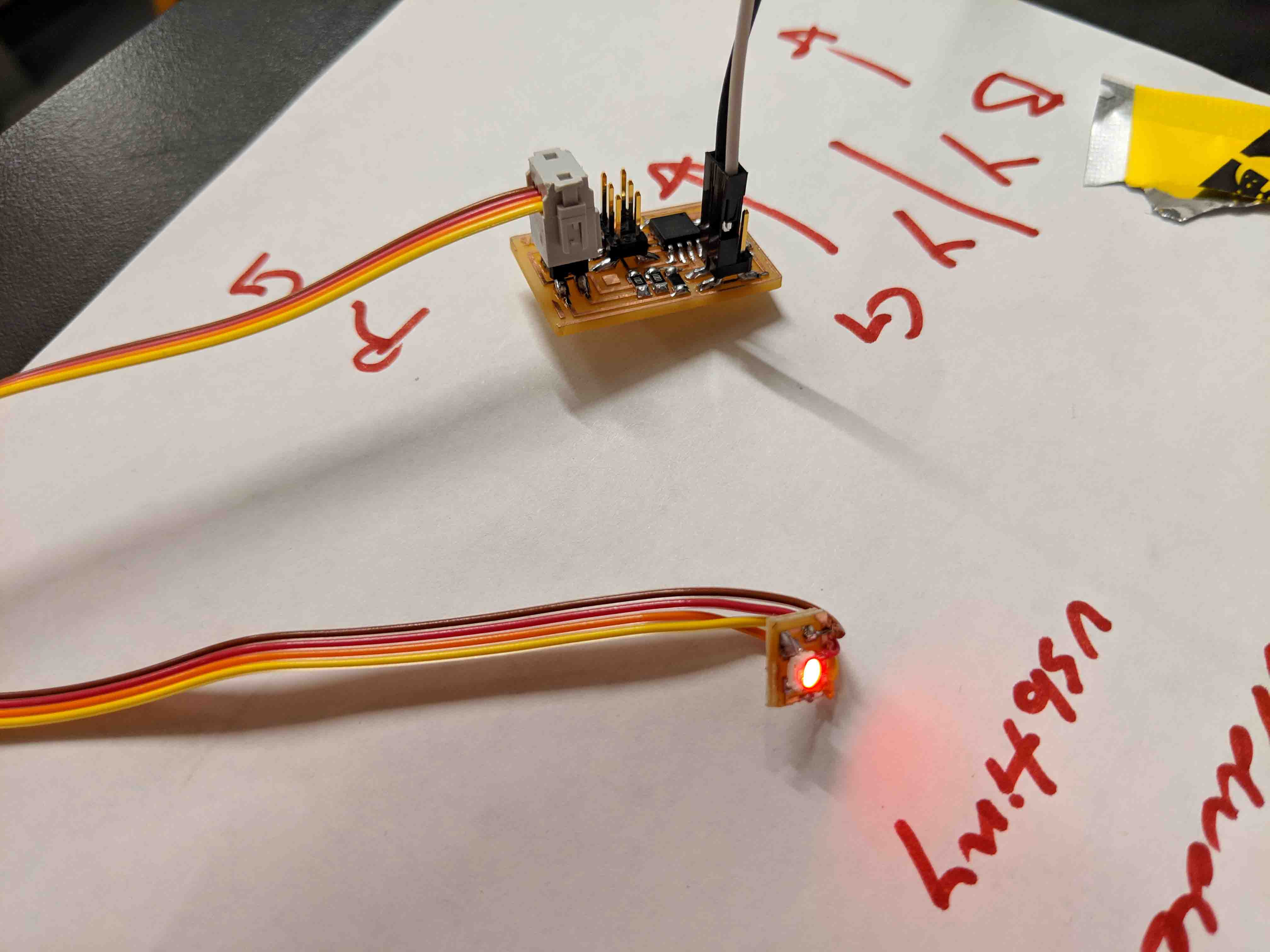
Stuffing was pretty self-explanatory. At this point, this is all second nature to me. As far as coding goes, I didn’t get any dreaded “rc=-1” errors, and was able to make my .hex file just fine. I altered Neil’s code so that the LED only showed red, since I had some orange acrylic and thought that the red would most accurately relate to the orange LEDs already on the speaker.
And finally, the board(s) after coding! Whenever the board receives a power signal, the LED turns on. Simple, but all I needed the board to do (to show power to the speaker unit), so I’m happy with this.
At this point, I started packing everything up, and used some hot glue to sketchily adhere the second LED board to the backing of the black acrylic.
After packing everything back up and carefully screwing everything together, I tested the light - and it works!
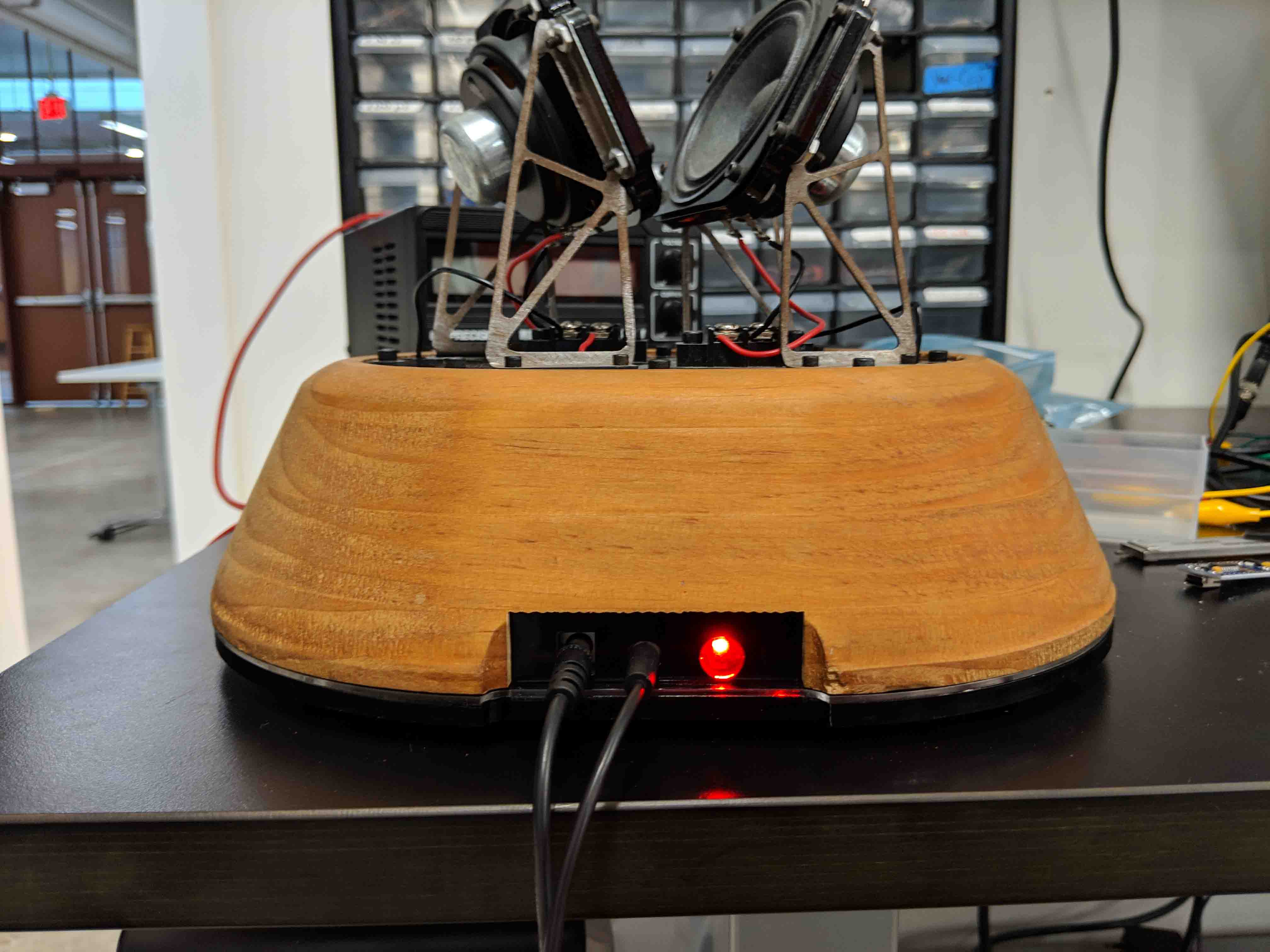
Just have to clean everything up and photo document, but for the most part, everything is done!
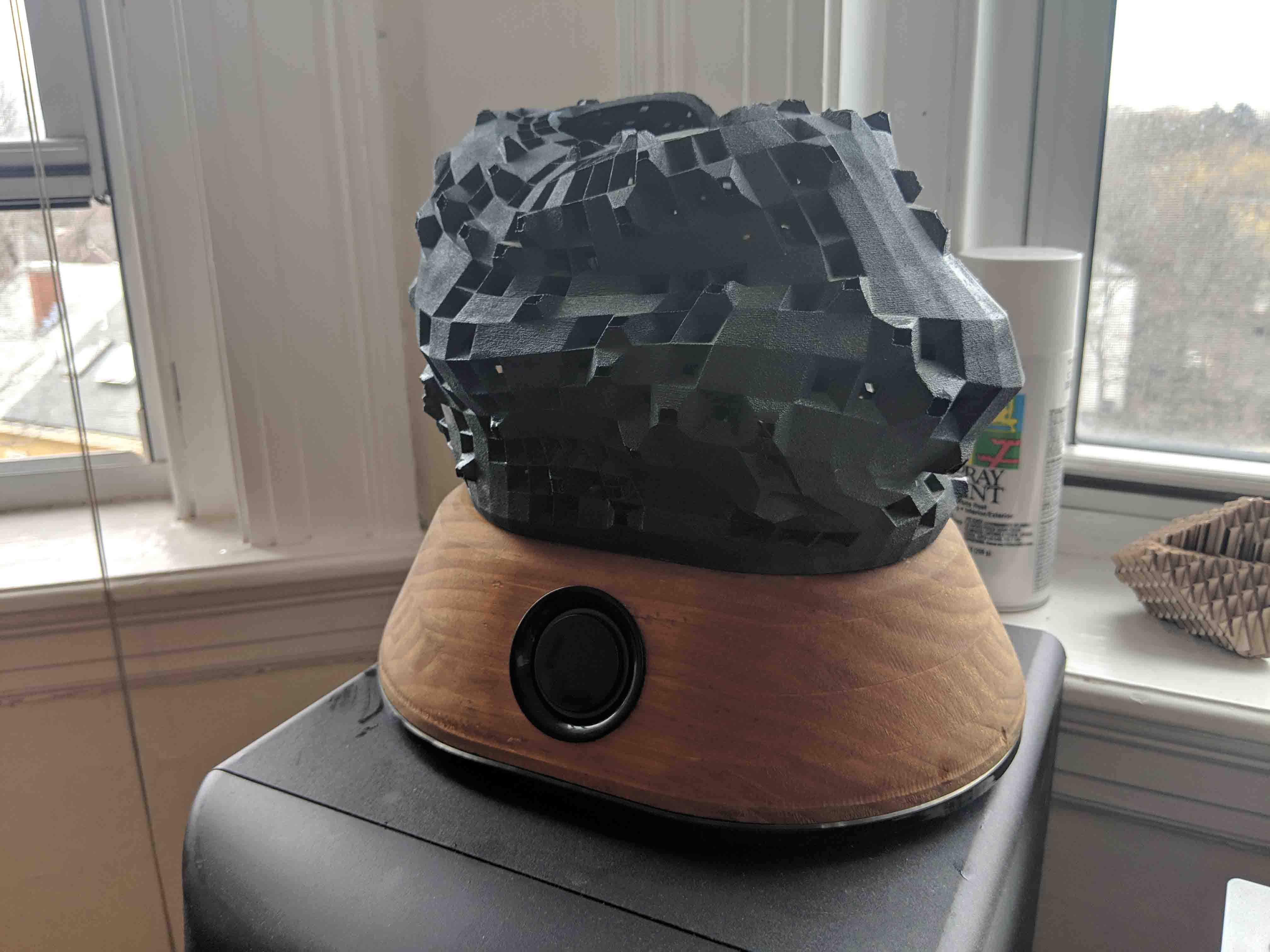
And finally, the end result! The speaker is finally complete!
...and the view from behind!
Now that everything is complete, I wanted to take a moment to recap and go over what components of the project accomplish what. Since it's easiest to go through these in topics, I've split this final writeup into a bunch of headers!
What does it do, what is it for, and what came before?Inspired by my frustration with our redundancy and wastefulness when it comes to our electronic devices, this project sought to create a speaker system whose interchangeable sound cavity might cater to a specific genre of music. By allowing a user to change the cap for a different speaker cap, the unit ideally increases its use by allowing for greater genres to be played.
Given that I was recently shortlisted for the 2019 Lexus Design Awards for my ideas for this prototype, it became clear very quickly that I had to actually build this thing if I still have a chance with the competition (I’m still waiting to hear back).
As I wrote previously, I had started plans for this project in undergrad, but had never built or experimented with it, aside from some plasma cut brackets and an MDF enclosure prototype. As far as speakers with interchangeable sound cavities… it’s sort of a novel thing. Neocapitalism demands that we keep purchasing new devices…
What did you use to build it, where did you source your materials from, and how much did everything cost?Though the work I had put in before this class relied on some robotics (the metal brackets were plasma cut with an ABB robotic arm) and CNCing (the MDF prototype was milled on an Osrund at Carnegie Mellon), much of the methods for construction were done at Harvard.
$60: For the base, I sourced some spare soft pine and wood glue, and used clamps to glue a bunch of stock together after I had planed them at the GSD’s wood shop. Because I was happy with the MDF prototype and its tolerances, and in light of me saving my developing designs in Rhino, I could quickly mill the pine with the GSD’s Osrund CNC.
$0: The majority of the electronics are salvaged from two Logitech computer speakers, as well as the main control knob for volume.
$0:: I found some extra orange LEDs at Harvard’s shop, and used all components for my own designed boards from shop, as well.
$60: The black and clear acrylic were salvaged from extra sheets I found in the GSD trays near a desk. I Venmoed a kid very little for them.
$0: The speakers were leftover from some non-branded computer speakers that I found on a giving wall.
$110: And finally, the 3D print was previously printed at Carnegie Mellon with the powder printer, and set me back about a bit.
What's the breakdown of skills used?$175: Total cost wasn’t too bad, but I was very lucky to use everyone’s facilities and parts. Grateful for Carnegie Mellon, Harvard, and MIT.
This project couldn’t have been completed without the resources at MIT and Harvard, as well as the skillsets learned through this class. Here, I wanted to take some time to go over how everything I learned got split up into the project.
2D Design: All of the acrylic necessitated laser-cutting, which was executed through the GSD’s FabLab. I relied on Rhino for this. Additionally, I used photoshop to manipulate most of my PCB designs.
3D Design: This project relied heavily on Rhino and Grasshopper - both to model the speaker base, as well as the L-System based sound cavity that I inevitably 3D printed.
Additive Fabrication: I relied on 3D printing for the sound cap. Specifically, I used a powder printer at Carnegie Mellon’s dFAB Lab for this.
Subtractive Fabrication: CNC milling on Osrunds at Carnegie Mellon and the GSD, and PCB milling on Harvard’s Roland Modela constituted this part of the project.
Electronics Production and Design: Though I relied on an Arduino NANO and a lot of salvaged electronics for most of the project, I integrated a simple PWM LED electronics board. The design of this board was done primarily in PS, as I worked off of Neil’s board but changed its dimensions to fit the form-factor of my speaker base. I also added a 2x2 header and replaced the direct connection between the LED and the board.
Microcontroller Interfacing and Programming: While I relied on Arduino as my IDE for most other projects during the semester, I used the terminal to communicate with my micro controller while programming. Interfacing is pretty simple with this specific board, as it just turns on and off whenever it receives a signal. The rest of the interfacing (with the speaker, that is) is done through physical interactions with the volume knob and the lifting/installing of the speaker cavity, itself.
System Integration and Packaging: All the electronics are meant to be concealed within the speaker base - it’s for this reason that the inside of the speaker is hollow. The only exposure I wanted was for the electronics for the speaker wires/top. Packaging is clean with just wood, black acrylic, and little rubber feet. Systems integration and packaging was pretty integral throughout the whole process, as it dictated much of what the speaker actually looks like. It was the most fun part to pursue.
All in all, though I feel that there’s still much I wish I could’ve tackled (such as internal battery supplies, bluetooth…), I’m happy with how the project touches on all cornerstones of the course.
What was the point?As I touched on earlier, this project stems from my frustrations surrounding redundancy and overabundance in how we approach our electronic (and daily) devices (and machines). Coupled with the fact that I am trying to push this project for the 2019 Lexus Design Awards, I wanted to create a prototype that I was both proud of, and that I also learned from. Most critical to me was to exercise many, if not all of the skills we learned in HTMAA.
In this way, this project literally serves as a device (pun intended) to explore new ideas. I also admittedly just really wanted to make something pretty. There’s something to be said about an esoteric art-like object sitting on a table, especially if you built it.
Was it a success, and where is this project headed?To me, success can be measured with a three-part metric.
The first involves how I feel about the project - which is strong. As a design student, the most important thing to me is making something that works, while looking novel and inviting. The materials I used, and the end-finish, is something I’m proud of.
The second involves the course expectations - which asked us to integrate all of the skills we learned. While I wanted to do just a bit more with the speaker, I still feel like it touched on and celebrated almost all parts of the class, while really pushing systems integration and packaging and an overall strong aesthetic.
The third involves the LDA 2019, which is obviously out of my hands until mid-January announcements. Though I don’t think this project’s outcome ought to be affected negatively based on the outcome, I certainly would be proud of it more if it places as finalist standing.
Thanks for reading along! Please reach out if you have any questions or concerns.