When my roommate and I moved into our Cambridge apartment this summer, we were dismayed to discover that our chandelier was missing its glazing panels. As such, it became a priority of mine to address this.
This assignment provided a perfect venue for me to experiment with a modular hanging system, whose arrangement could be altered if desired. Because of my sensitivies to lighting concerns, I thought that transparent/reflective acrylic would serve as a great experimental material for the project.
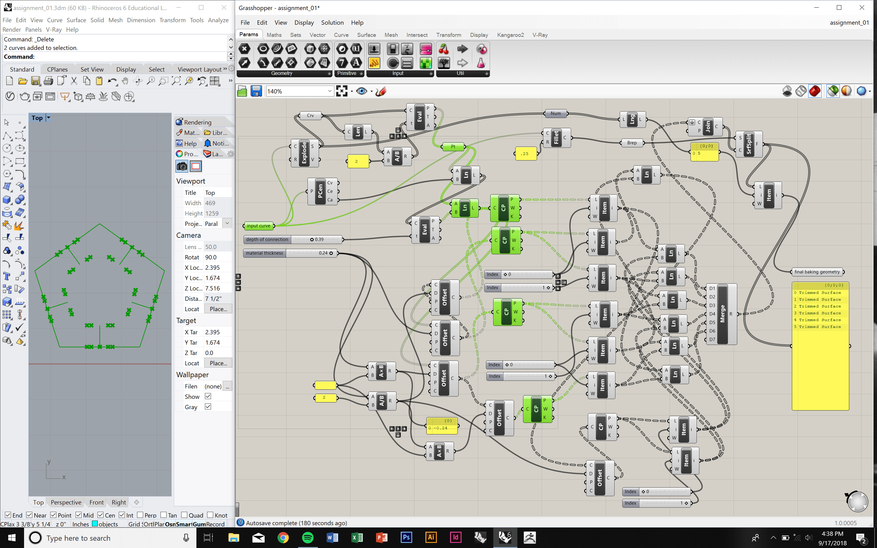
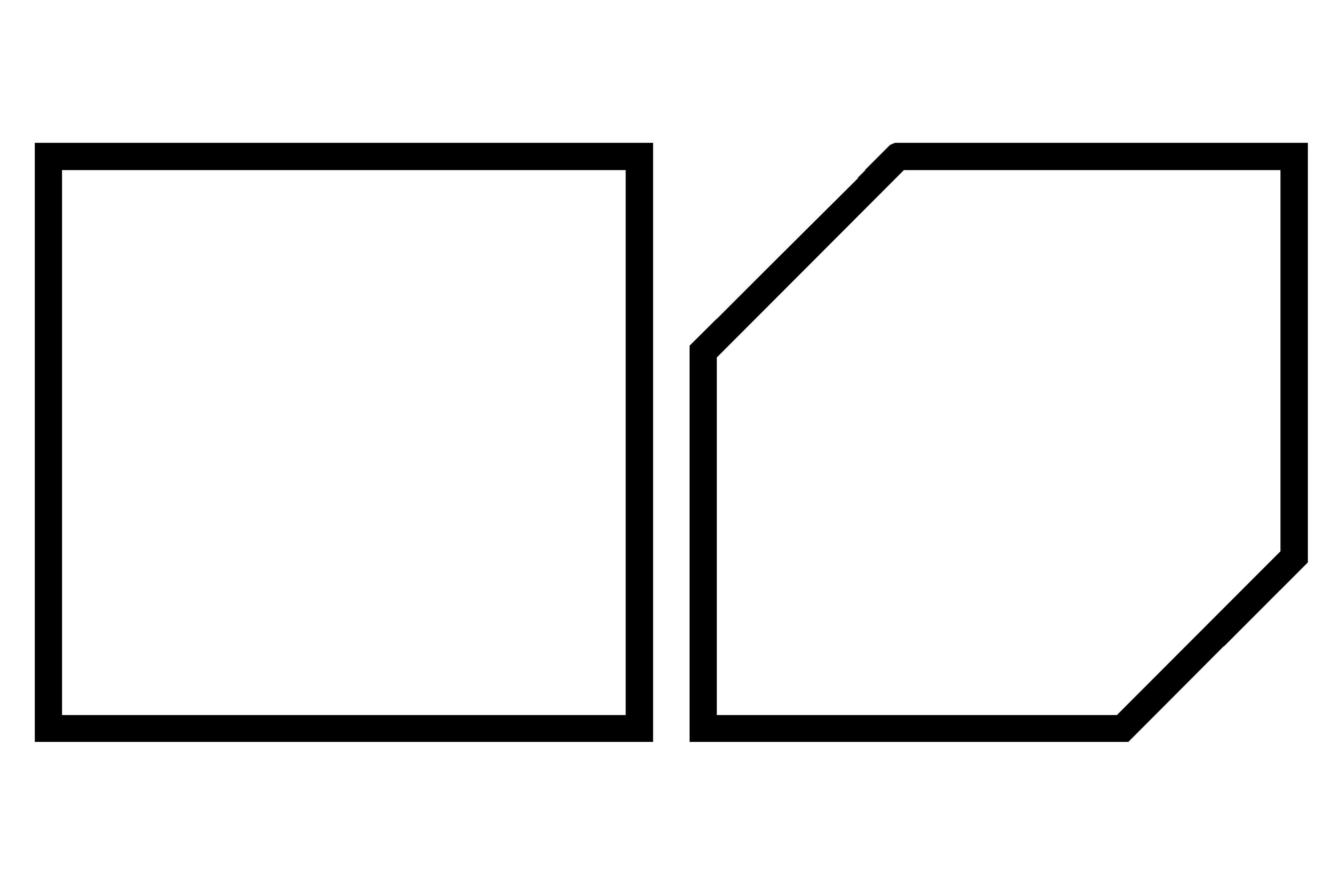
I wanted to create a Grasshopper script that could take any polygon as an input curve, and output a bakeable object whose depth of intersection and width of cut would be parametrically altered. Here, we see a pentagon as an input, but I also ultimately outputted a square, hexagon, and octagon.
I began by exploding the input polygon into its verticies and curves. From there, I was able to select midpoints of each curves, and define parametric offsets from these points that would allow a user, through sliders, to control offsets.
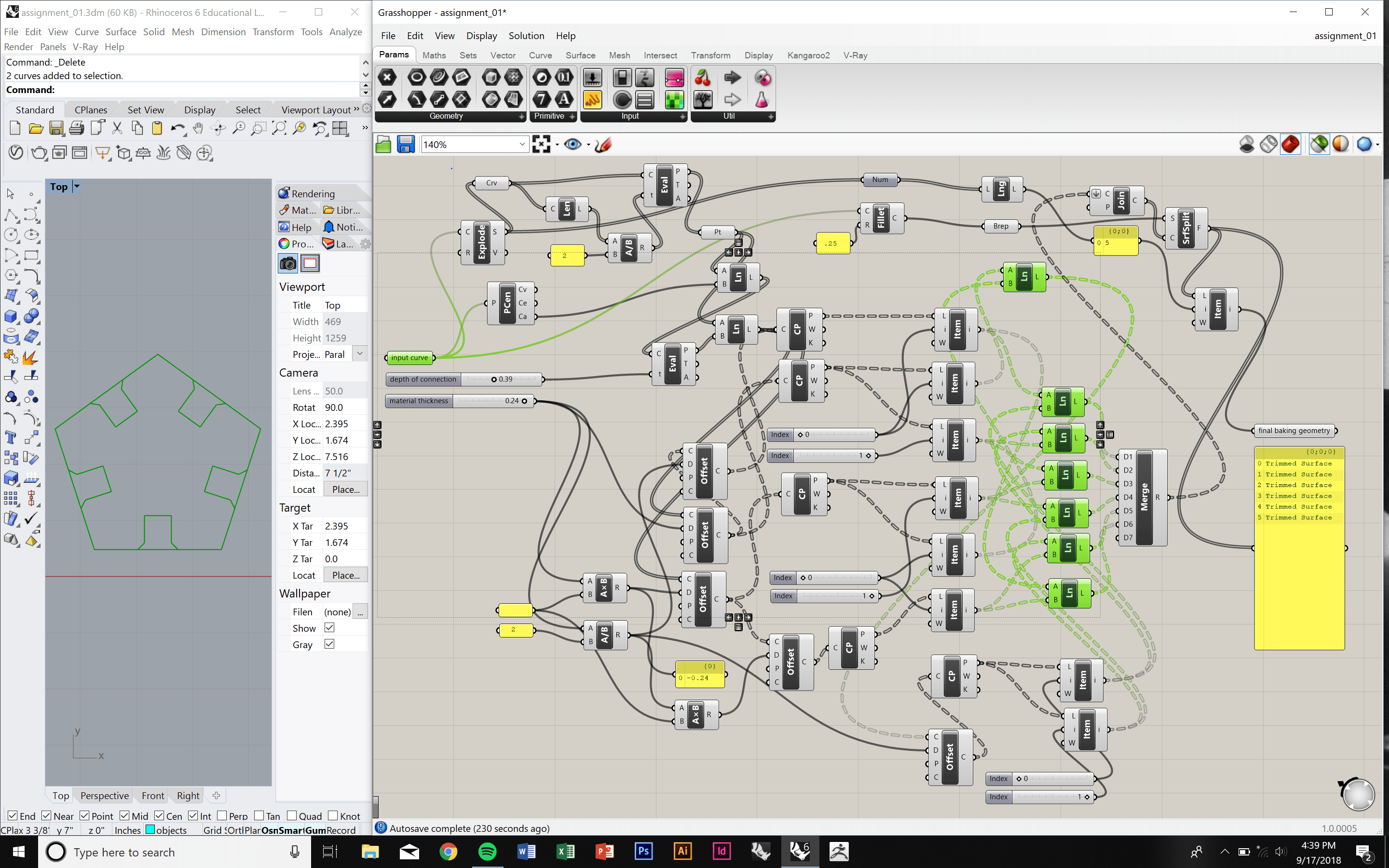
From there, I manipulated the code so that it accomodated for a chamfered edge. This chamfer aimed to ease connection processeses, and reduce any stess in the brittle material that we all know is acrylic.
List structure proved to be a challenge in this step, as I was having issues with flattening my list of points that I wanted to connect. I ended up developing a somewhat convoluted series of steps, involving itemized lists and complex merging. It works, but it could be cleaned up.
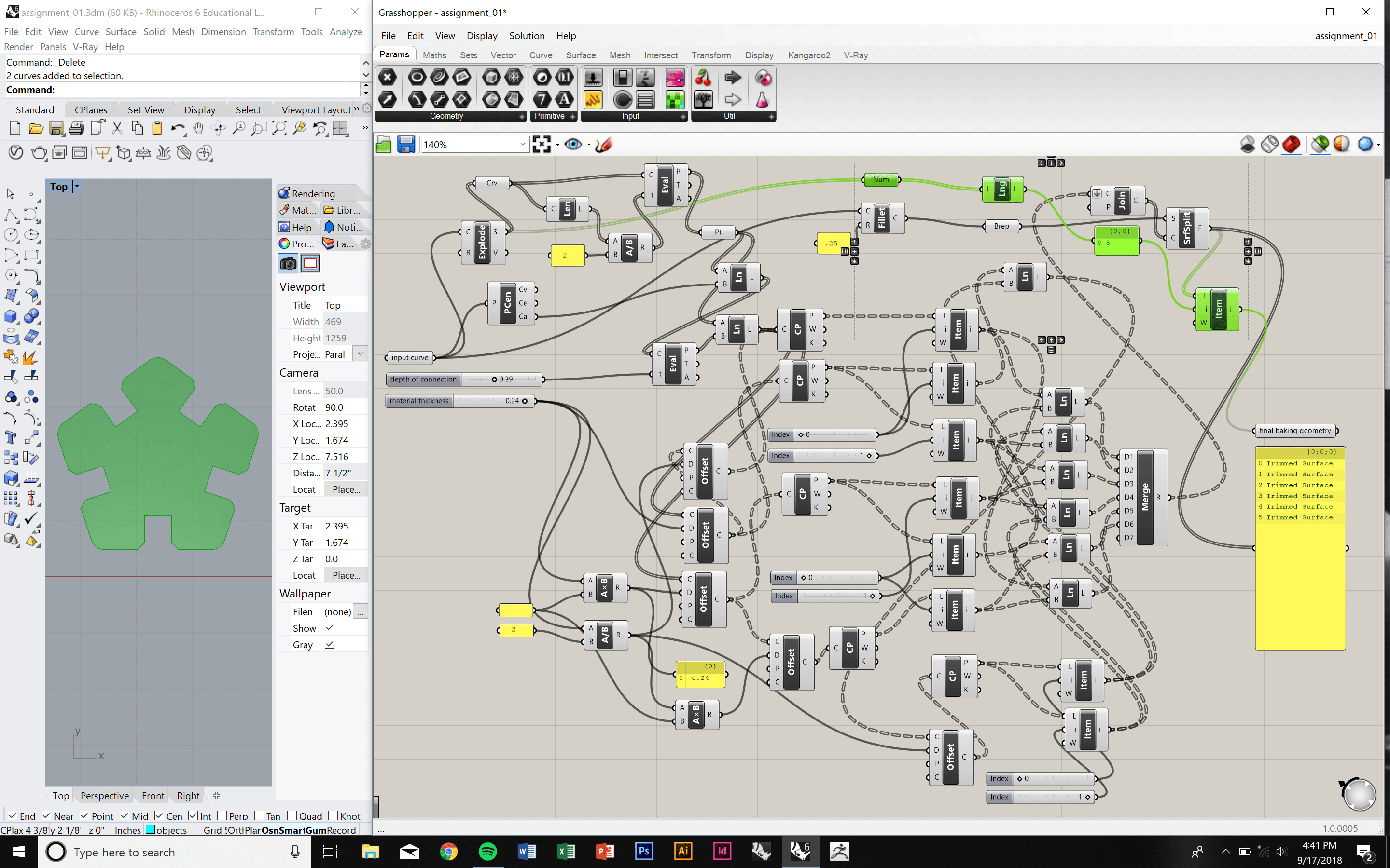
Finally, I trimmed any overlapping geometries to obtain the object that I'd inevitably bake. This part of the script turned out to be smarter than I thought it would have been, as it's capable of trimming out X amount of objects from any object. In other words, it knows to trim 6 objects out of a hexagon, 8 out of an octagon, and so on. This was made possible by isolating the number of sides of the polygon, right after exploding it, and converting it into a numerical, non-data value.
This GIF shows the variations of thicknesses that can be produced. Currently, the slider is set to accomodate for thicknesses between 1/32" and 1/4", but this range could easily be changed.
As this GIF shows, the script also allows a user to vary the depth of overlap. Obviously, after a certain threshold, a cut too-deep would lead to collisions between pieces. The point at which these adjacent collisions could occur would vary, and depend on the input geometry. I haven't yet created a limiting factor for this, so that could be a great next step.
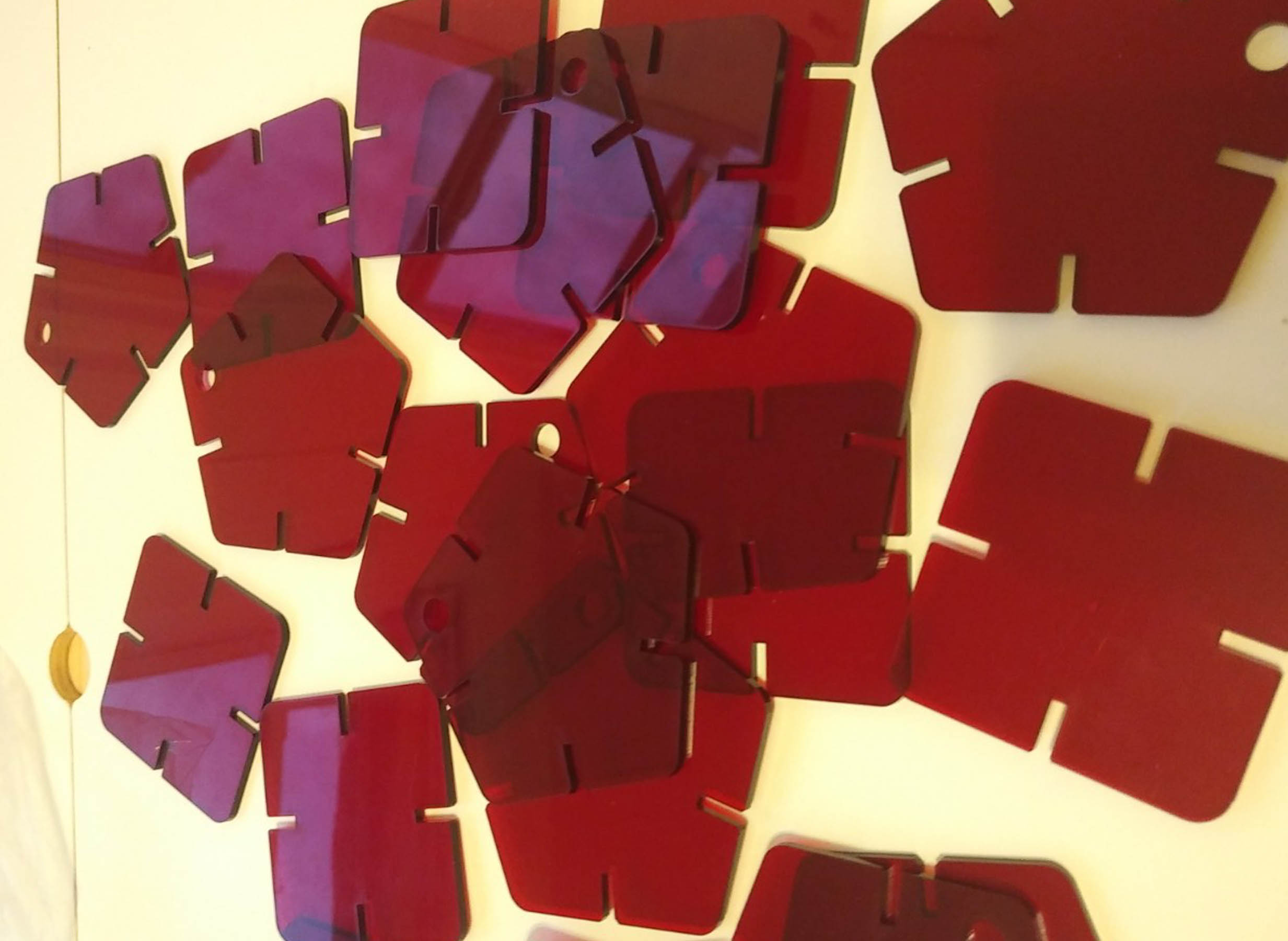
It was then time to cut. I used the same laser settings that we had in our group exercise - 95% power, 4% speed, and 1000% frequency - and a thickness of cut within the threshold that we had identified.
You'll notice that the pentagons have holes in them. This was done in light of my plan to start each dangling chandelier chain with a pentagon shape. Each object was around 2" across.
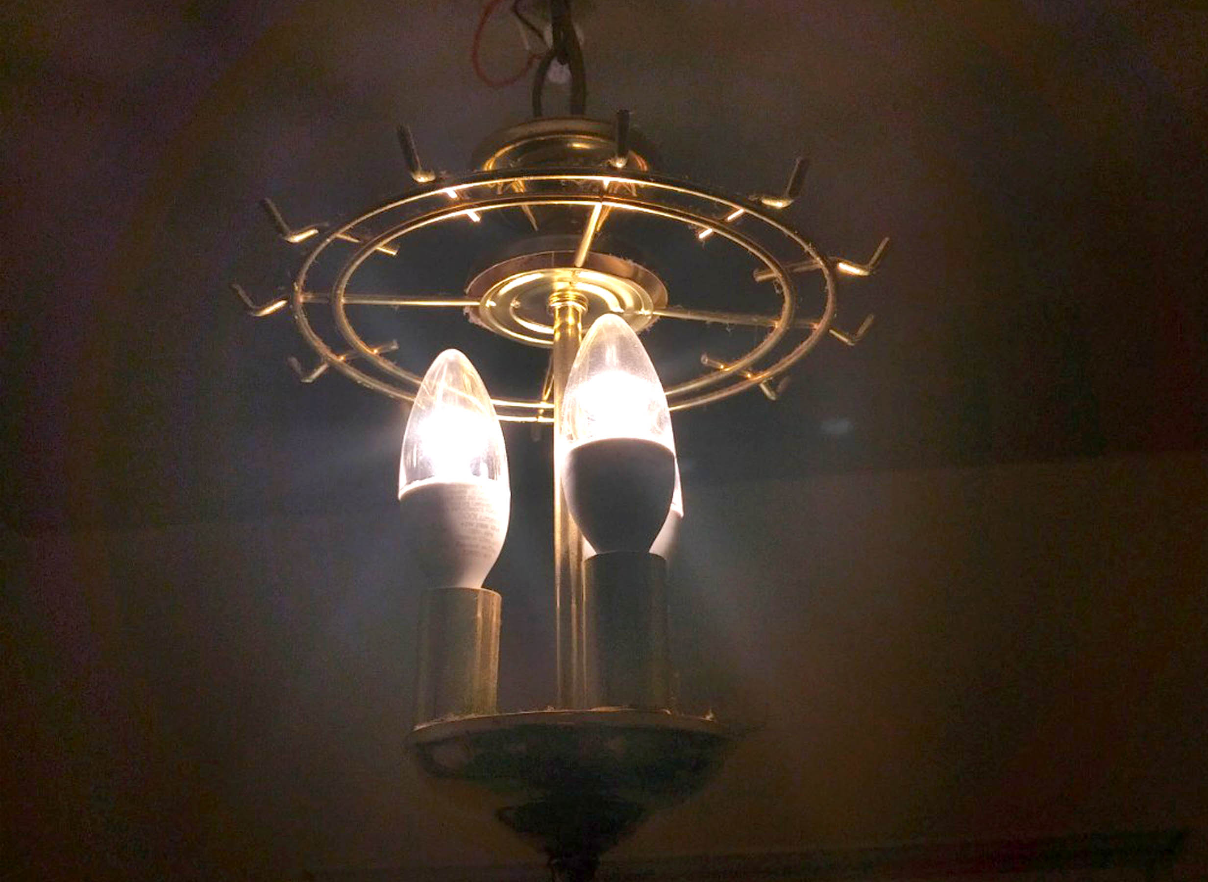
And so, the final product!
I do wish I had either more acrylic, had scaled down the size of the pieces, or had variations of transparent colors. At the current moment, the chandelier is rather... short. Still, in low light illumination, the shadows cast on the walls of our kitchen are quite nice, and I'm pleased.
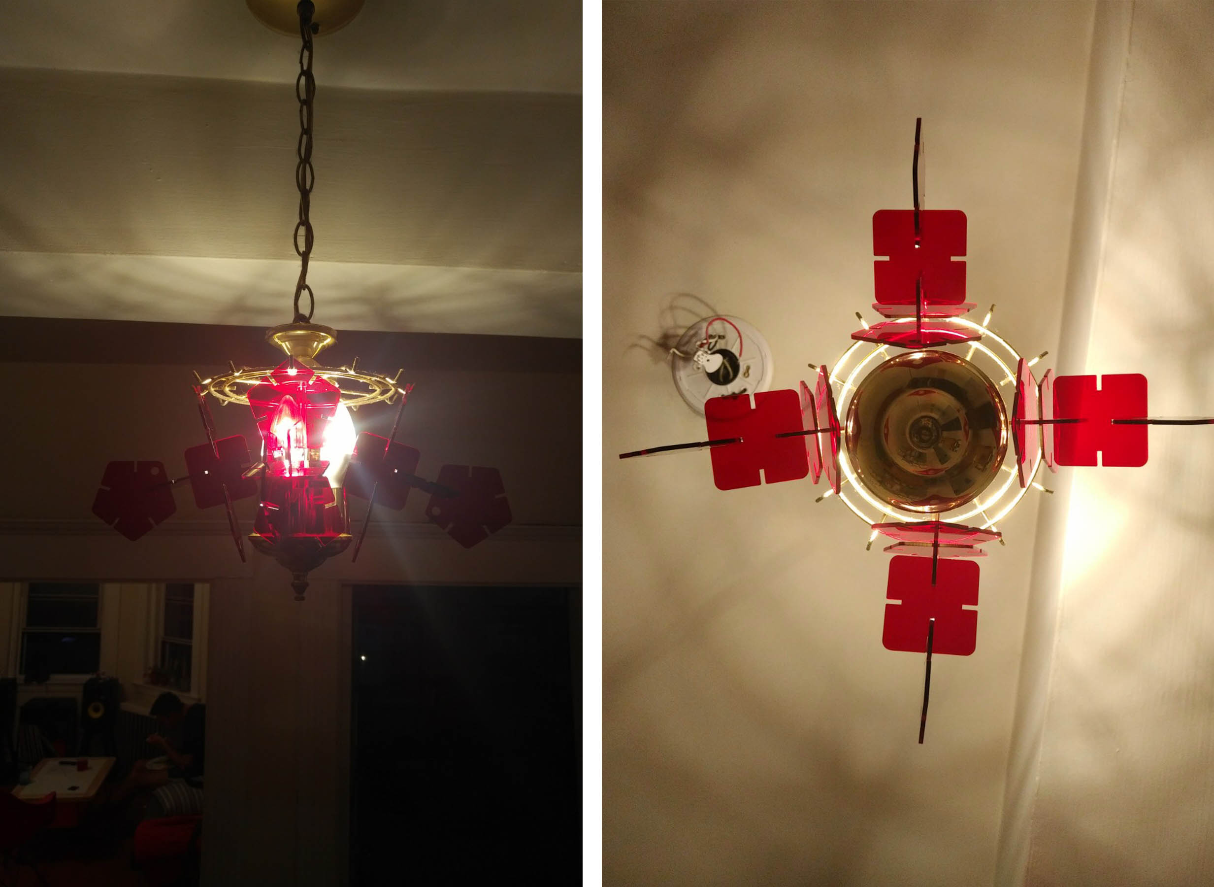
I would also hope to populate more of the hooks on the chandelier. As you can see from this bottom-up view, the four strands are a bit lackluster.
On a positive note, though, more material can be cut easily with the Grasshopper script. My roommate thought that 1/4" acrylic could reflect light more drastically, too, so that would also be a future direction I'd consider.
This week epitomized the reason why I so strongly wanted to pursue this course. Never before have I ever made my own electronics boards. Given my interests in rapid prototyping and Arduino based coding, this has always been exciting for me. Finally, I’ve been able to dabble with it!
Thanks to a stellar student who had already taken this course, we were given a circuit design in PNG form. Since we’ll be looking back at PCB production and design at a later week, we didn’t have to worry about design methodologies just yet.
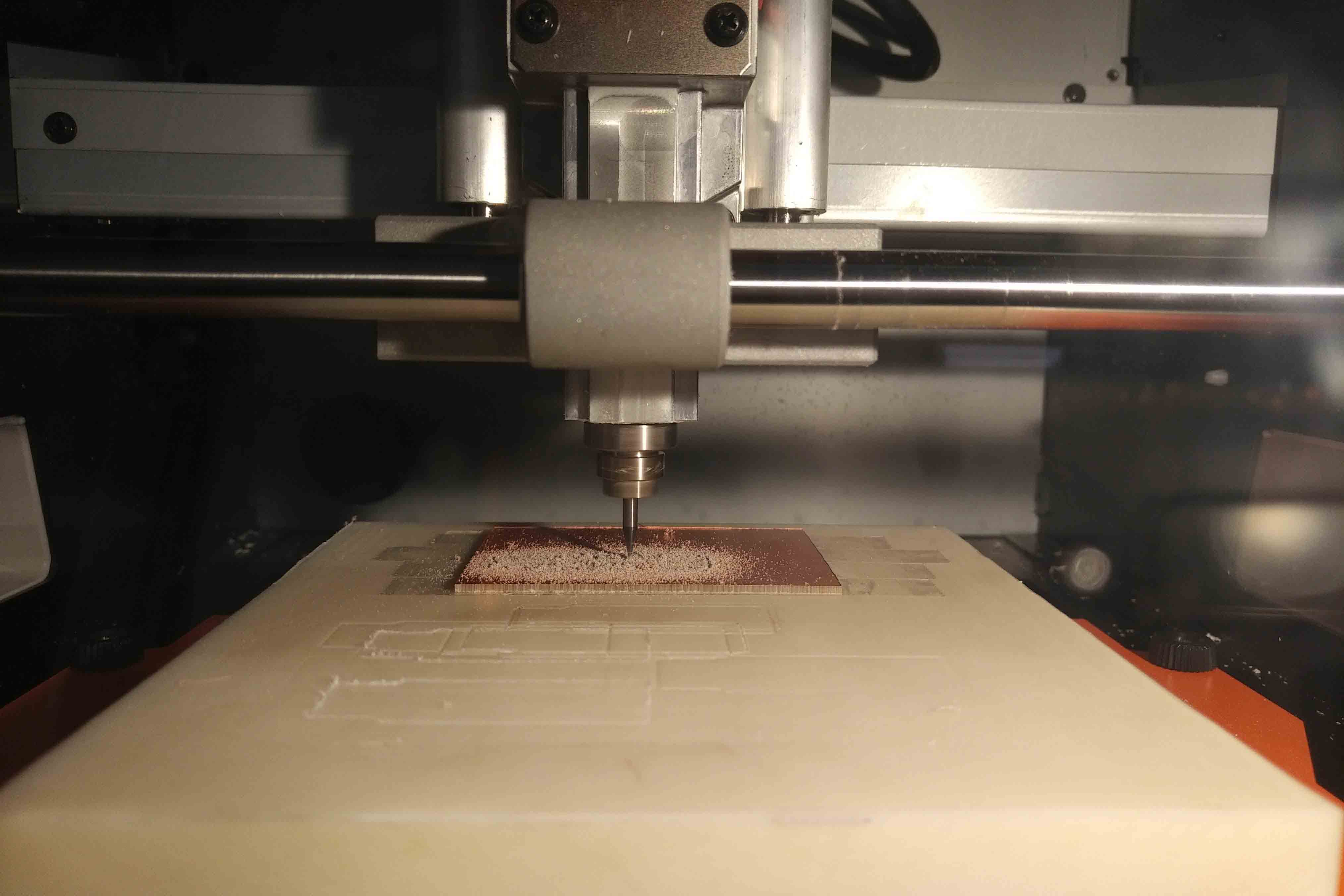
As such, we were all able to dive straight into milling. Be sure to check out the "Group" section of my page to get details on how we characterized the PCB production process, and learn about the minutia of actually milling PCBs.
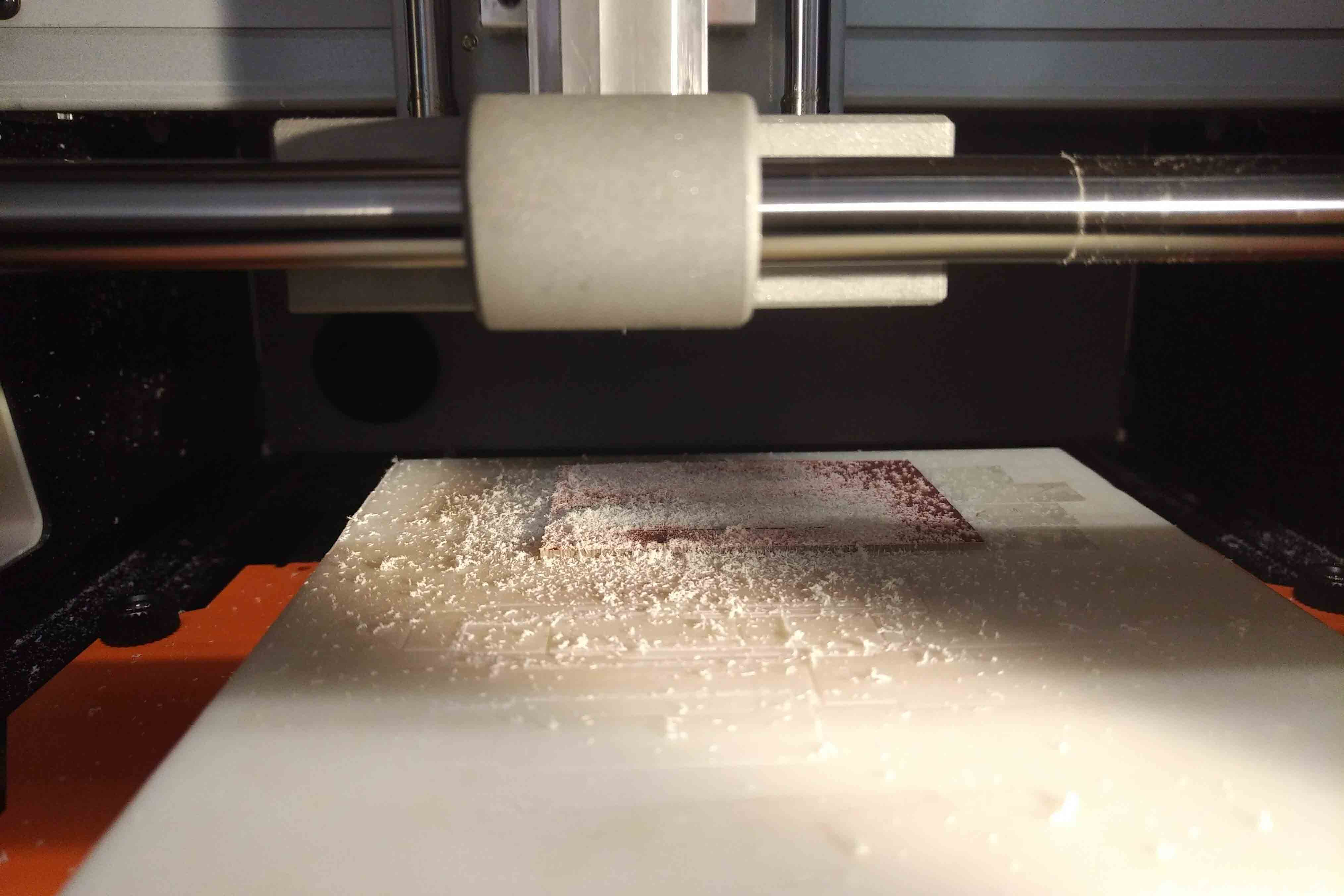
After both mill jobs were complete, I scraped the scrap material and PCB off the spoil board with a spatula and cleaned up the powdery residue left over from the operations. I used a knife to take off any excess sticky tape from the bottom of the PCB, and used some steel wool to sand off any burrs.
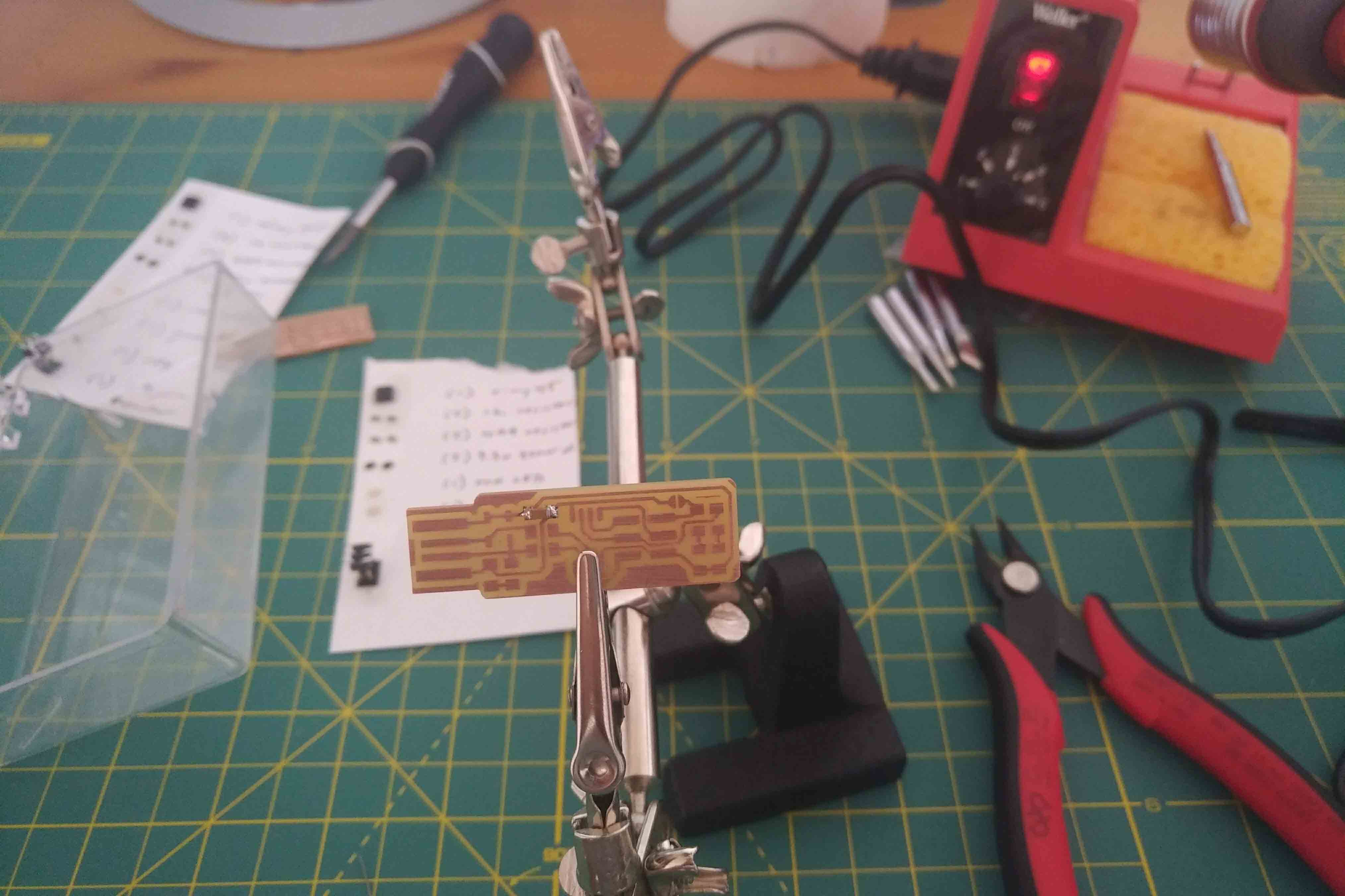
Then it was time to actually solder my components on! I have some soldering experience, so I wasn’t too worried about this. Mostly, I was frustrated about my tremors in my right hand, as they made soldering a bit difficult at times. Nonetheless, after organizing my parts on index cards and preparing my soldering station, I got to work.
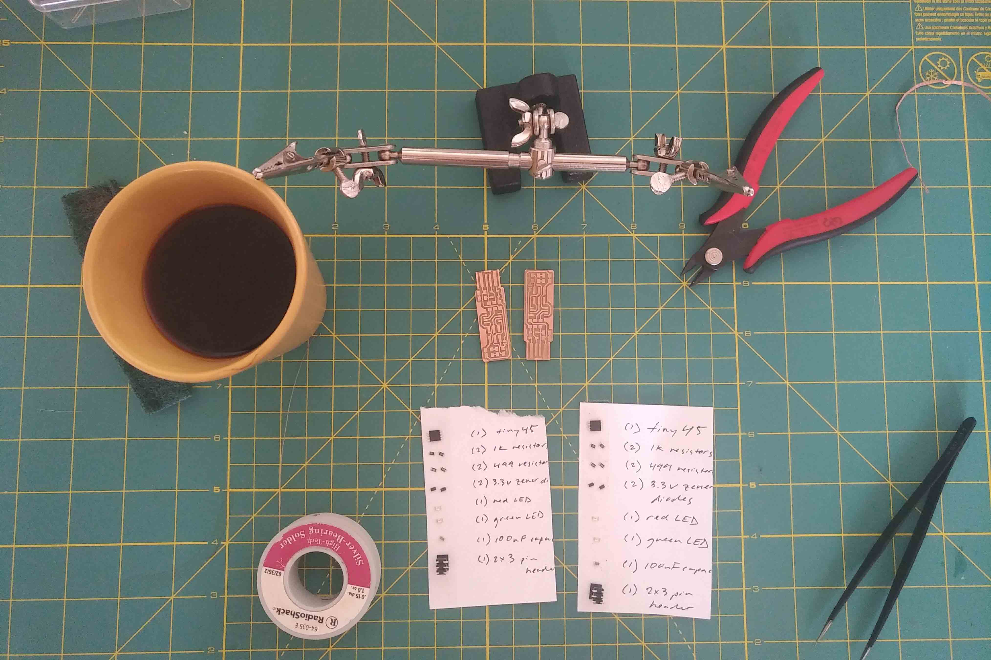
I simply followed the wiring diagram provided by the aforementioned student, paying special attention to the directionality of most of the components. For example, the “Tiny45” processor has a little dot on one of its corners, which is indicative of its proper orientation on the board. Similarly, the LED’s had little green strips on one side to indicate directionality. I also added some extra solder to the USB leads to make connection with a computer much easier. All in all, the board took about 25 minutes to solder.
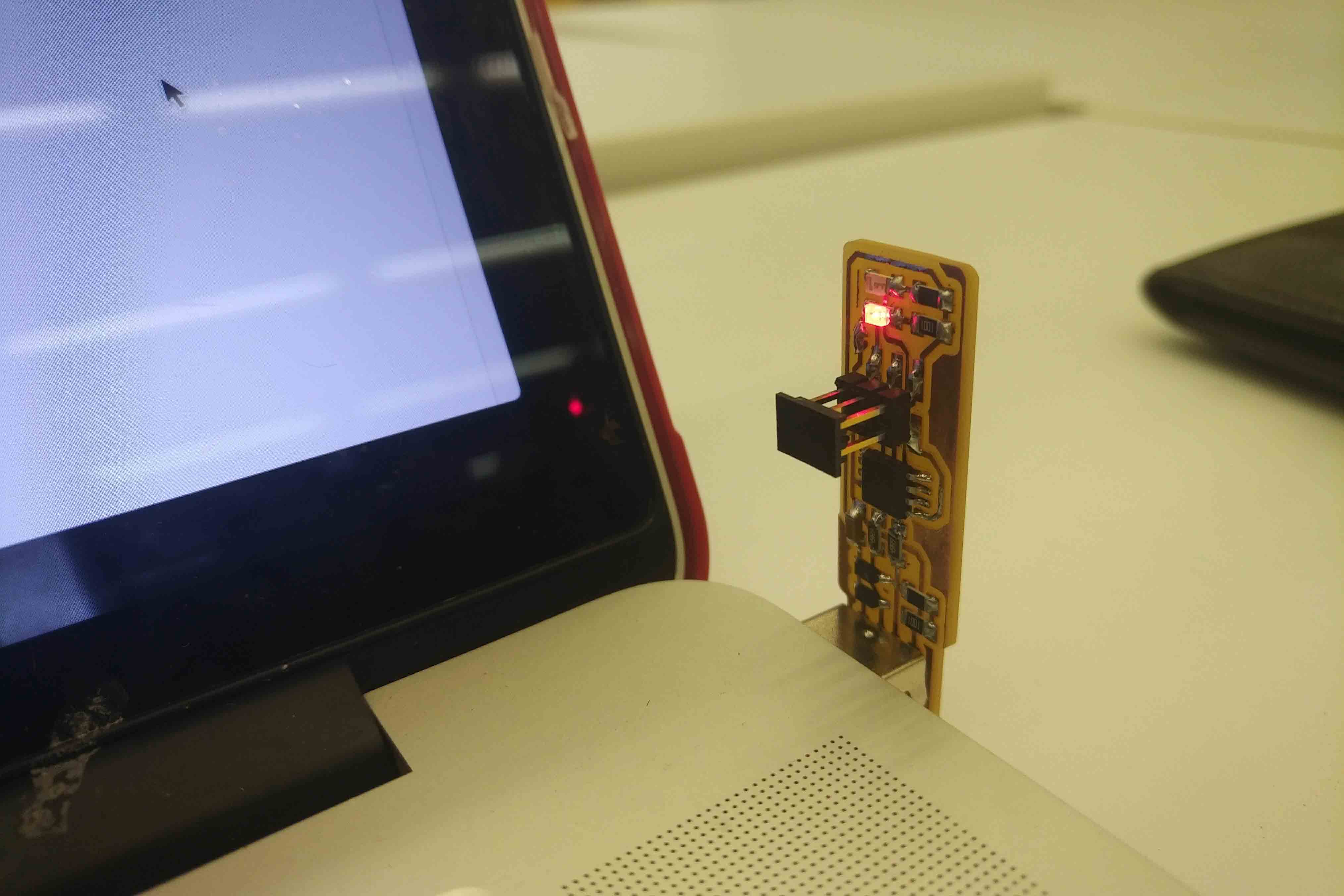
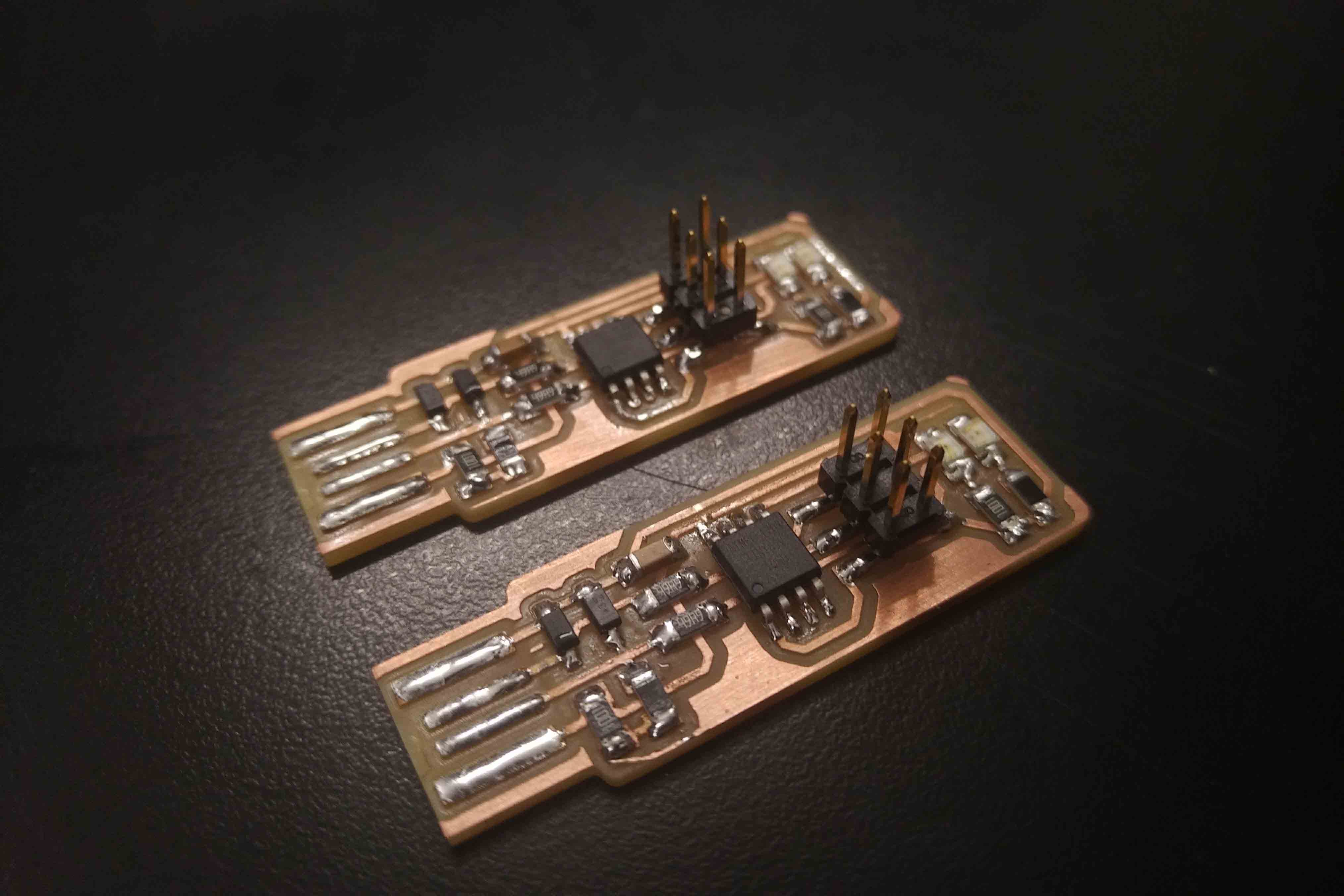
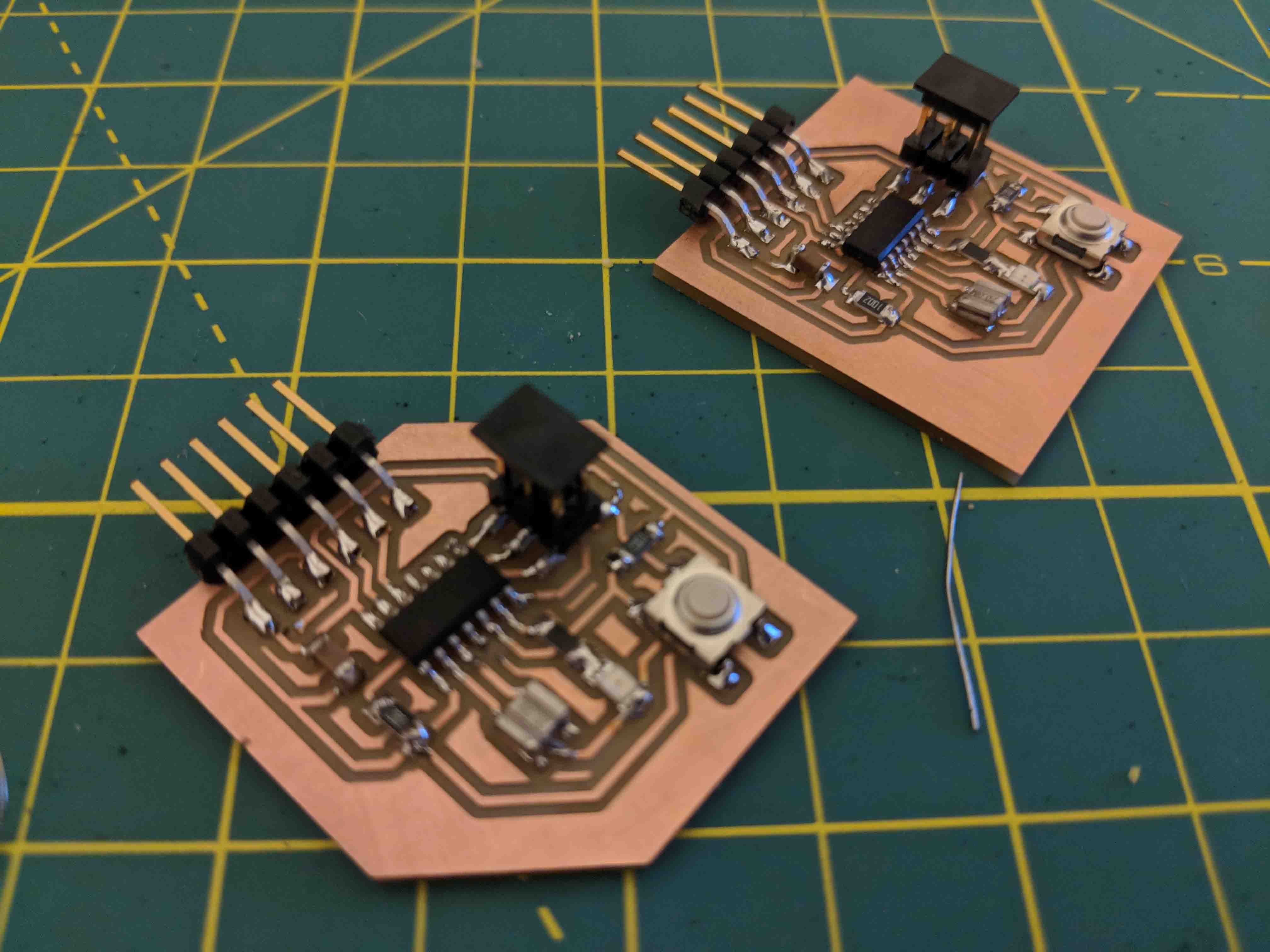
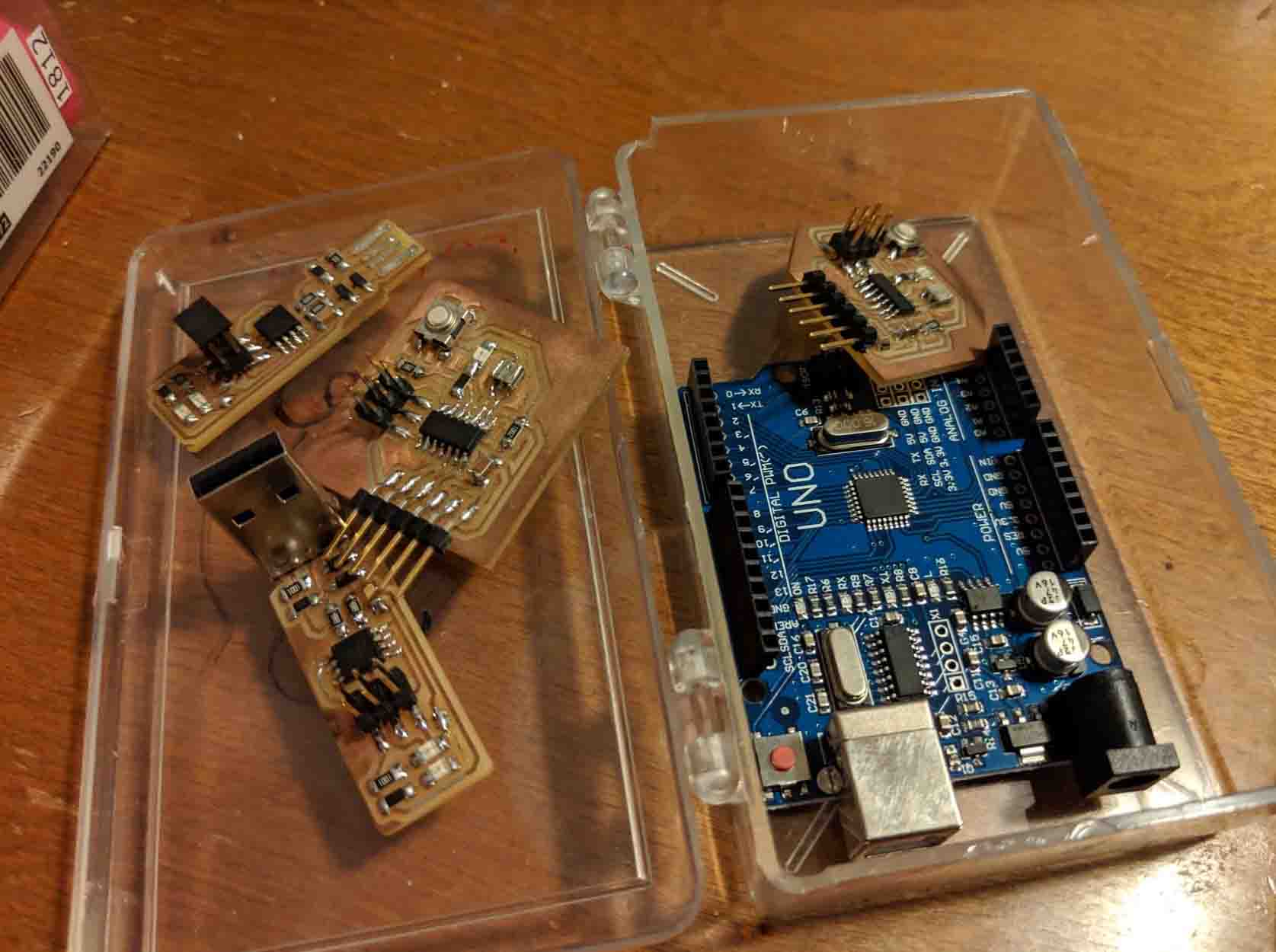
Here you can see the boards that I finished (I made two in case I screwed up one of them, but they both ended up working just fine).
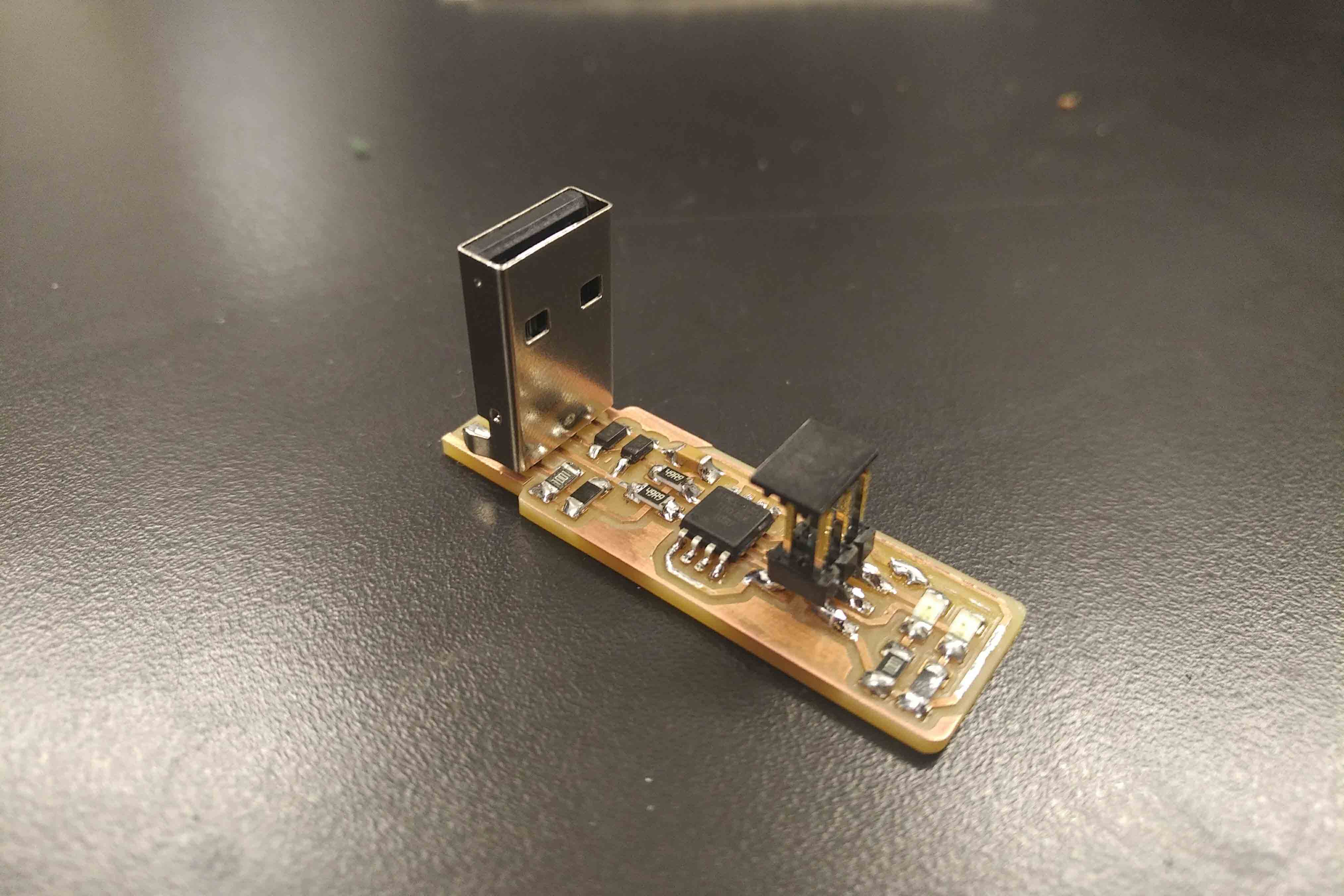
In the end, I decided to also solder on a USB hub attachment to one of my boards to make connection easier. I found that even though I added solder onto the USB leads, connection was extremely sketchy. This USB hub addition really helped.
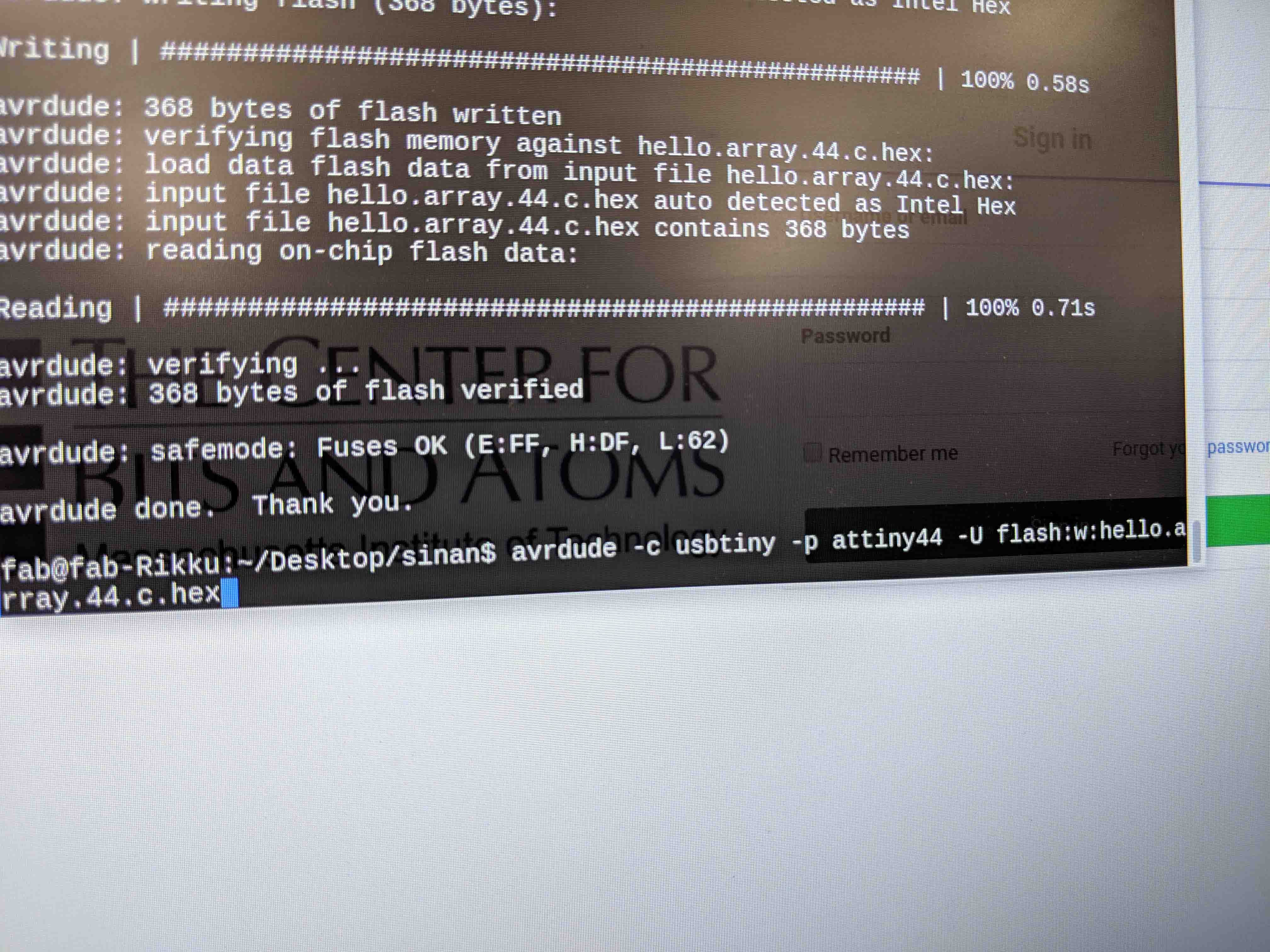
Unfortunately, despite trying to program my boards for quite some time, I couldn't get past Brian's step of creating the ".hex" file. In other words, I was able to work remotely from my Mac up until this step - thereafter, I struggled to connect with the board. I kept getting errors that told me that "usbtiny" wasn't able to be found.
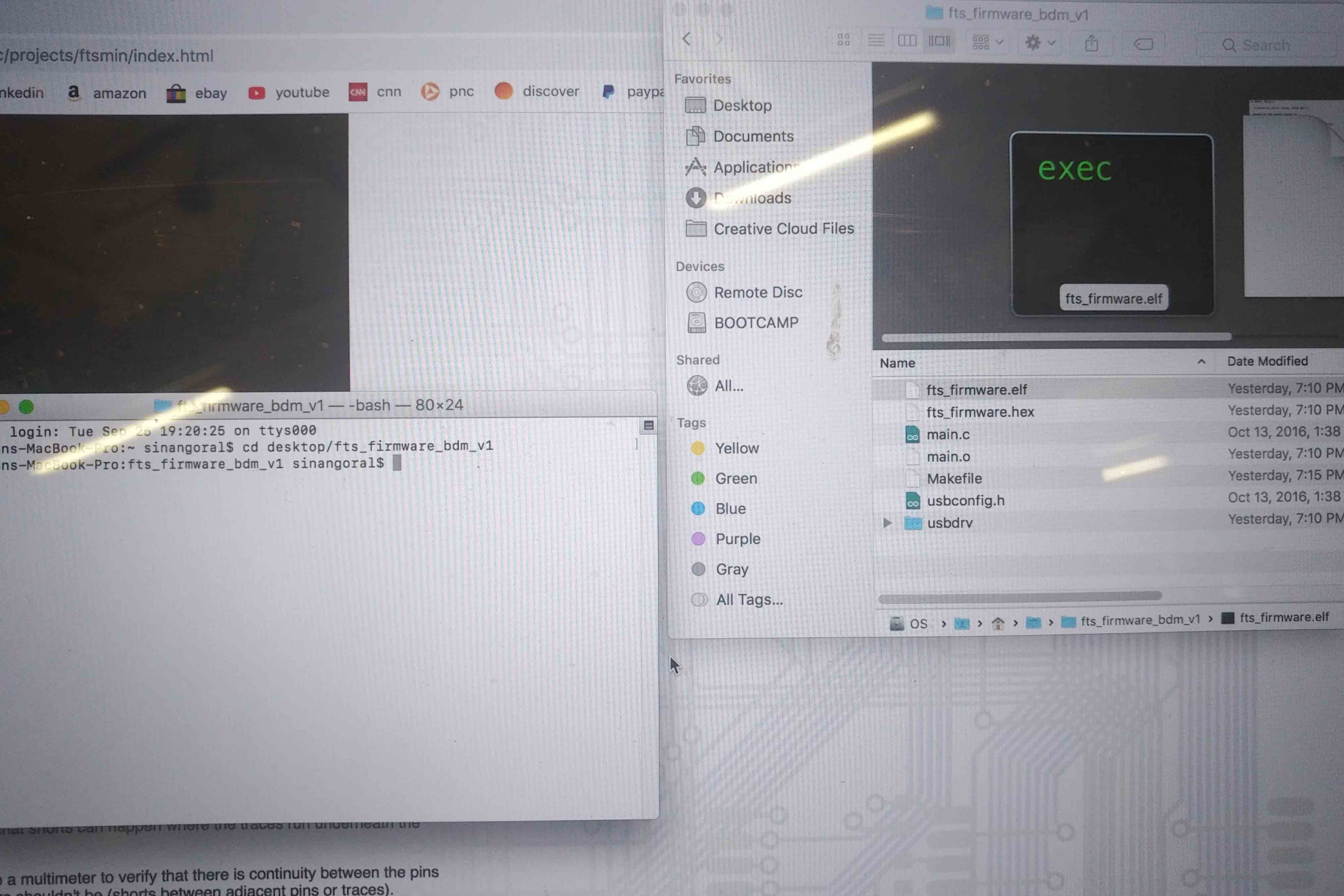
At this point, I think the culprit is the fact that both my USB hubs on my laptop run 3.0 speeds. I was hoping to find a dongle that converts from 3.0 to 2.0, or to at least find an older-school computer to do this on, but couldn't seem to find one. Excited to debug this and find a work-around in the next several days!
This week, we set out to 3D print any object that couldn’t be made subtractively. Because I have a lot of 3D printing experience already, I set out to fabricate something I had not yet tackled, but have always wanted to do - a 3D printed textile-like fabric pattern with interlocking, tessellating pieces.
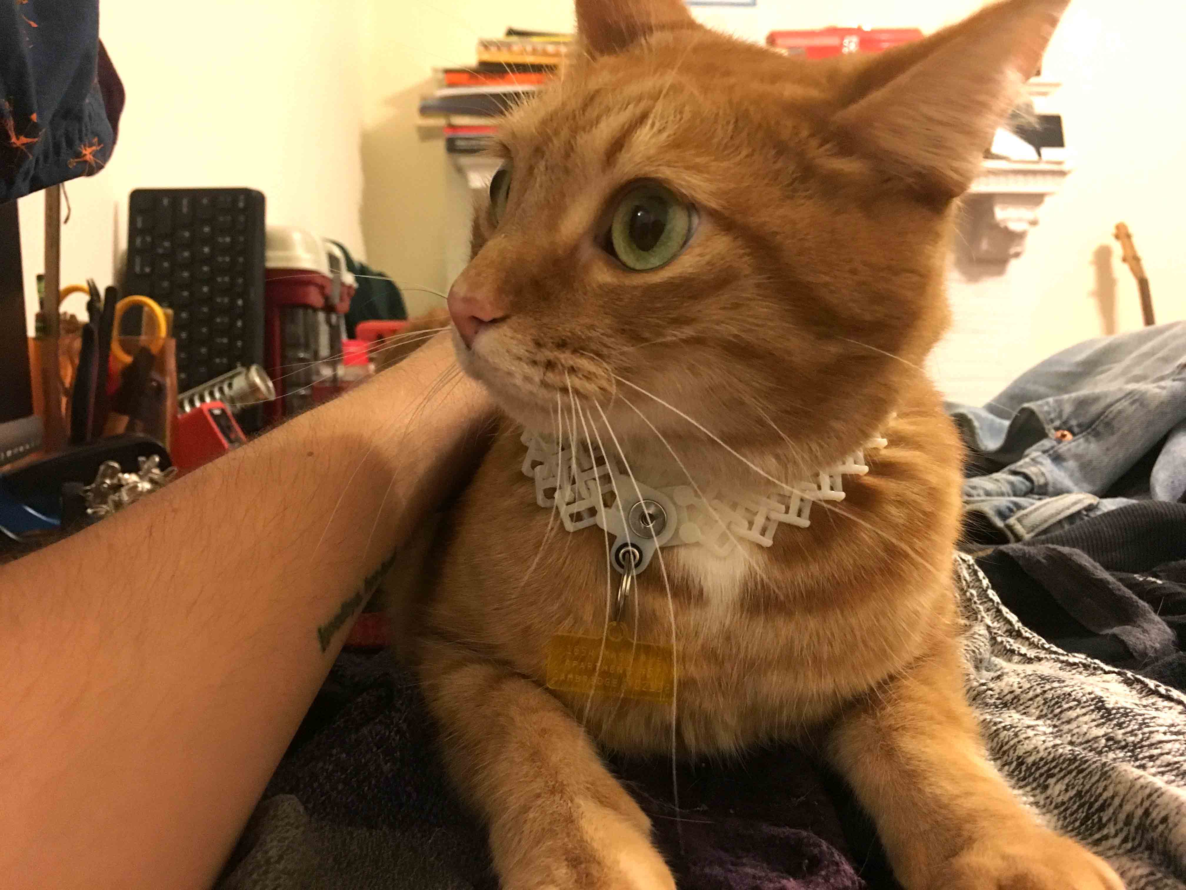
Continuing the DIY mentality I’ve adopted throughout this course, I thought that I could try to design a collar for my cat, Jack. His vet thinks he might have an allergic reaction to nylon, which is oftentimes the material inherent to most kitty collars. As such, I set out to make him a 3D printed, magnetically snapping collar. Here’s the eventual result!
The first design I worked up didn’t end up working, but I’ll walk you through it nonetheless.
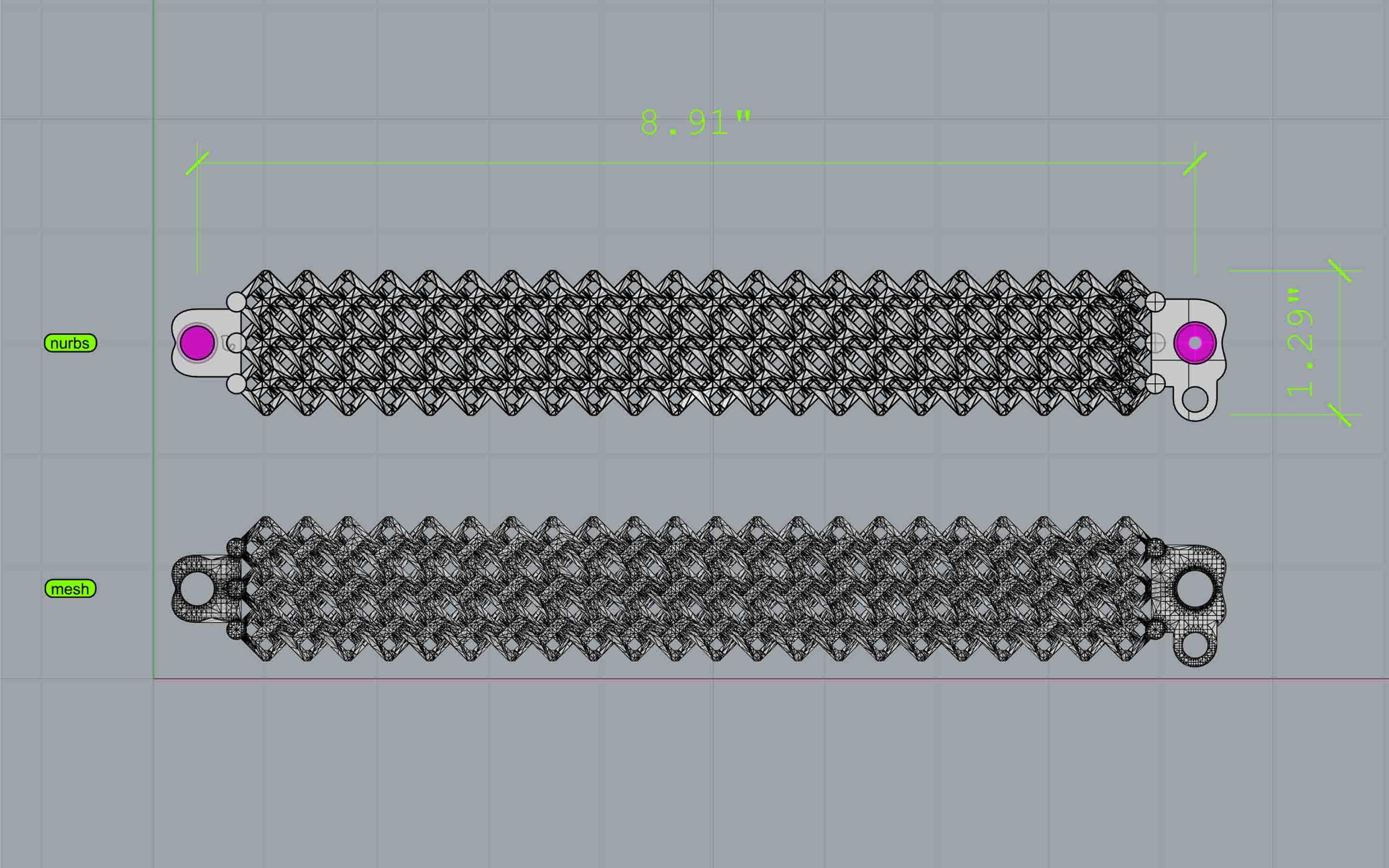
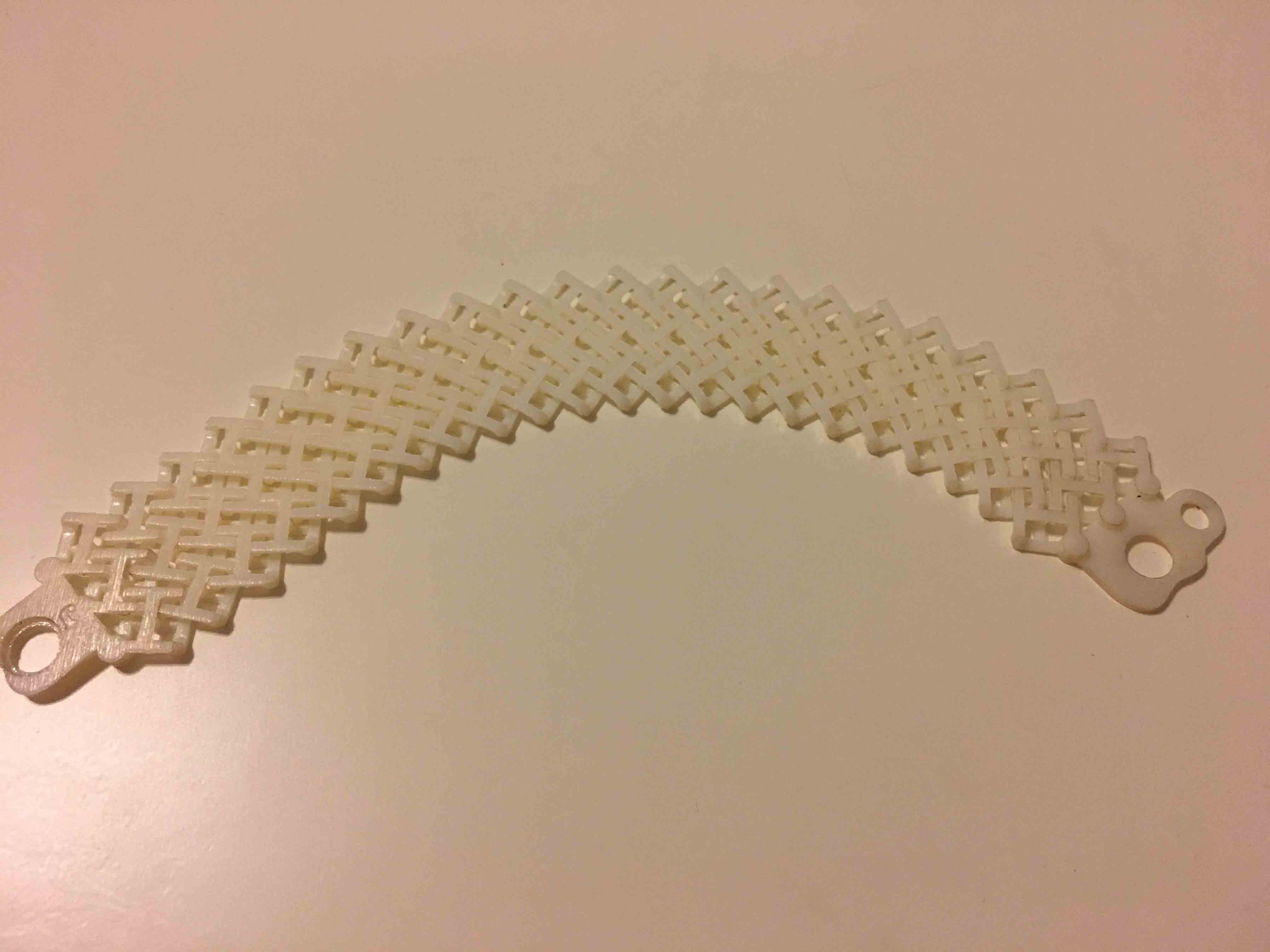
I first designed an interlocking chain-like object - one that when replicated, creates a chainmail like fabric. As you can see here, the object had three rows, which ended up being too thick for Jack’s tiny neck. Still, it was helpful to print and see, tangibly, what to fix.
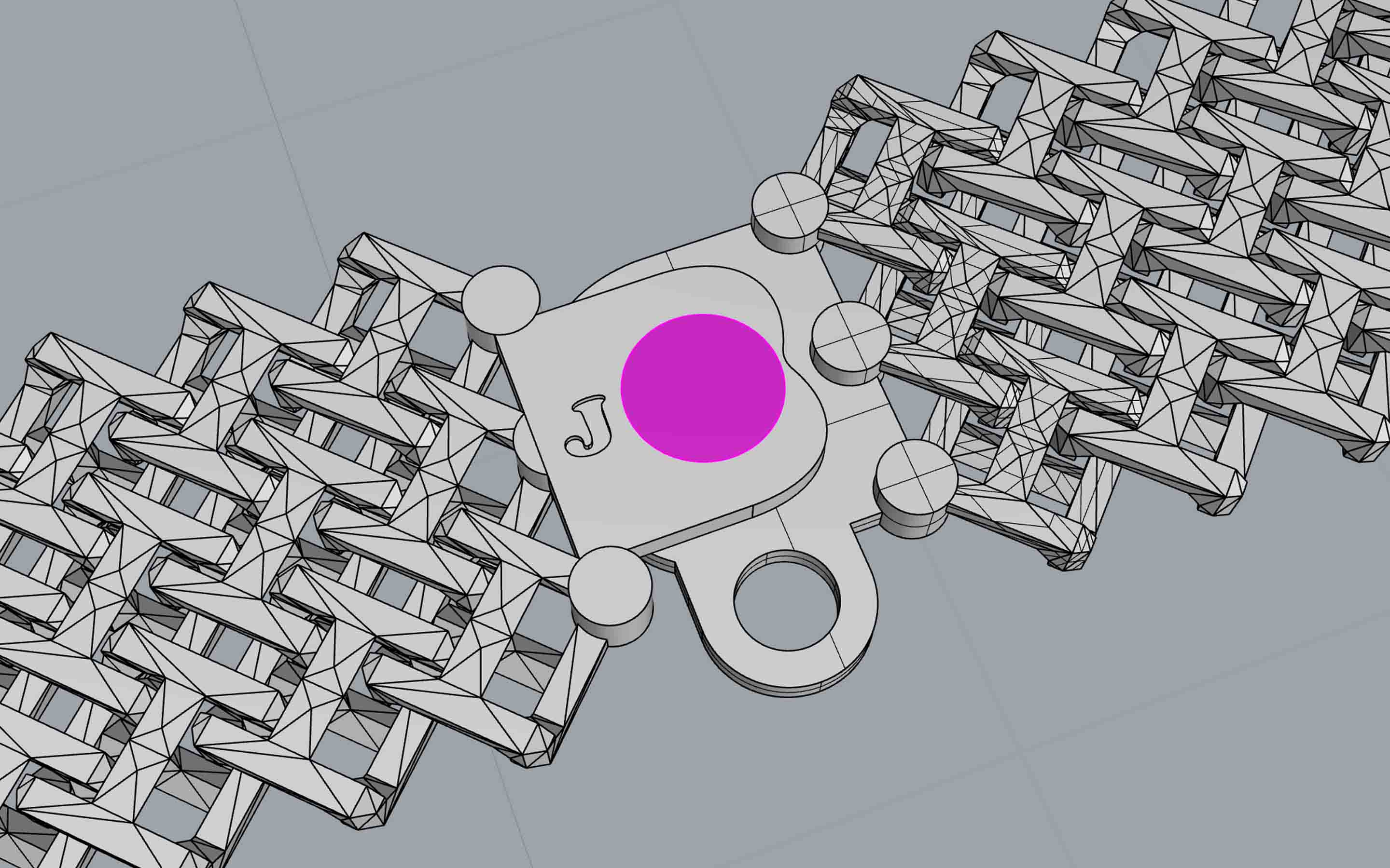
The design incorporated two overlapping pieces which had earth magnets inset into them. I somehow got the snug-fit tolerance right on the magnets on the first go. Speaks either to my previous 3D printing experience, or just damn luck…
After printing on the GSD’s Objet ABS printer, I had to put Jack’s collar in an acid bath. Normally, this process would take several hours, but I removed much of the gooey support material with a knife, and the whole thing was clean within about 50 minutes. I sprayed the print off with water, and ended up with what you see below.
Once I saw what I was happy with and what I wasn’t happy with, it was super easy to reiterate and reprint. I simply removed one row of links, added two more columns of links (to give Jack’s little neck a bit more room), and for fun, added “SNAP!” to both sides of the snapping side of the clasp. And now, Jack has a collar!
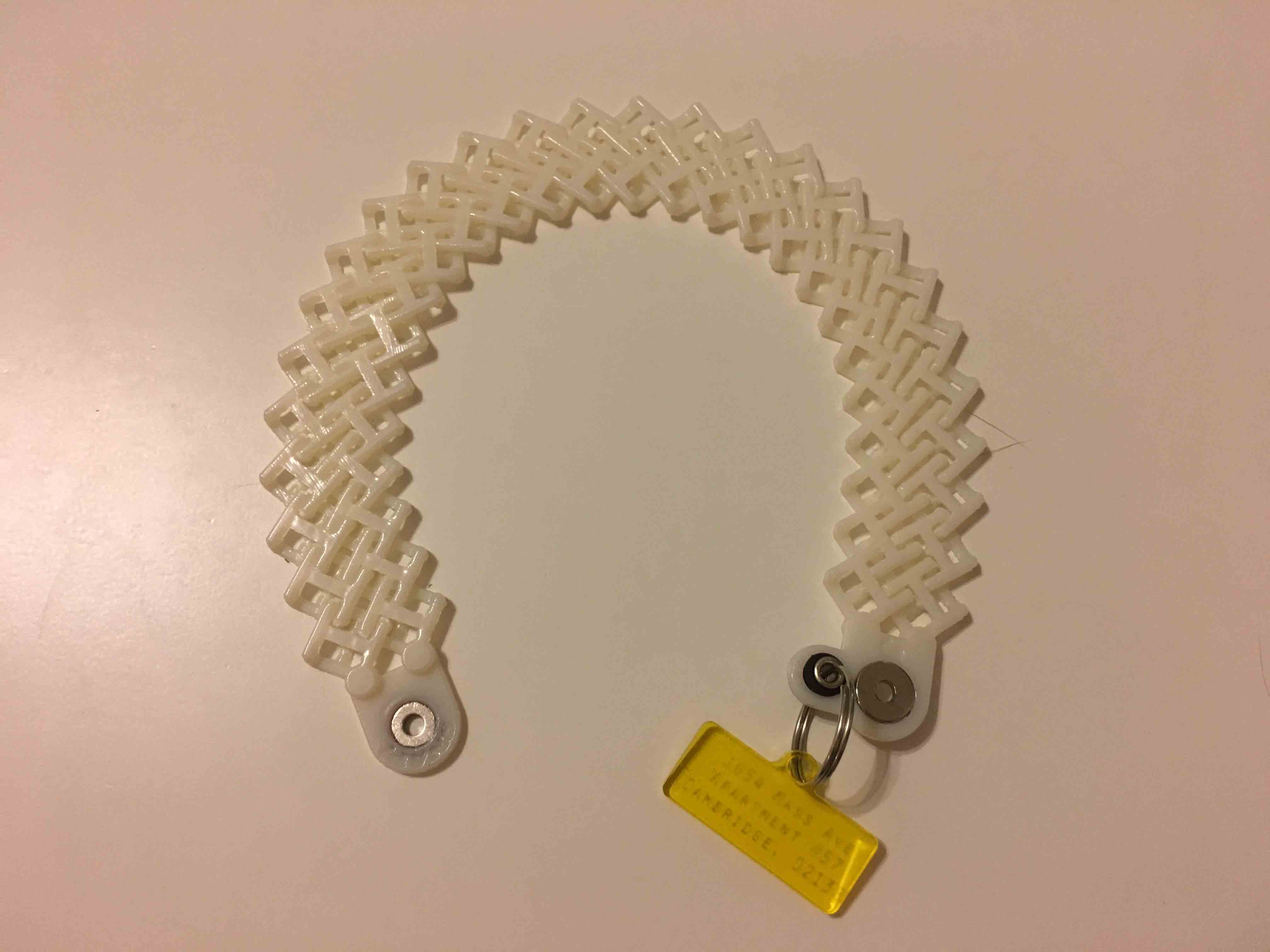
Lastly, I added a little rubber grommet to the hole that contains the keyring to ensure that the 3D print doesn’t break under stress from Jack’s name tag. You can probably tell I had fun this week - next time, I’d print this out of the black that the ABS printer had!
This week was definitely one of the harder ones for me, as it focused just as much on coding/software as it did on tangible prototyping. Nonetheless, by the end of it, I had a working in-circuit programmer that was able to communicate with a python script and user interface!
We were tasked with developing our skills in PCB design - either in KiCad or Eagle - and designing our own boards based on Neil’s original schematic. We were also tasked with adding an LED and resistor for later use (at the moment, they do not do anything… but are wired and ready for use with a pin on the ATTtiny44).
At first, I chose to work in KiCad, but I couldn’t get it to work the way I wanted to. The user interface was a bit backwards for me, so after a few hours of banging my head against the wall, I switched to Eagle.
After a long *LONG LONG* time of importing the fab library and choosing my components, wiring them, and placing them in ideal positions, I developed my schematic. As you can see, the first one was a bit problematic, as its leads were too close together.
At Rob’s suggestion, I increased my tolerance for neighboring leads and elements, and ultimately went with the trace on the left.
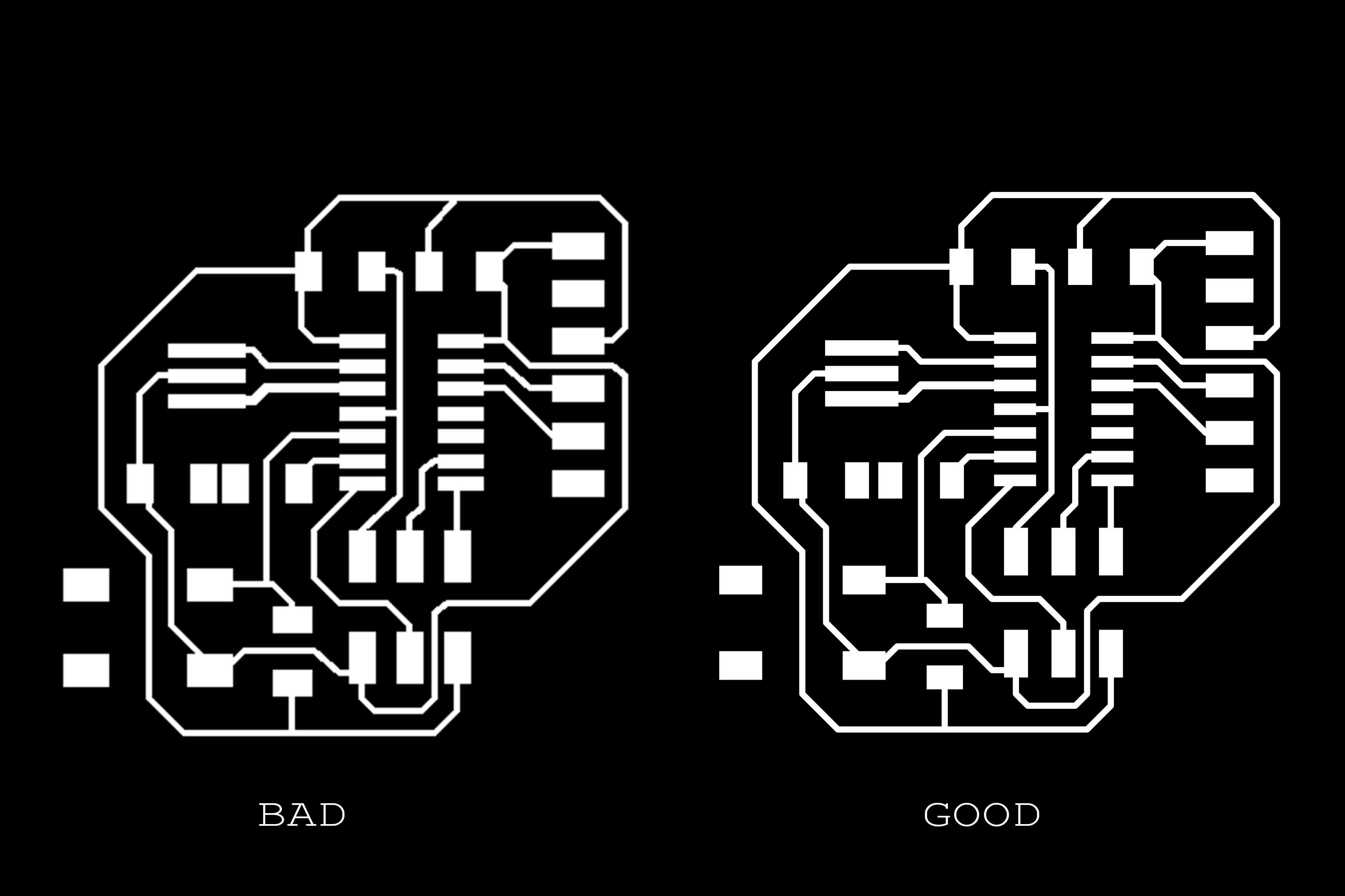
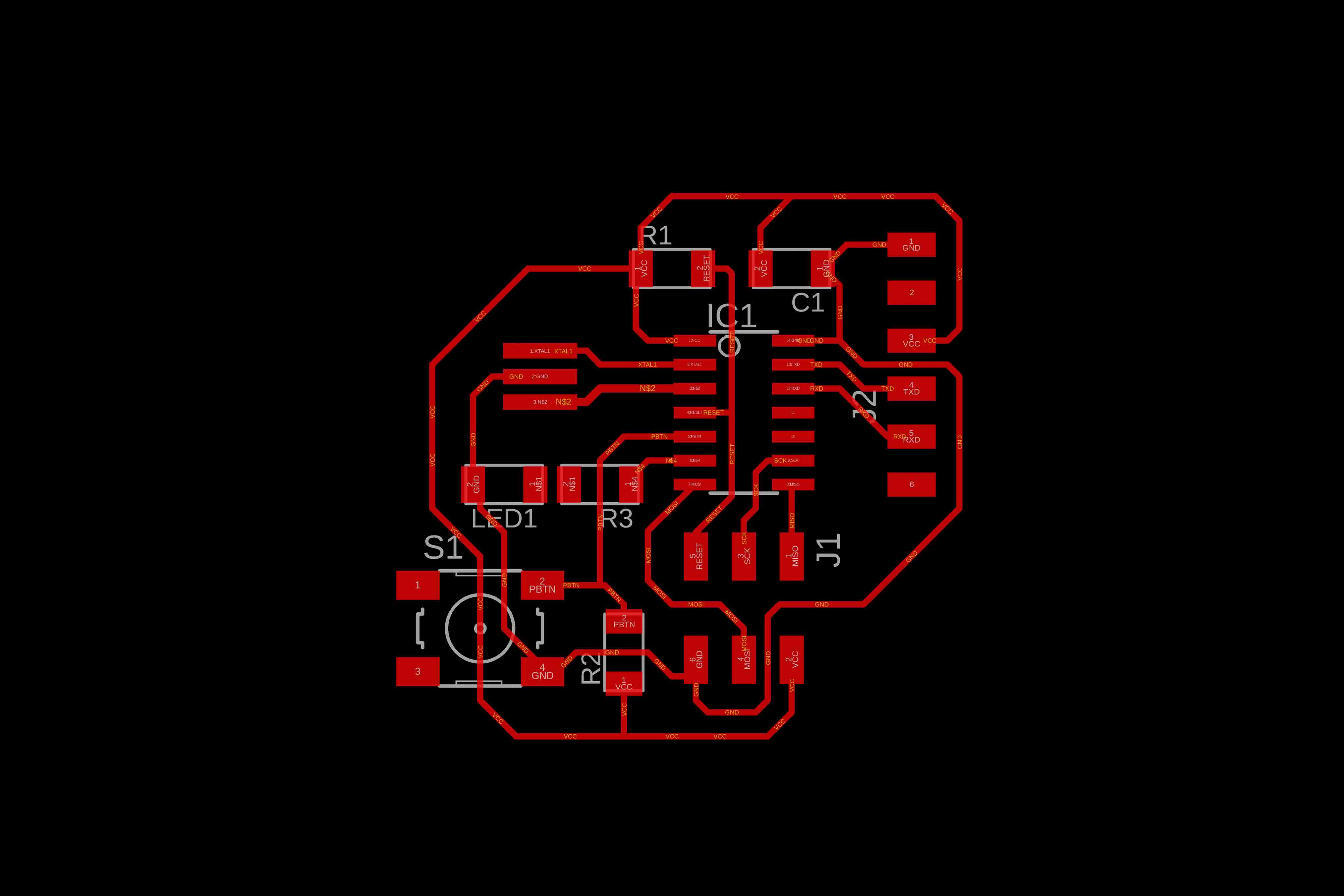
Here, you can see the final schematic. I chose to position the resistor and capacitor inherent to the original circuit as close to each other as possible, and similarly positioned the new LED and resistor within proximity to one another.
I should also mention that I chose to work with Eagle because of its wonderful layer management. By toggling layers on and off quickly, I was able to render and export various PNGs with different levels of overlayed information. Here, you can see the traces with the basal labels of components and directionality hinted at, as well.
As far as components go, I worked with all of the original pieces that were identified in Neil's schematic. For the additional LED and resistor, I went with a 500k resistor instead of the other two 10k resistors in the circuit, and red LED like in the previous week.
Just to be an idiot, I designed two border/cutouts for my board. Primarily, I knew I’d screw up the board while stuffing it, so I knew I needed to mill two boards just in case. I figured for the second board I’d shave off the sides to not have extra/excess/poking/stabbing material.
Then it was time to mill. There’s nothing particularly different to report here, as the process was similar to previous weeks when we first experimented with PCB production.
However, I should mention that I, along with several other students who own early generation MBP’s with Retina displays, had an issue with scaling. The first couple of sends from MODS were screwed up and the machine was milling at double the size that I needed.
I was able to fix this by doubling my resolution. Since I had exported at 1000 dpi from Eagle, I imported both the traces and final outline PNG’s at 2000 dpi. This fixed my issue.

After I stuffed the components in both of the boards, I tested my work. And, of COURSE, my first board didn’t work at all. Super fried and all the solders were sloppy. As such, I relied on my second, prettier board for a successful coding process.
While we were able to get the computer to communicate with my second board preliminarily, some faulty leads inhibited long-term communication. Specifically, Rob and I saw that I had an issue with my time-clock. On the oscilloscope, we couldn’t identify any expected behavior. As such, I went back to work and fixed up my stupid solders.
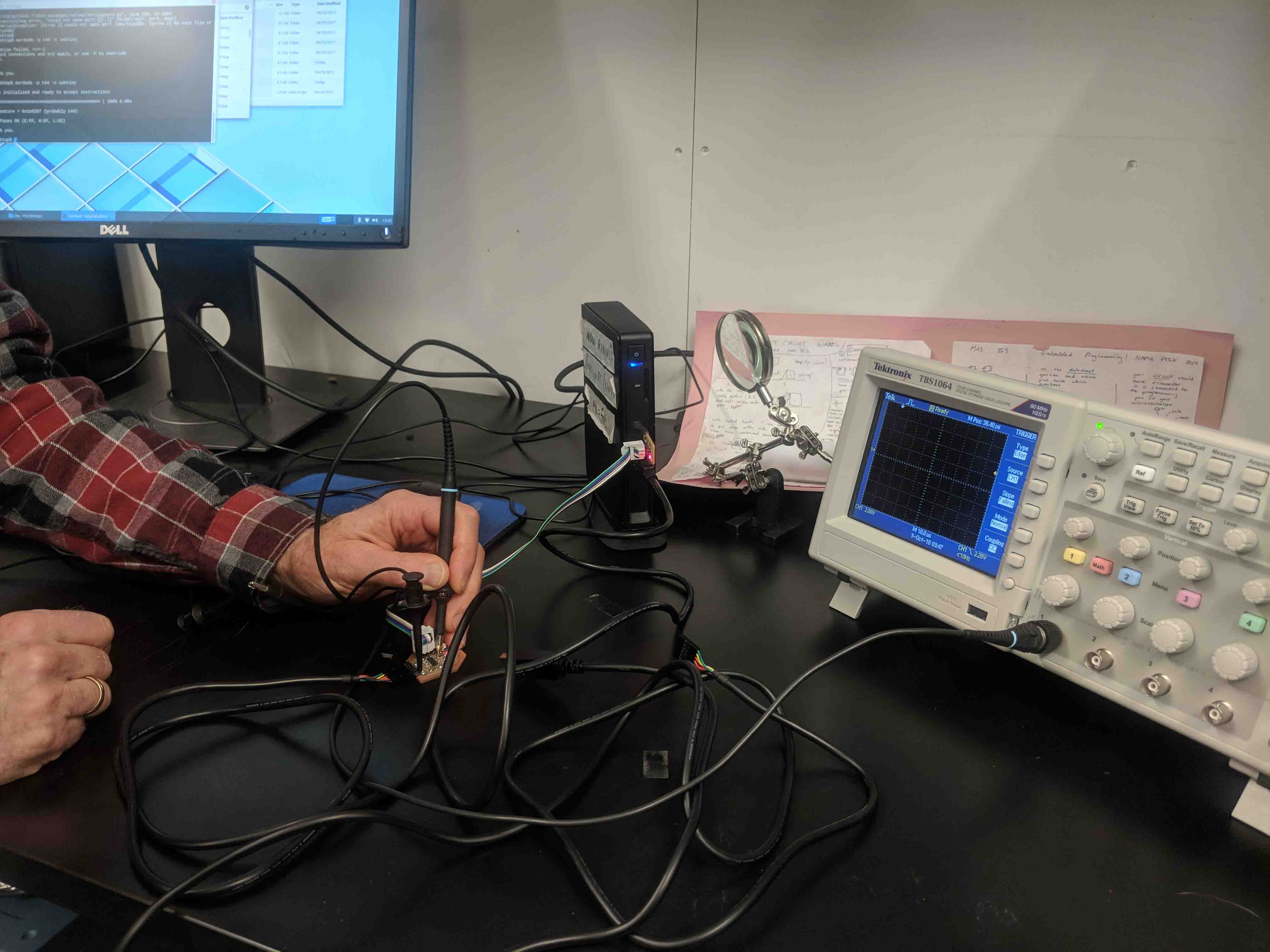
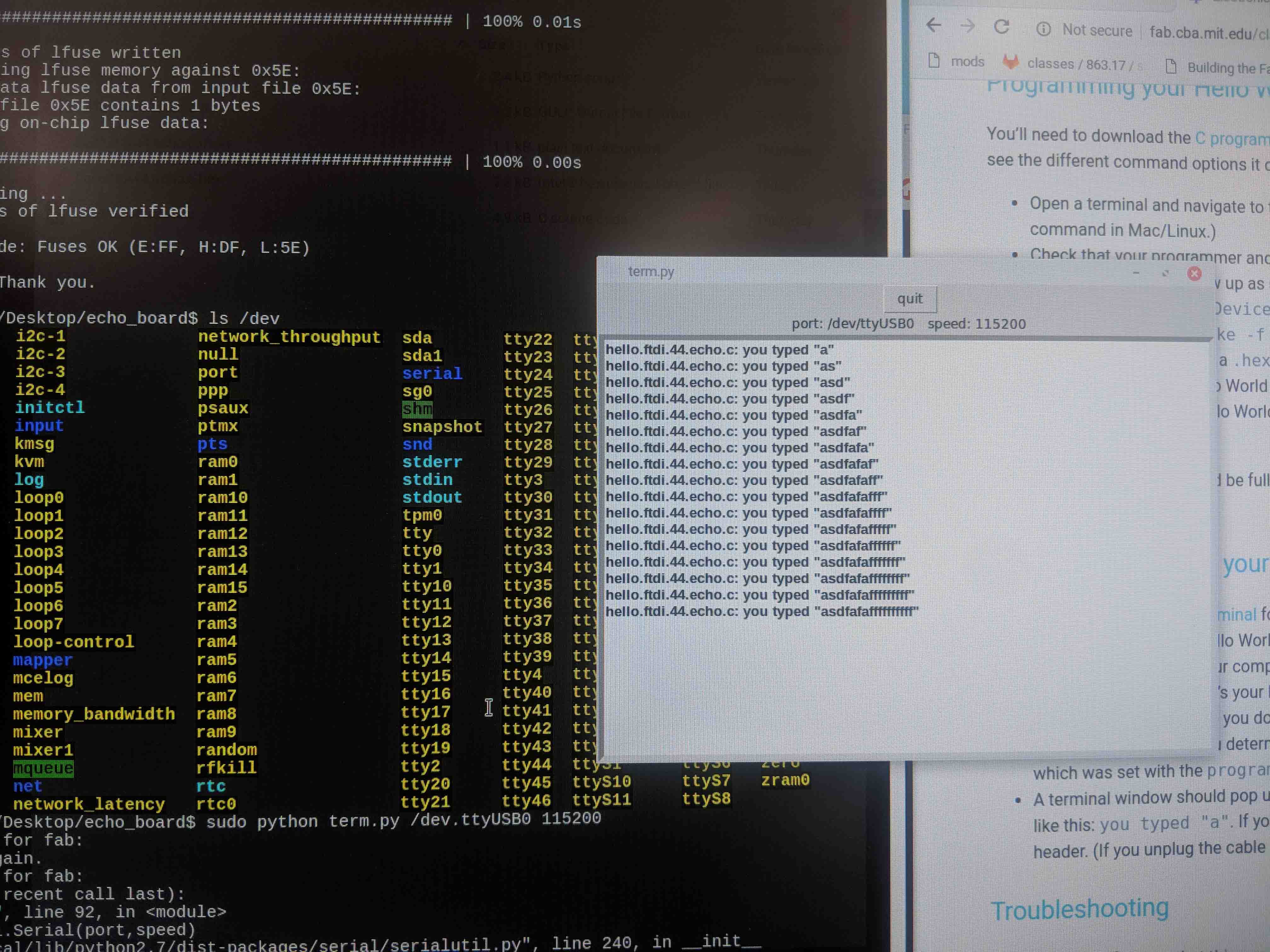
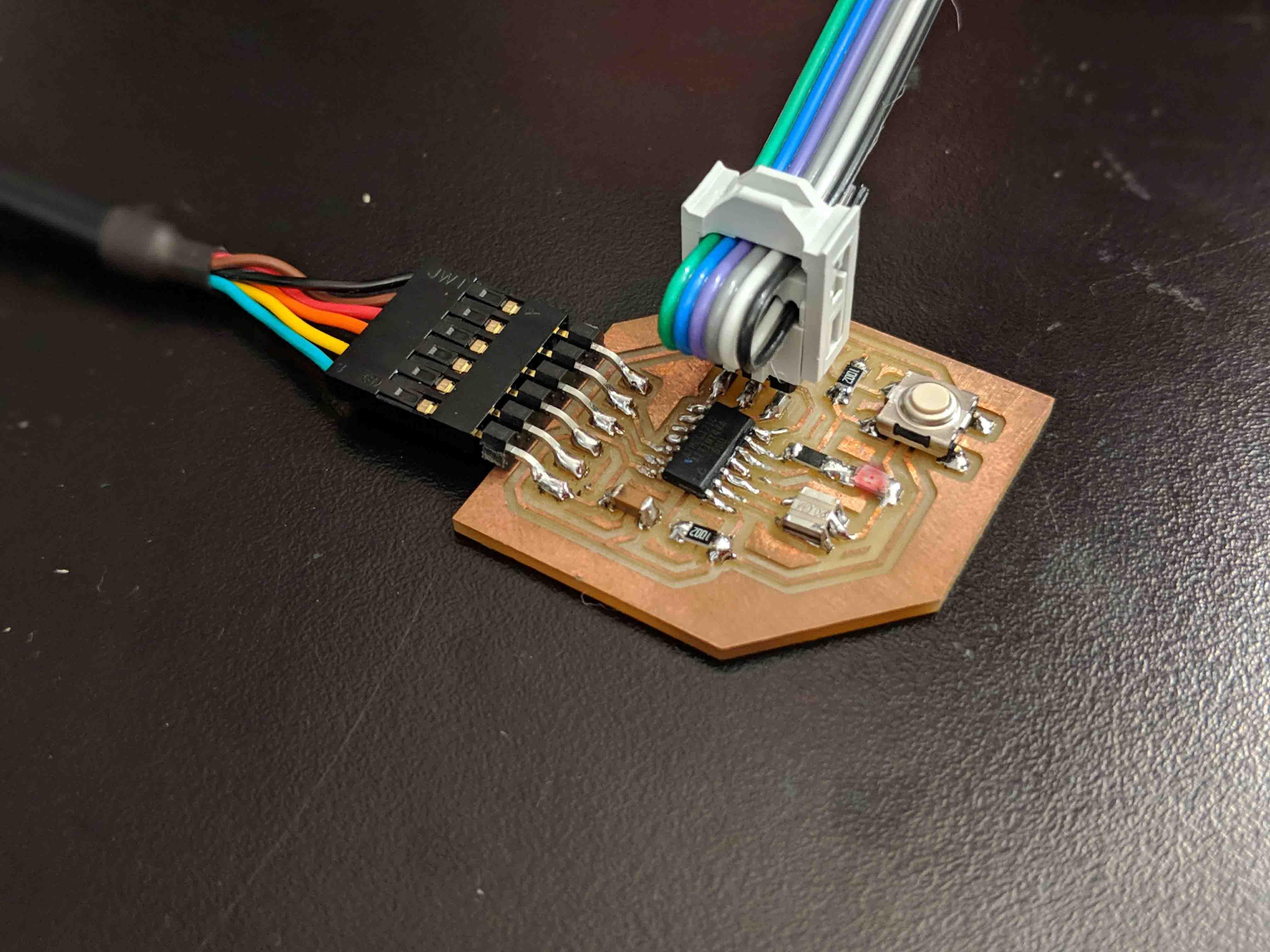
As far as flashing, programming, resetting fuses, and eventual communication goes, this process went pretty smoothly after Rob and I had successfully fixed that time-clock. Here, you can see the board communicating back to me as I randomly typed in characters into my keyboard.
I'm not going to lie - this was an extremely frustrating week, filled with finnicky software learning curves and random issues based on hardware/OS. Such is life, I suppose. I'm just glad the board works!
This week, we focused on CNC milling, which is already something that I am extremely familiar with thanks to Carnegie Mellon and my experience with their digital fabrication lab (dFAB).
I decided to stick to simple 2D and 2.5D cutting, but wanted to make something that I needed desperately in my apartment to continue the DIY aesthetic that I’ve been pursuing for this course.
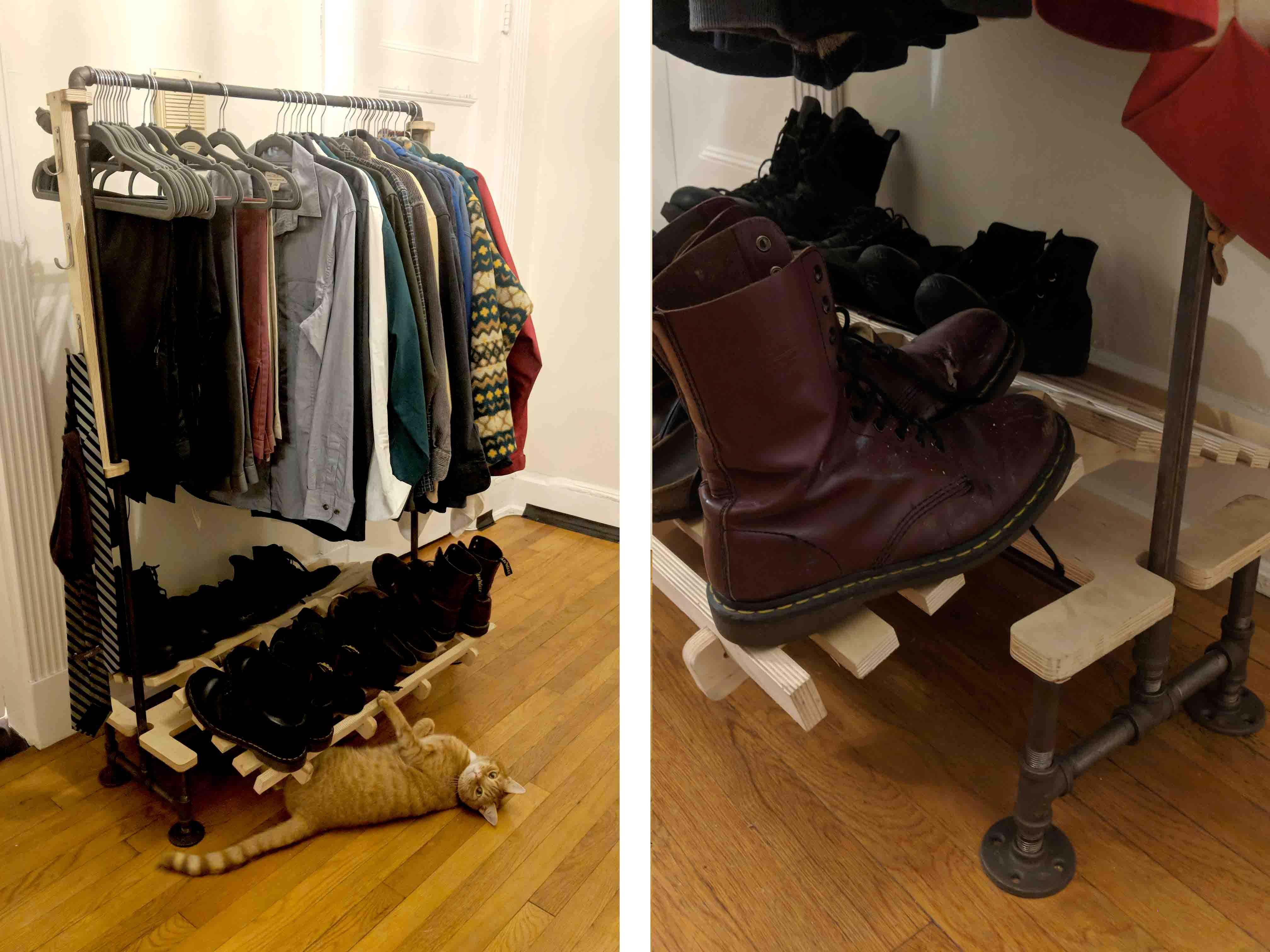
Long story short - in my recent move to Boston from Pittsburgh, my friend, who was driving a U-HAUL filled with all of my belongings, had a horrible wreck somewhere in Pennsyl-tucky. Needless to say, the majority of our stuff was destroyed, including a rolling closet I had purchased. For the last few weeks, I’ve been stacking my clothes in cardboard boxes, so I decided to create my own out of piping I found at Home Depot and a CNC milled shoe rack! Thanks to some baltic birch that was lying around the robot room at the GSD, I was able to get to this as a final result!
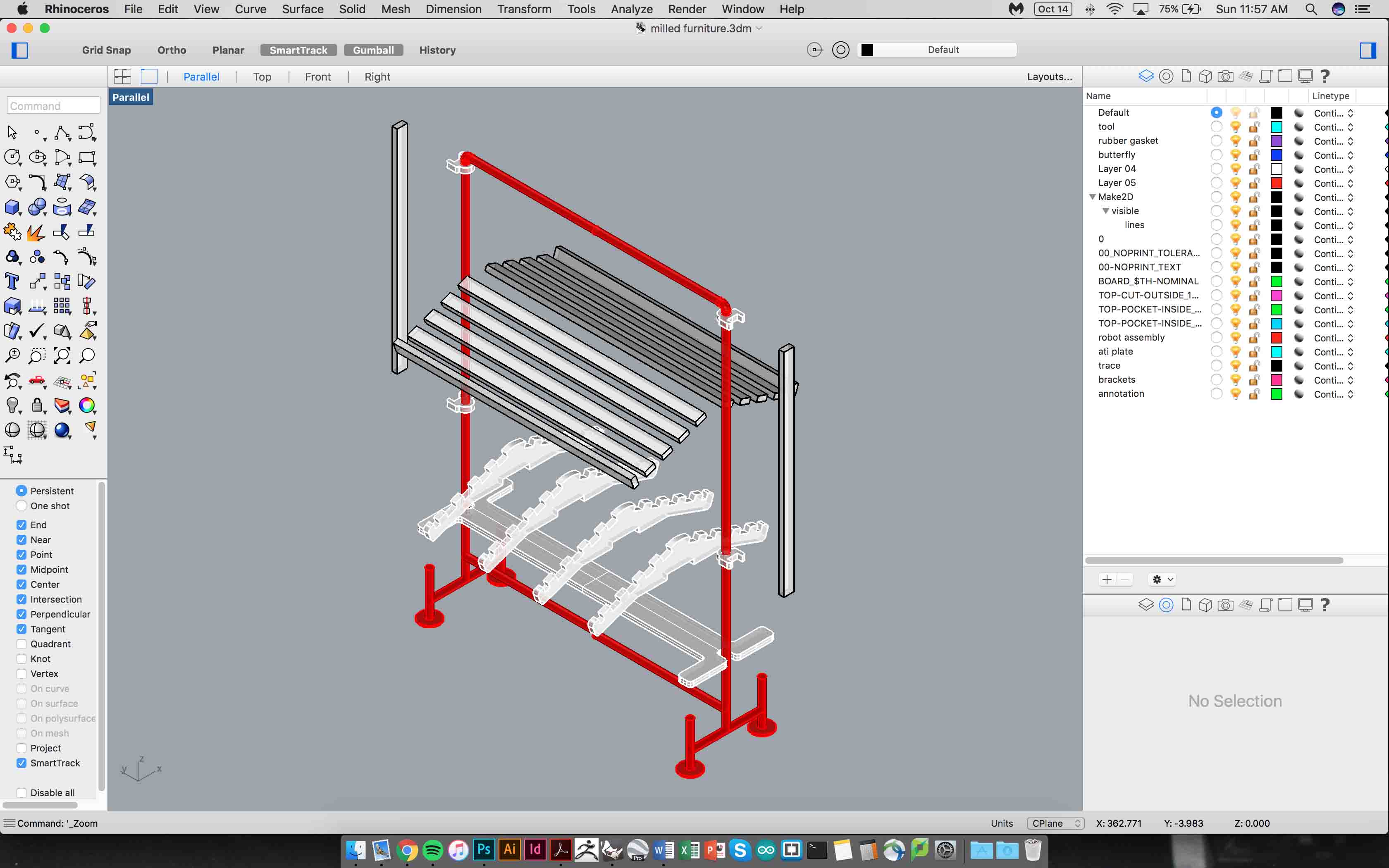
I began by sourcing the pipe, assembling all the parts, and taking precise measurements of the physical piping network before modeling in Rhino. I wanted the shoe rack to offer storage on both sides of the rack, so I designed rafters to slot to both sides.
I also incorporated side elements from which I would later hang hooks and other accessories to hang my hats, scarfs, ties, and tote bags. These would slot into these eye-hook pieces I designed, and would be screwed together.
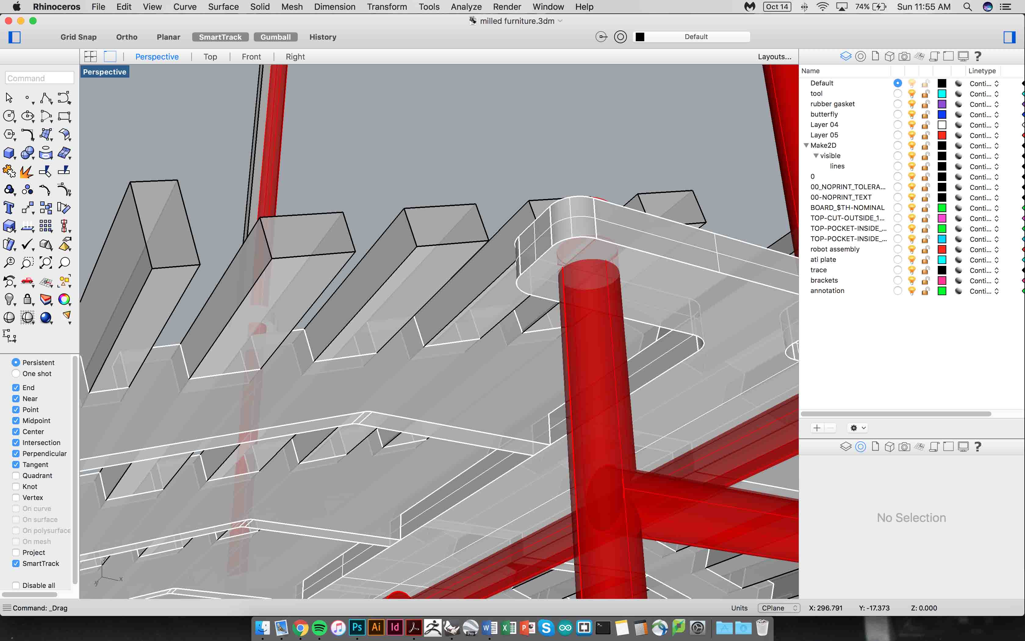
As far as the base went, I was relying on a tight fit and gravity to ensure that the whole rack rested on top of the pipe stands. I achieved this by pocketing out a small cylinder on each corner of the rack, but I didn’t pocket all the way through the thickness of the baltic birch. This allowed the rack to rest easily on the pipe.
I admittedly guesstimated the snug fit as far as the cylinder diameter goes. I knew that it wouldn’t hurt to go too large, as the worst thing that could happen would be a little bit of jiggling. Everything worked out in the end, it seems.
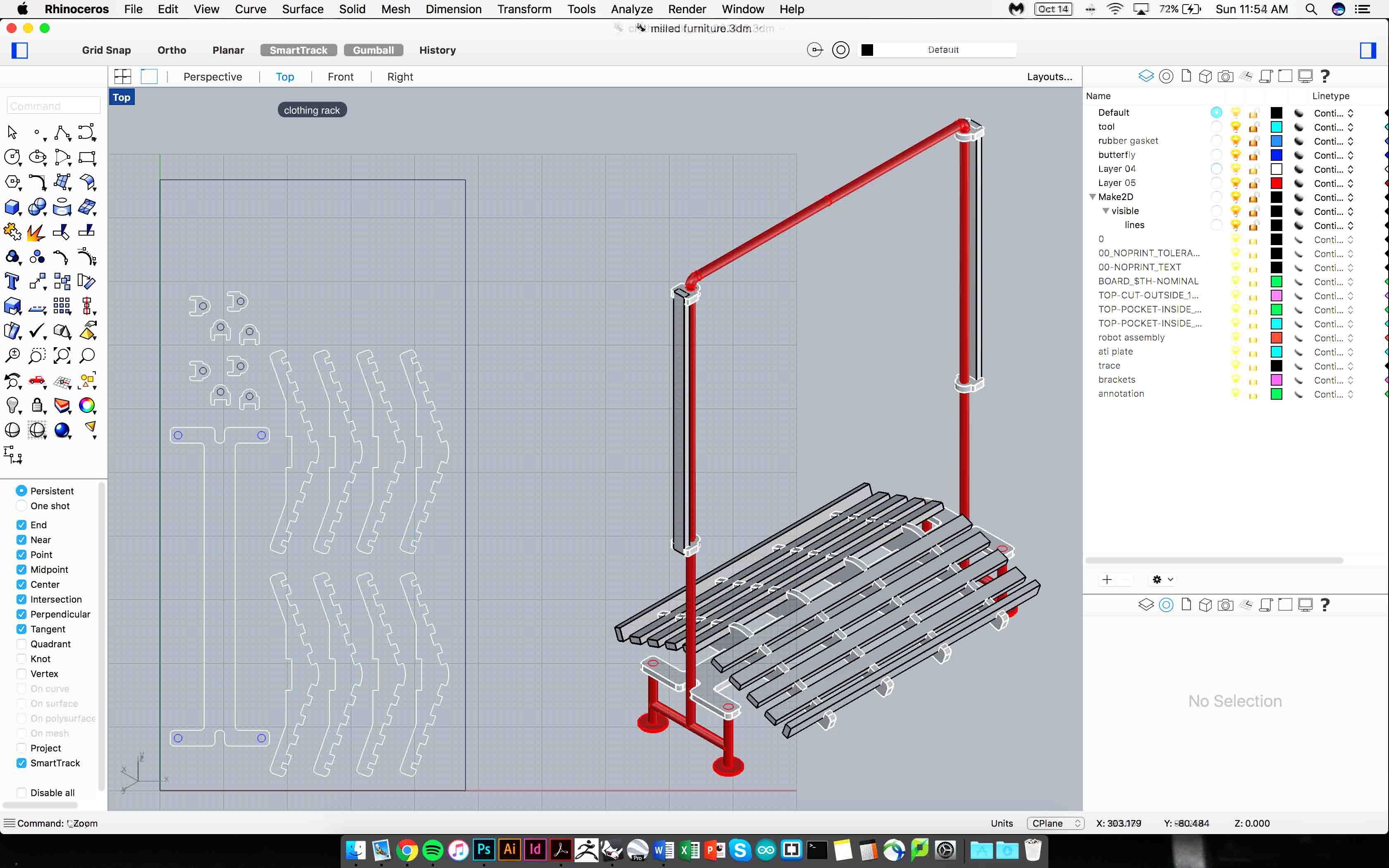
Then it was time to make a cut sheet and see how I could place my pieces around the stock that I had to work with. Though you see a full sheet of 4’ x 8’ modeled here, the baltic birch that I had to work with was noticeably smaller.
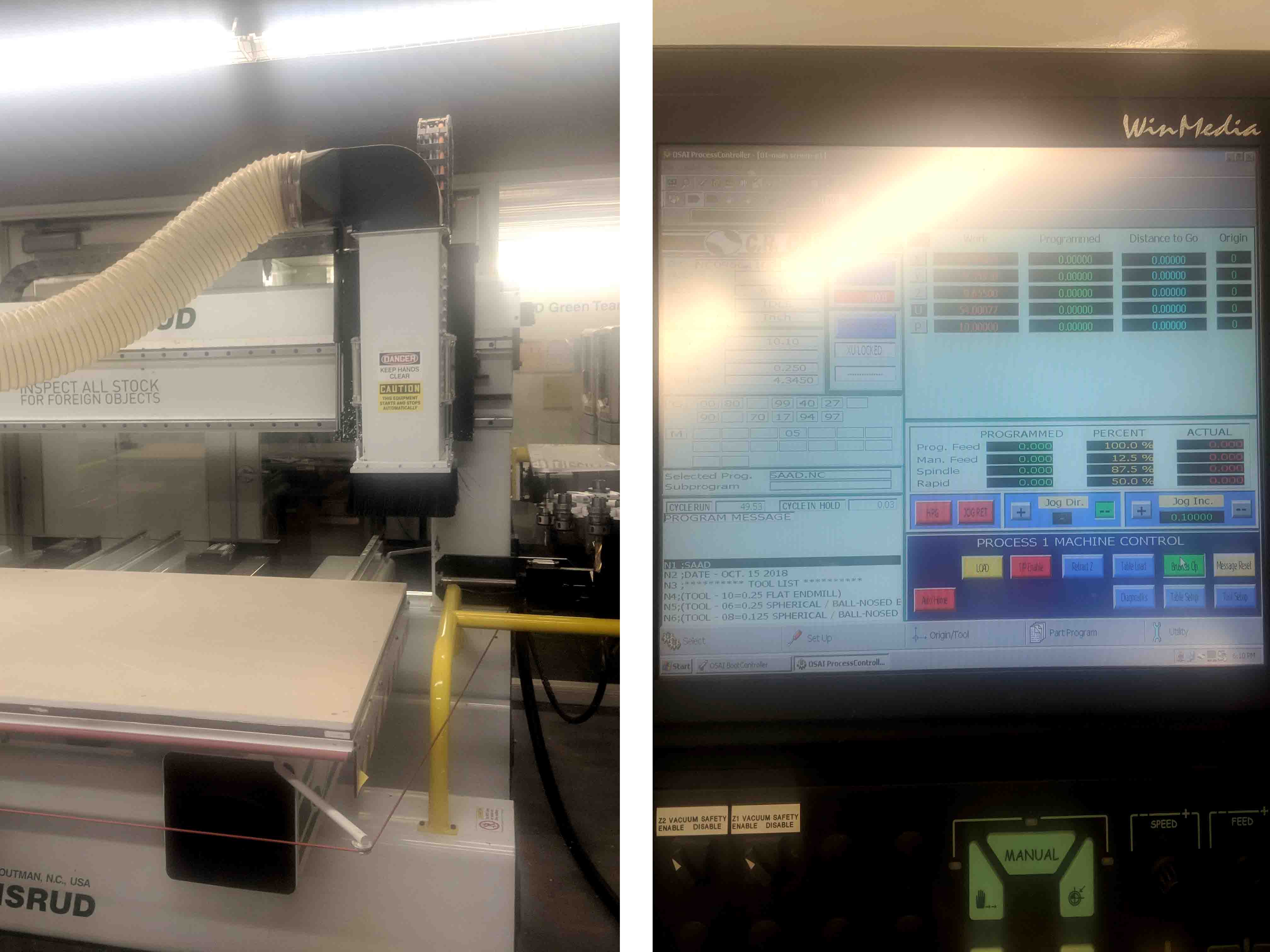
The milling process went smoothly and there isn’t anything notable that I can think of to mention, other than the fact that I absolutely adore the Osrund and I always wished that Carnegie Mellon had one.
Also, I was excited to take advantage of the GSD’s compression bits, which incorporate both downwards and upwards flutes. This allowed me to plunge into my plywood without having to incorporate any step-down into my G-code.
The effect is actually a bit amusing to watch - the CNC literally eats into the material in one pass, and leaves behind a resultant that has no burrs, broken edges, or sloppiness. I didn’t have to use any bridges for the base, but decided to add little table to each of the smaller pieces to make sure they didn’t fly off the vacuum bed.
After milling, I didn’t have to sand anything - just went to woodshed to make the little slats that actually hold the shoes.
I also installed the hooks and miscellaneous hardware/screws that I had planned for the build.
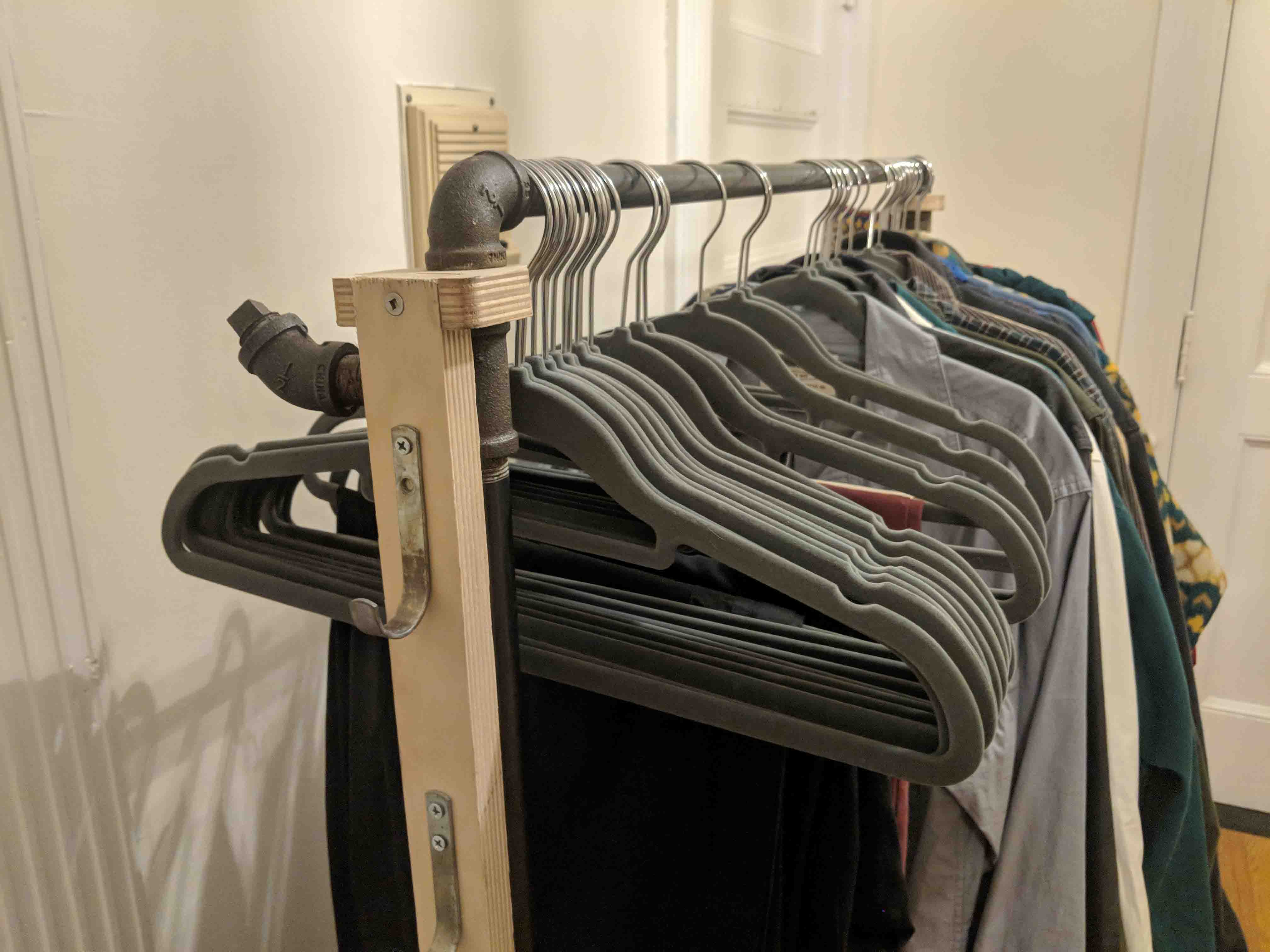
I’m actually pretty happy with the result. The base is surprisingly sturdy and solid, and it even serves as a fun place for Jack to play and sleep.

Next time around, I’d probably have incorporated a stain or varnish or sort to really bring out the grain of the plywood. But for now, this is where we’re at.
This week, we were tasked with programming code onto the boards that we had previously designed and milled a few weeks ago.
This was a super daunting task for me, so I decided to take it slow, be modest, and use the Arduino IDE instead of some of that scary Terminal stuff. I’m also hoping to use Arduino – based hardware in school… especially for my final project for this class.
All I really had to do to get my board to communicate with IDE was to install the support files for ATtiny. A lot of online help and forum searching helped with this process, though it definitely seems ubiquitously understood at this point. Once I was able to see the ATtiny in the serial monitor, I knew I was set.
Since I’ve been accumulating a collection of pieces from previous weeks (which I happily call “the graveyard”), I was able to use my programmer from a few weeks ago to communicate with IDE and the board that I was trying to program.
I used my programmer from week 2 to program my board in the Arduino IDE. It required quite some troubleshooting (both to get the code onto the board and correcting the clock).
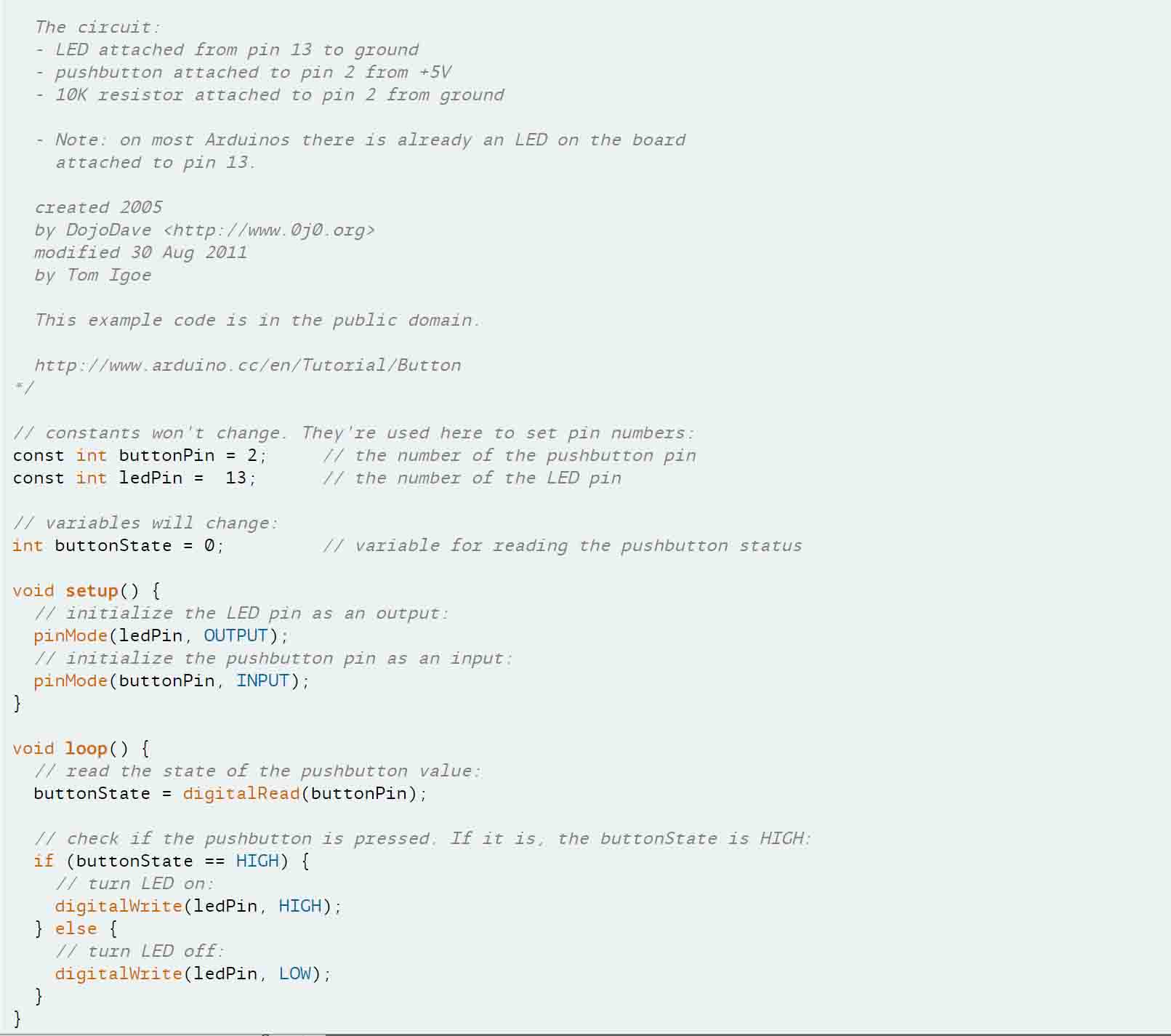
This process went surprisingly well, and I was able to upload both the “blink” code and “button” code quite easily. The codes I used for them are provided below...
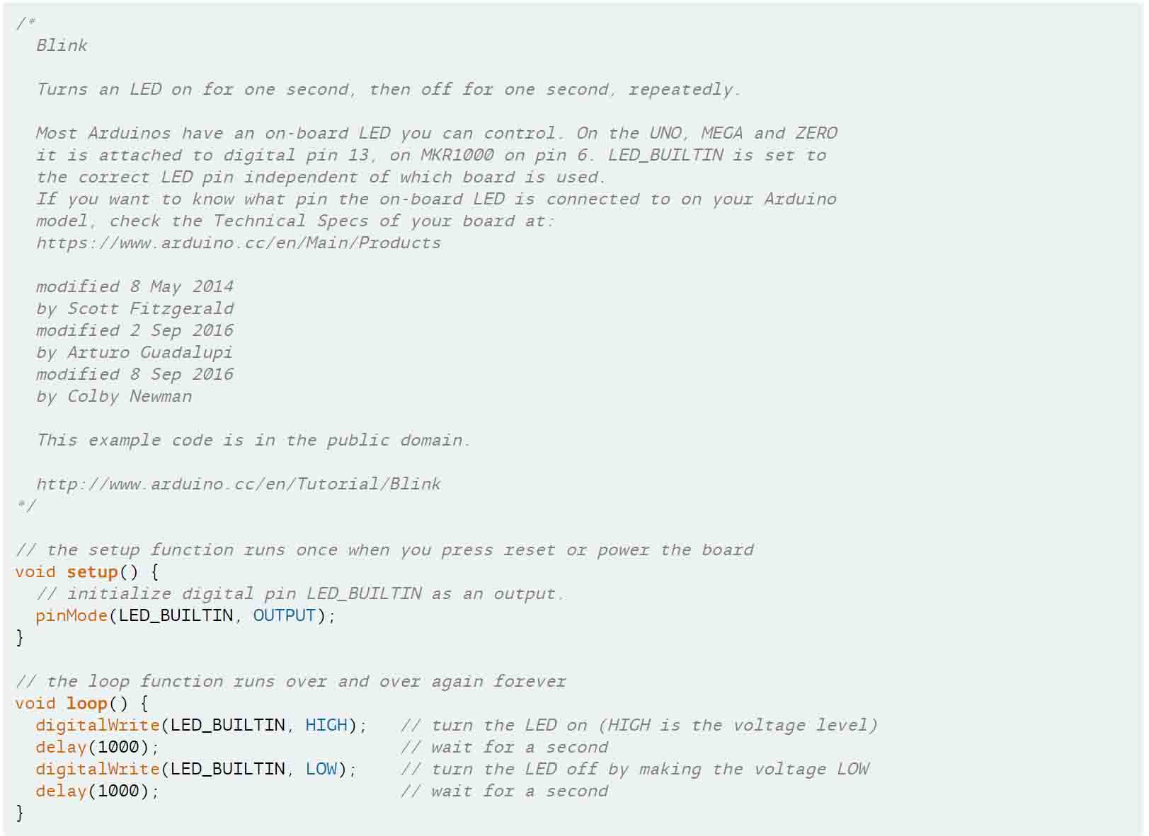
...and here as well.
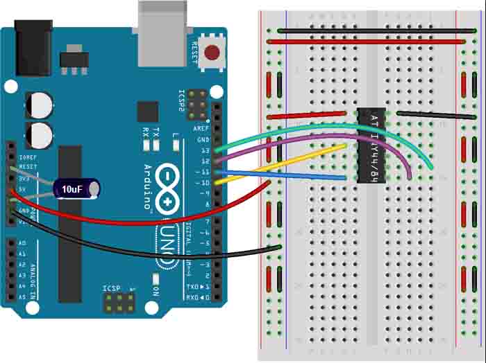
I then tried to be a bit less modest and use the actual Arduino as a programmer, as opposed to my homemade programmer, but I never seemed to get it right. I’m pretty sure that all my pins were connected correctly, but I never seemed to get past error codes. I’m thinking it’s a driver or library of some sort. It could also be possible that I’m supposed to use a native, non-knock off Arduino. Mine is called Elegoo or something silly like that. I got it from Amazon for cheap, I remember.
Nonetheless, I tried to follow this schematic, which didn’t work out for me.
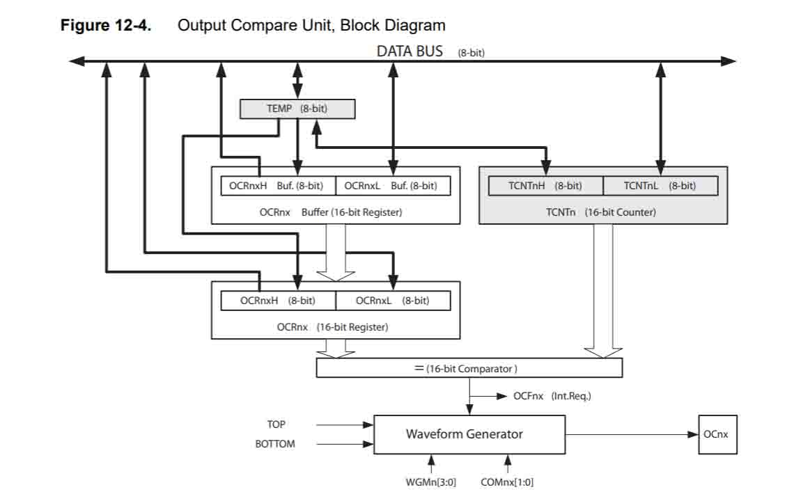
Lastly, to feel good about myself (and I guess fulfill the requirements for the week), I skimmed the data sheet for our ATtiny. Not much to report here, other than the fact that I’m continually amazed at the seemingly infinite scale of universes that exist in this tiny thing.
For someone who has tremors, I can’t imagine actually building these damn things.
This week we started to look into molding, casting, and their associated techniques and methods. I’ve had some experience with water-based plaster before, but I had never worked from a positive to a negative and then back to a positive. As such, I was excited to see where this week would get my skillset to.
I knew I wanted to start denting into the components for my final project, so I decided to design something that I could use. Because I need several control knobs, I spent around 45 minutes designing a quick knob in Rhino, and exported it as an STL.
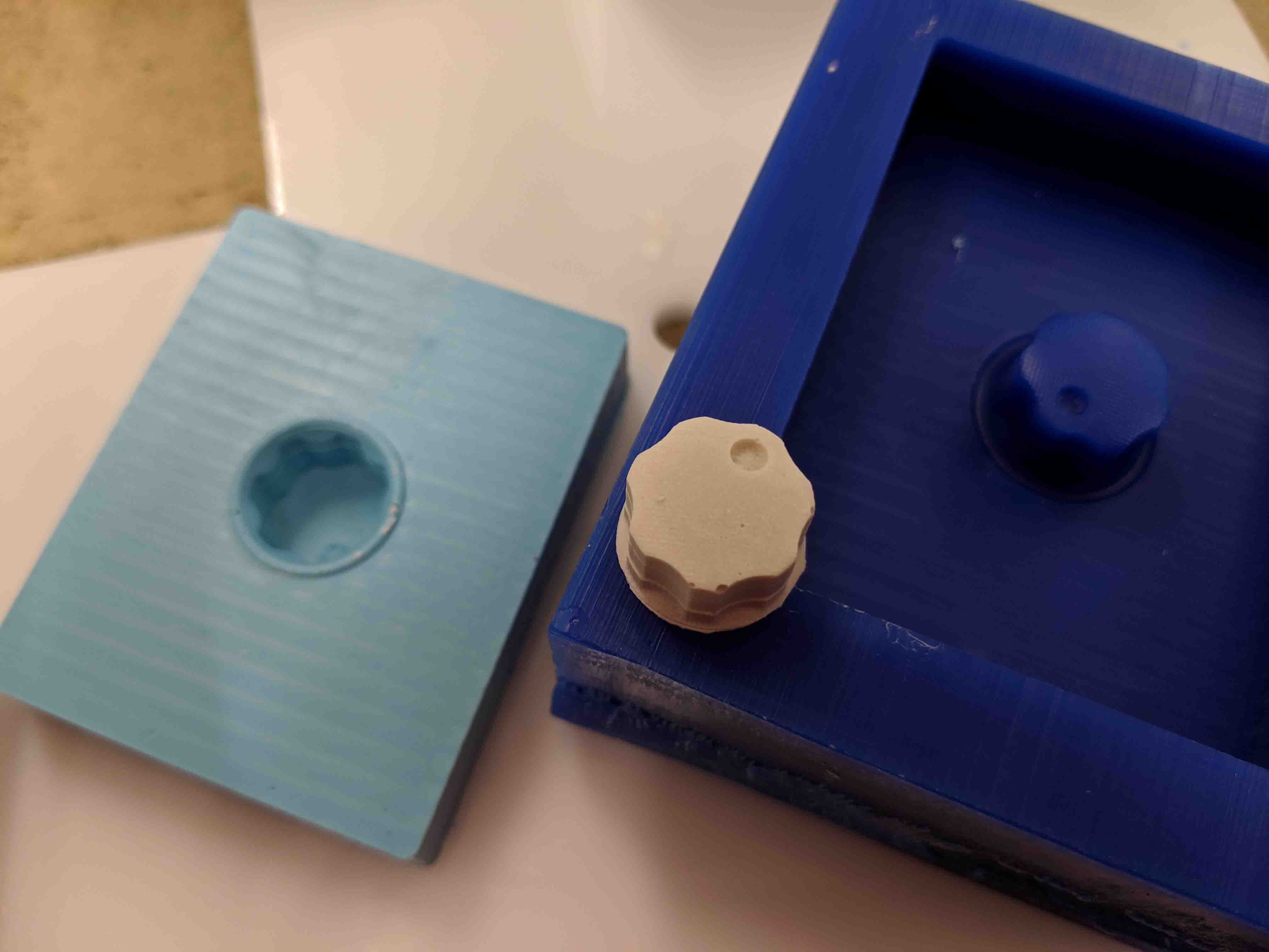
Then, I went to the ShopBot to mill. Thanks to Rob and Jackson, this process went pretty swimmingly - though I’ll admit that it requires some backwards thinking to figure out how to actually make real what you want to create. I ended up using an 1/8” end mill for the horizontal roughing, and a 1/16” end mill for the parallel finishing. I performed this second pass twice, one in each coordinate direction, so as to minimize ledges and excess material lines.
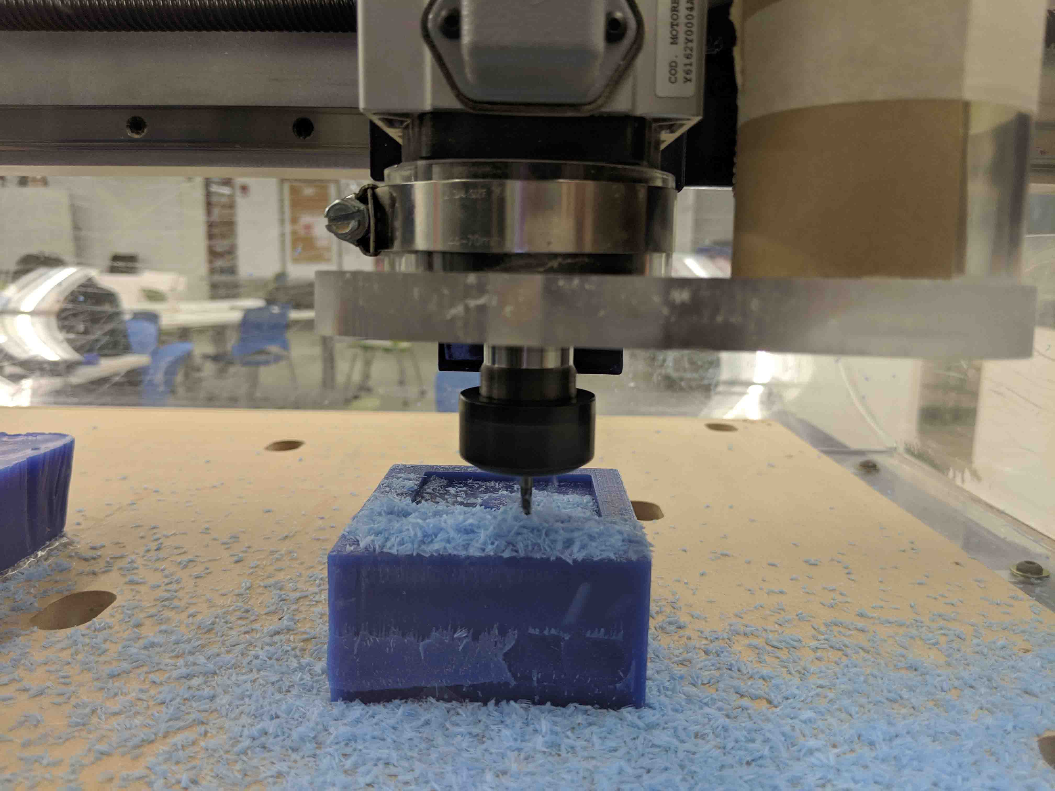
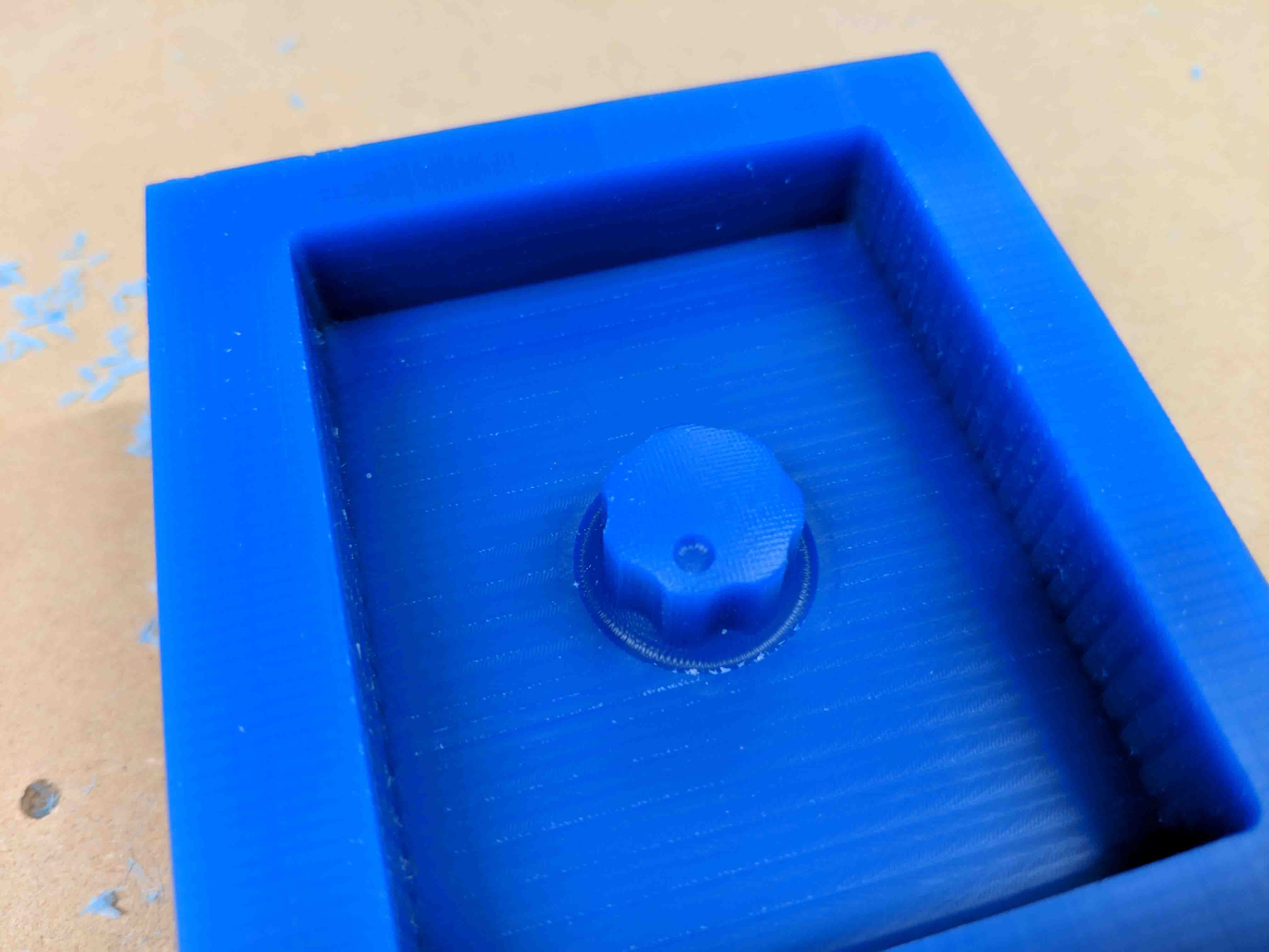
The end result actually came out really nice! I think that next time I would have accommodated for a deeper cut to ensure that the silicon cast I make doesn’t have too thin of a wall. The top of the knob, pictured here, is pretty close to the material top - at around an 1/8” clearance.
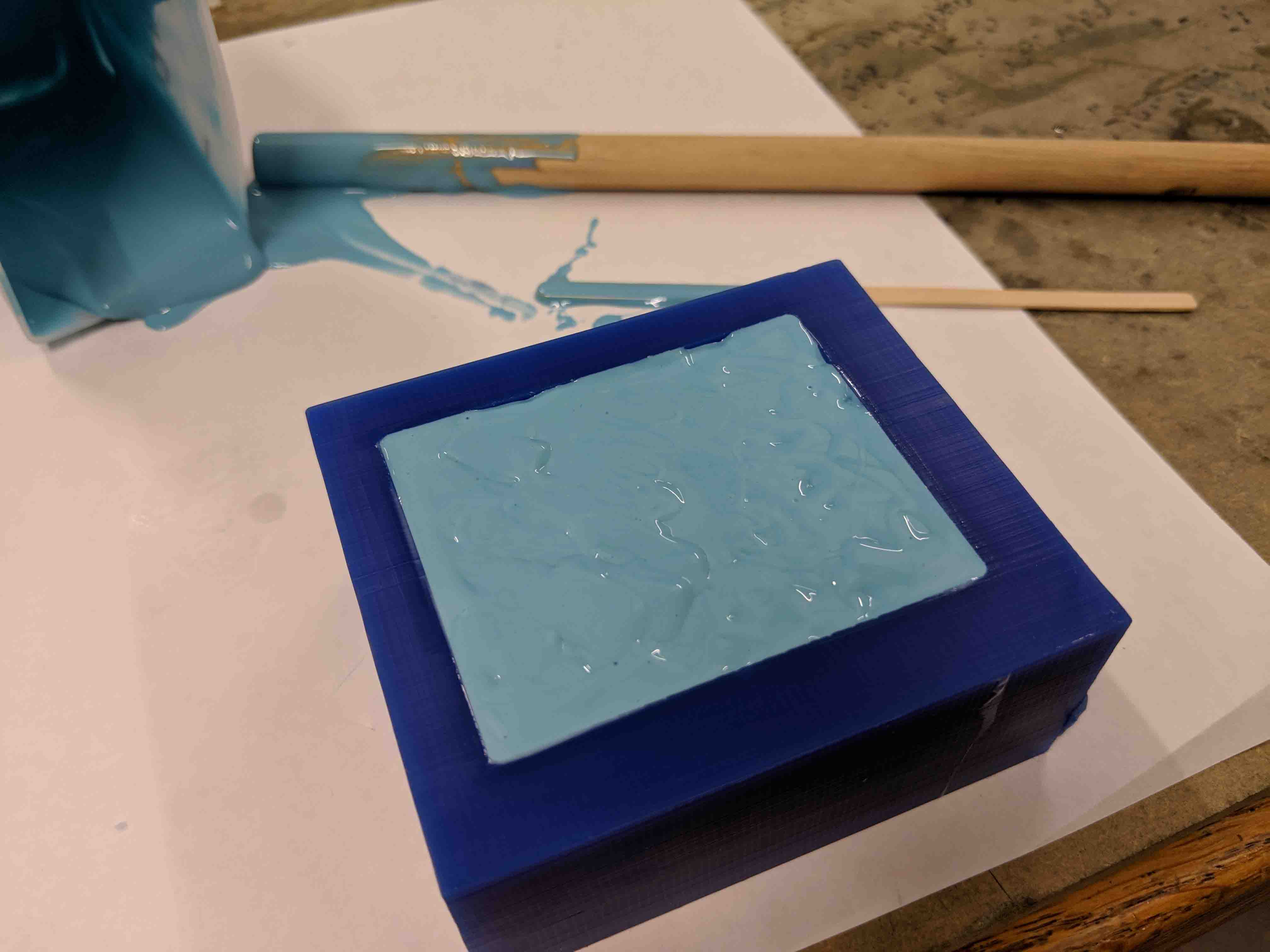
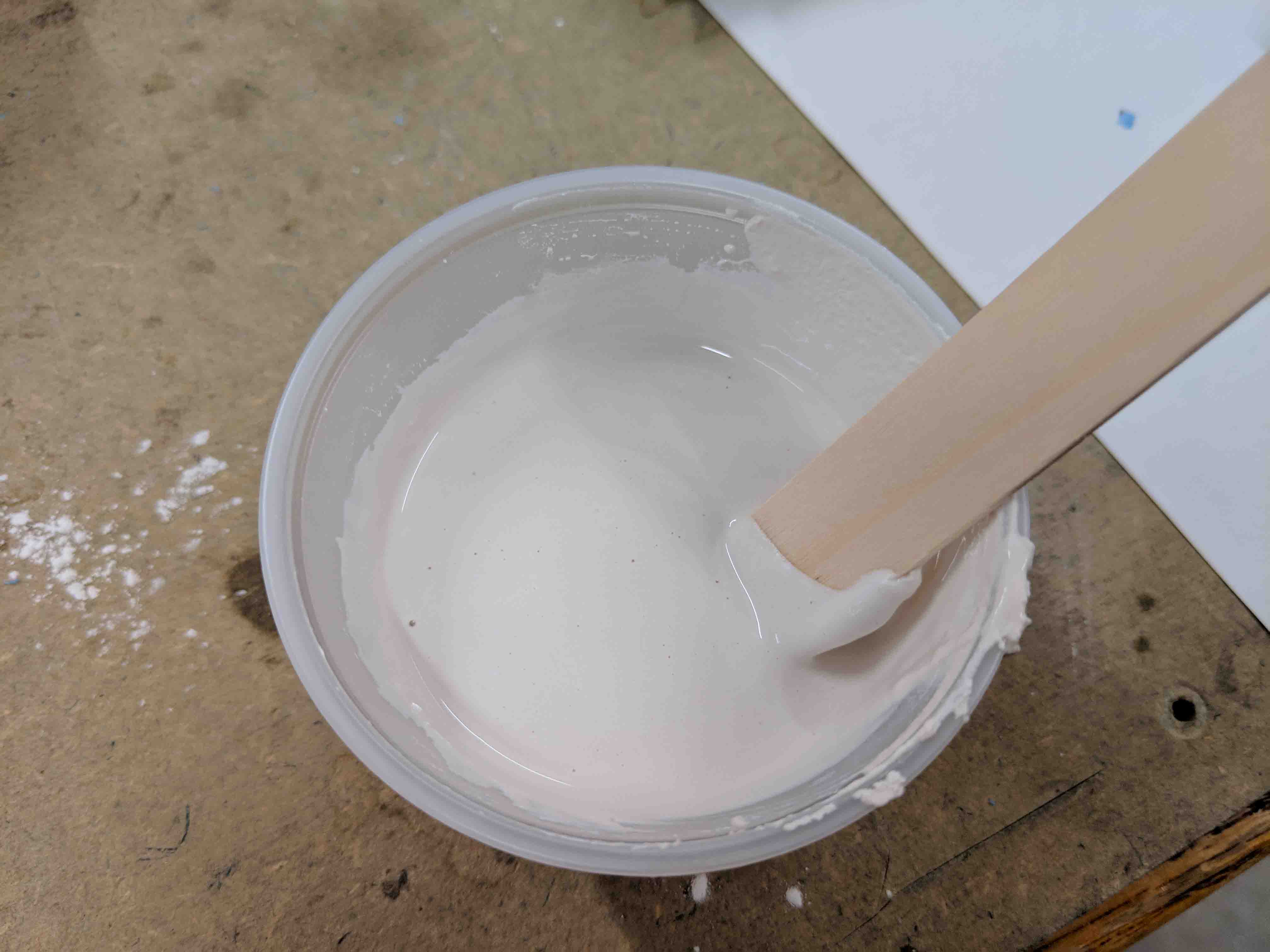
Then, I mixed the OOMOO according to the specifications on the data sheet (read the data sheet! Read the data sheet!!). This went pretty fine, and was actually quite therapeutic, forcing me to slow down to make sure that I didn’t have any bubbles. A mixture between slow stirs and soft taps on the table best minimized air bubbles for me.
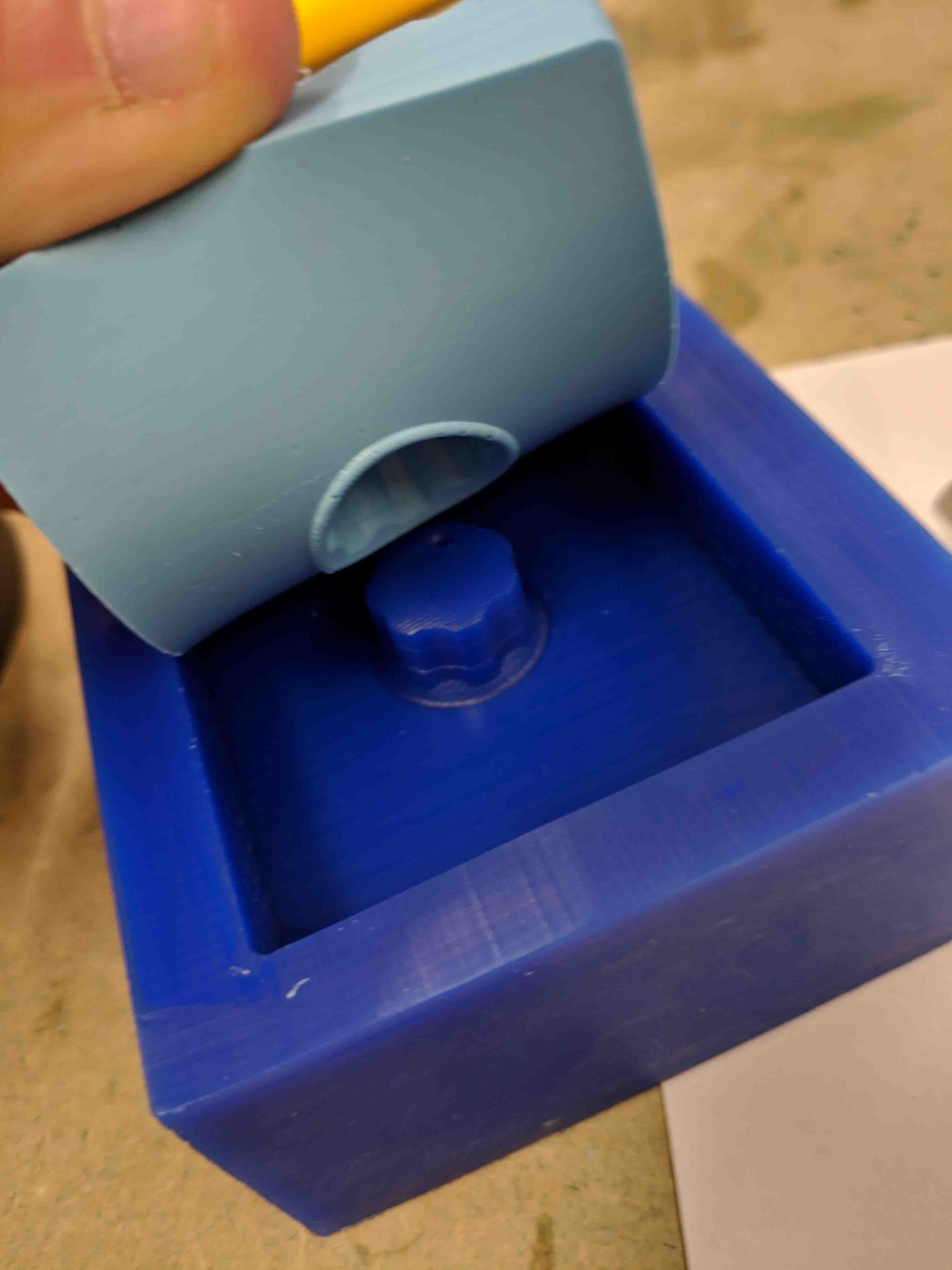
Peel-away went pretty smoothly, too! Just a few bubbles/holes on the inside of the part, but to be honest, I thought I was going to do worse of a job.
Then, it was time to mix the material I was casting into the mold for the final positive object/knobbie. I chose hydrostone, because I wanted a simple, albeit strong cast.
Here’s where I made a super embarrassing mistake - while I nailed the ratios of materials for the mix, I just made way, way too much.
This should be pretty obvious from the mixing image, but I just didn’t know what to do with the excess - so I just cast it into a mold I found laying around and made a weird geometric cow patty thing.
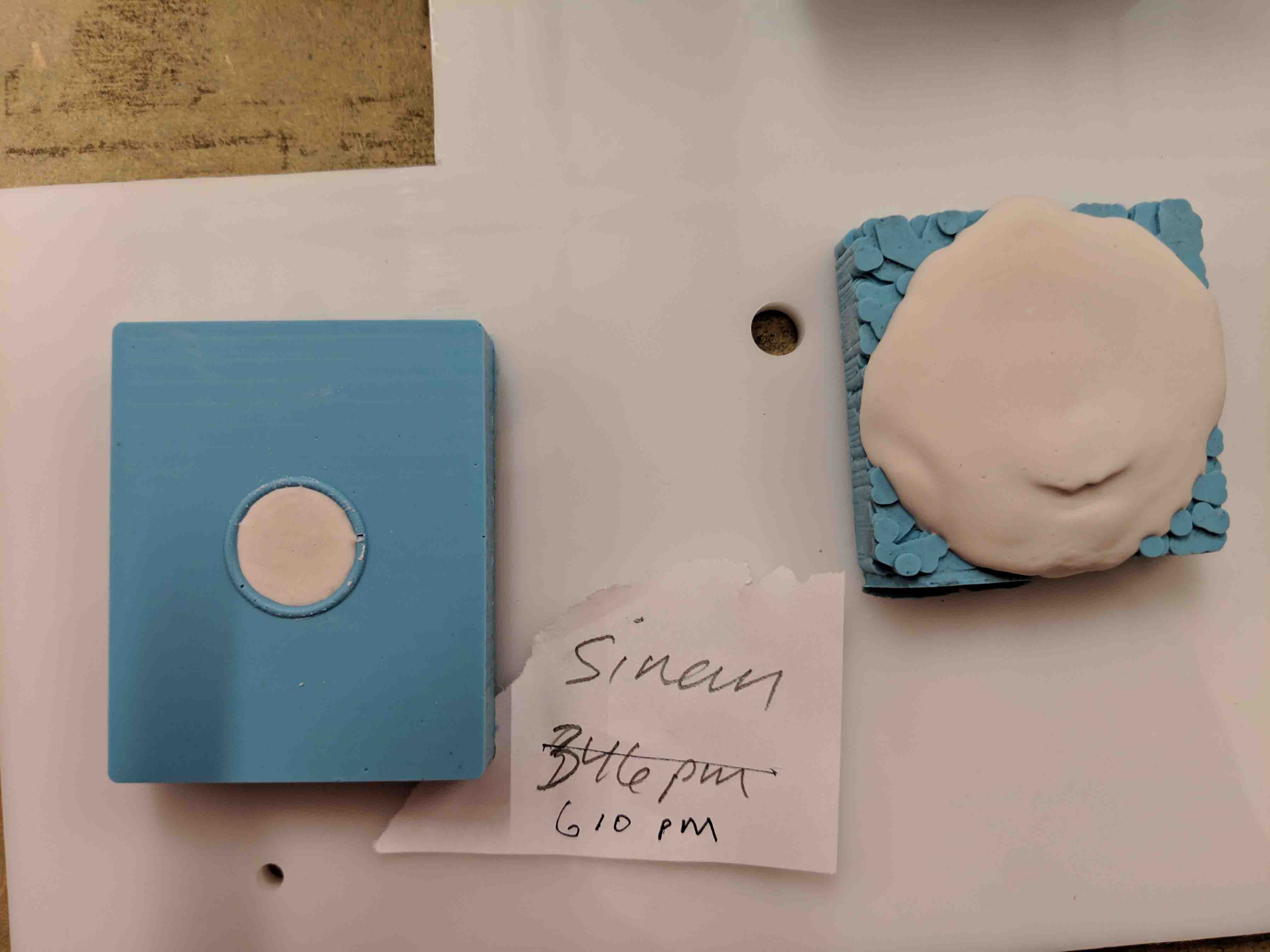
Most importantly, the actual part that I was trying to make the whole time came out! You can see some slight imperfections and artifacts, which are likely due to the bubbles that I previously mentioned, but overall, I’m super pleased with this.
Next time, I think I’d develop a two-part mold rather than an open faced mold so as to design the back of the knob and accommodate it for a thread of some sort.
I’m an idiot.
Though I thought I wouldn’t do it again after high school, I made the mistake of completing the wrong assignment for this week… looking at the “output devices” assignment instead of the “input devices” assignment. Pretty sure Neil will call me out on missing the memo so my apologies in advance. Nonetheless, this week’s submission focuses on the output devices assignment… I guess I’ll do the input device next week.
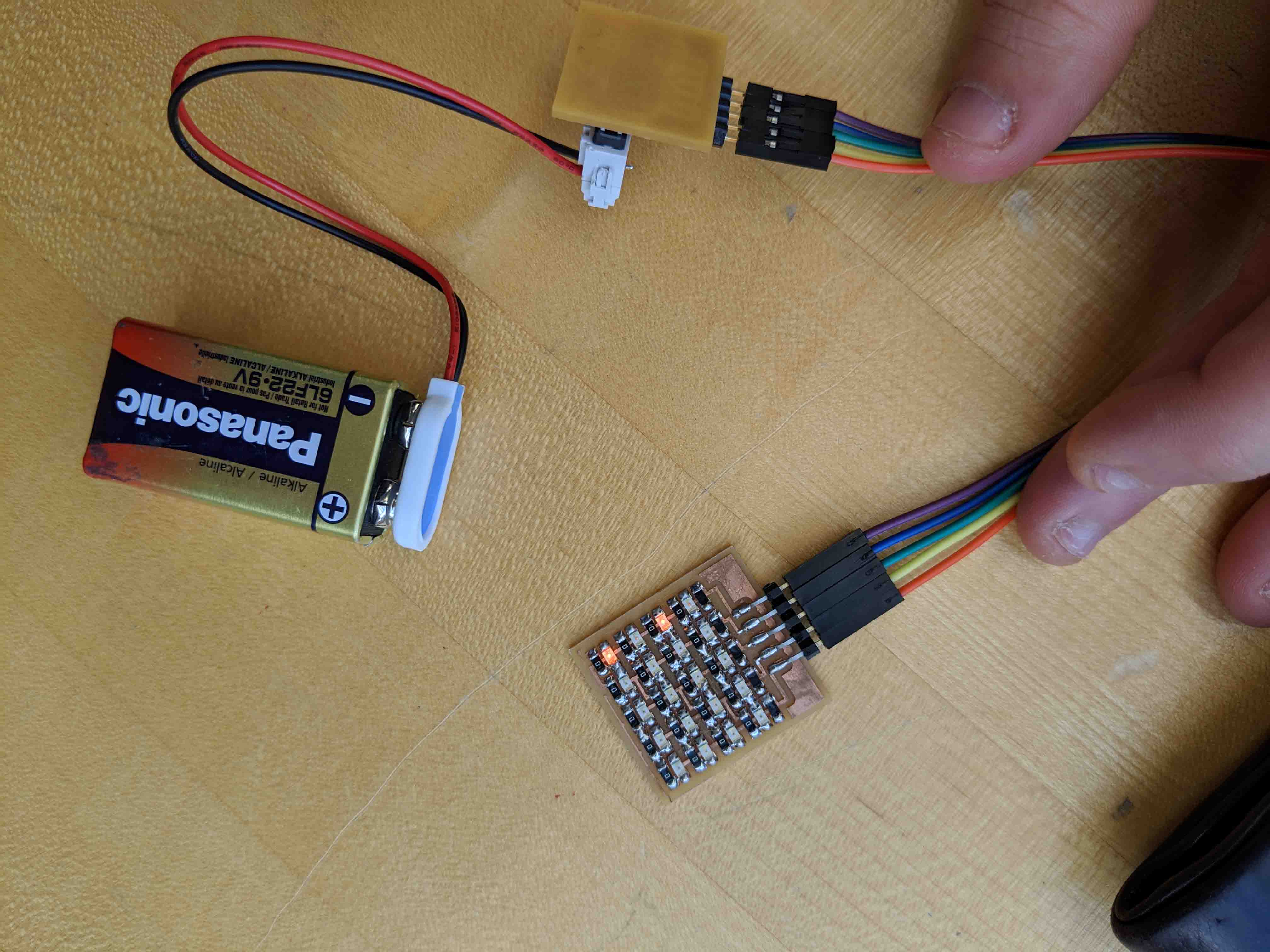
Because my final project idea has taken a turn (see “about” tab for more details on this), I decided to try to start prototyping ideas for my bike light with Neil’s LED array.
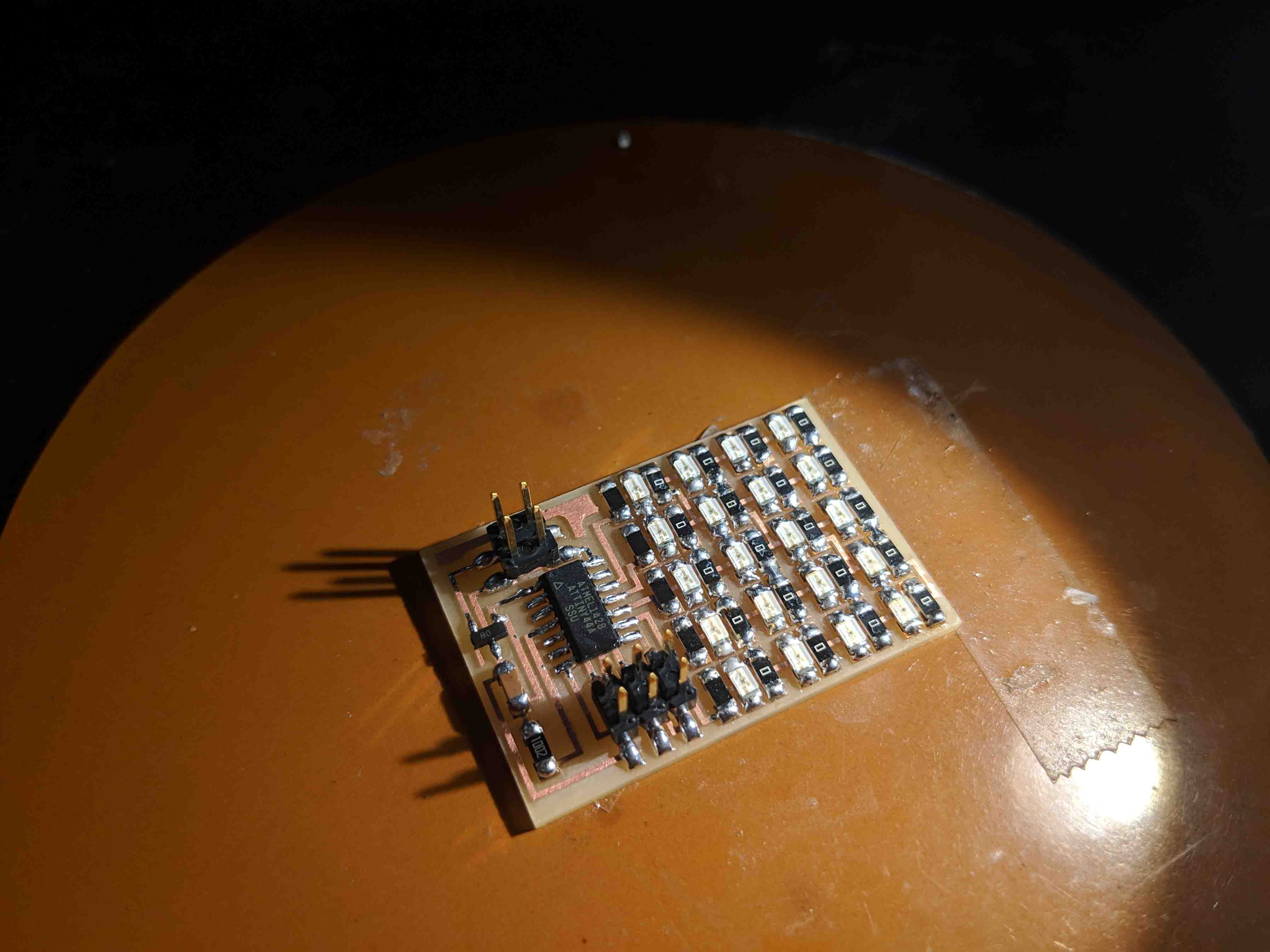
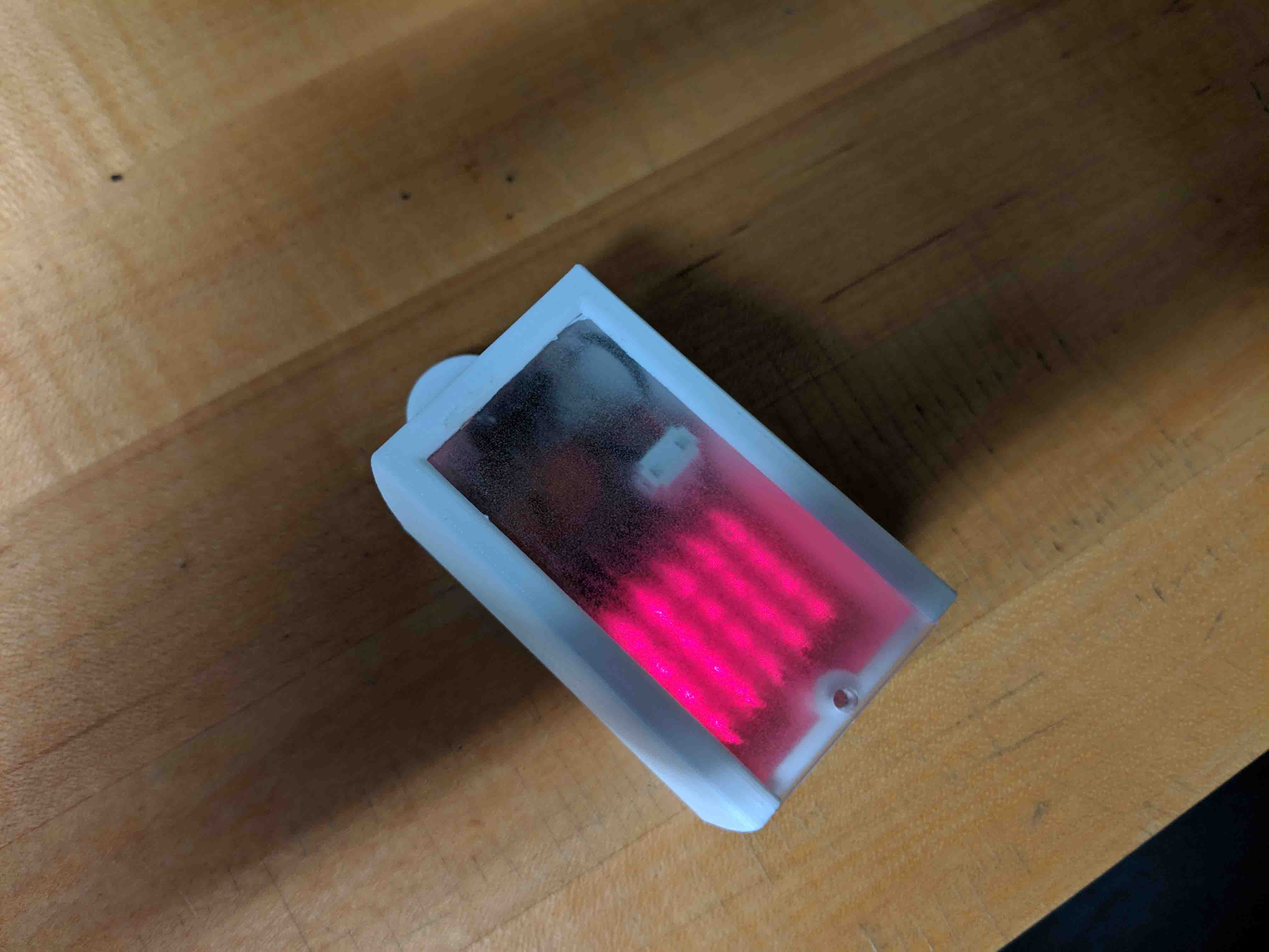
Here, you can see what I ultimately ended up with!
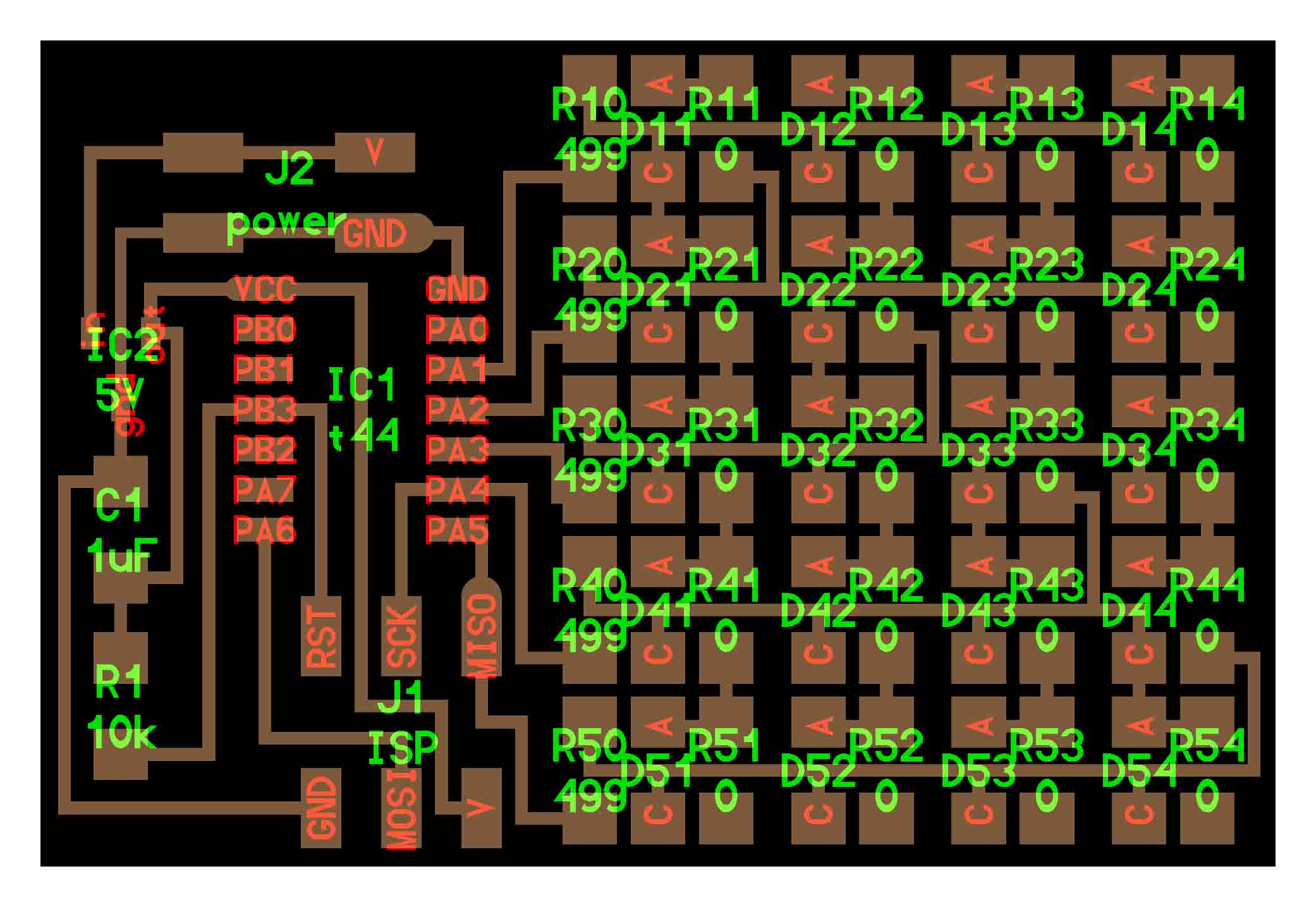
Now, for the nitty-gritty of the week - my struggles with the LED array. I decided to recreate Neil’s “hello.array.44” board, but add a special twist with 3D printing and laser cutting. I have a wonderful blinker light on my Bianchi, but I’ve always wanted a little clip one for my cycling dry bag. I admittedly was more excited with the fabrication side of things for this week than actually coding - but when is that not the case for me, anyways?
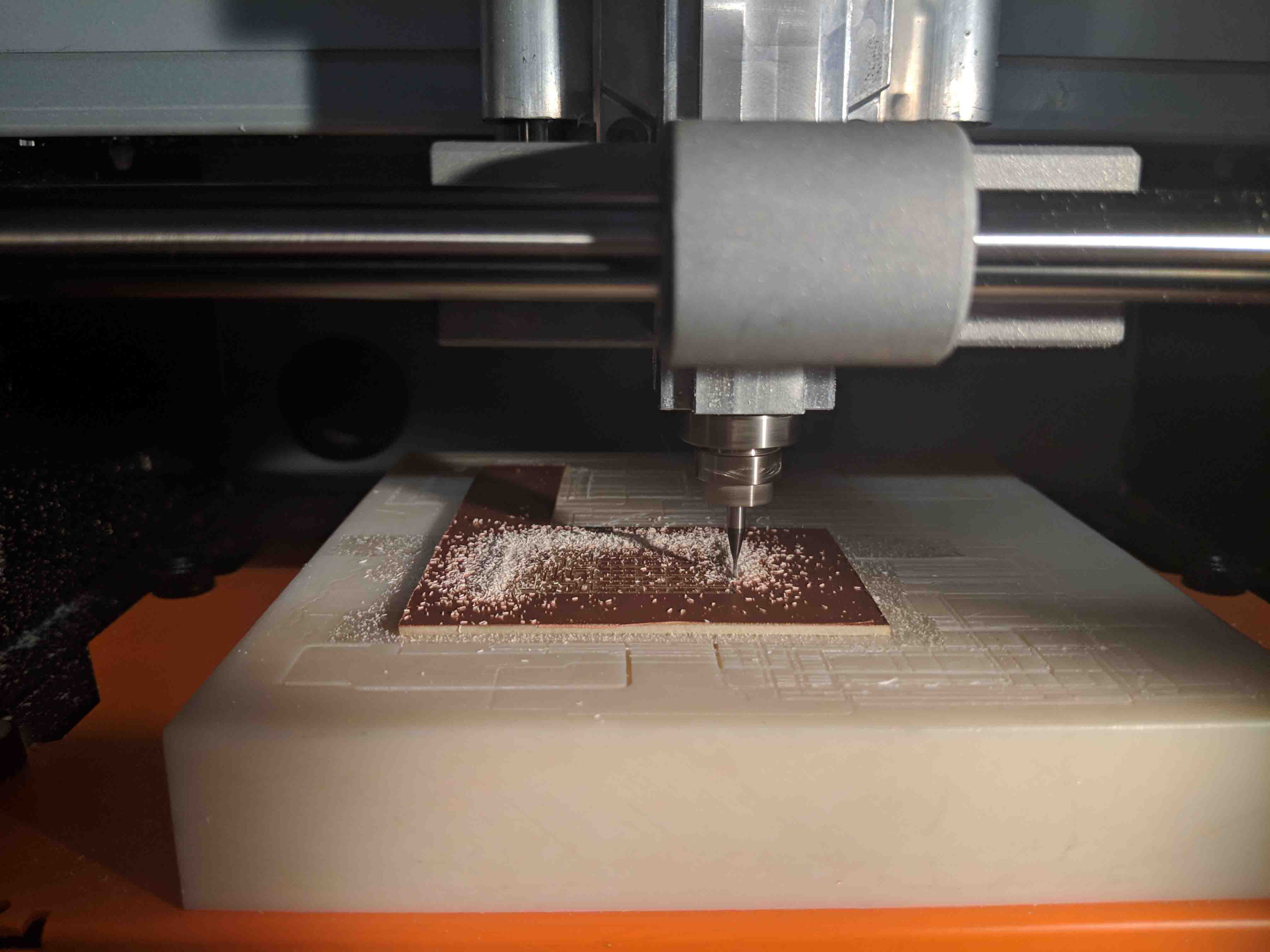
I used Neil’s schematic and PNG files to mill.
As with previous milling exercises, milling was straightforward. Not much to report here. This is all starting to feel second-nature for me.
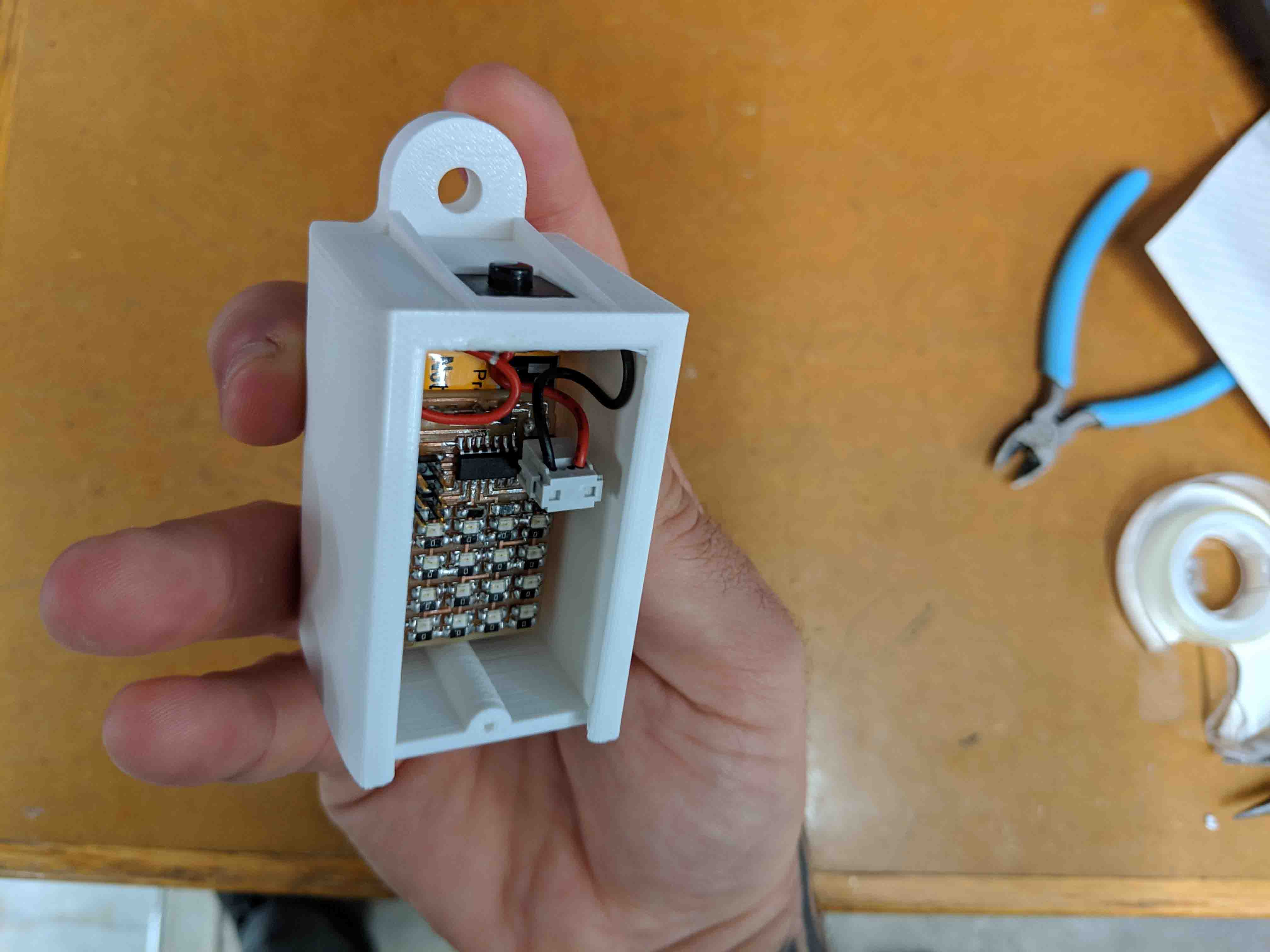
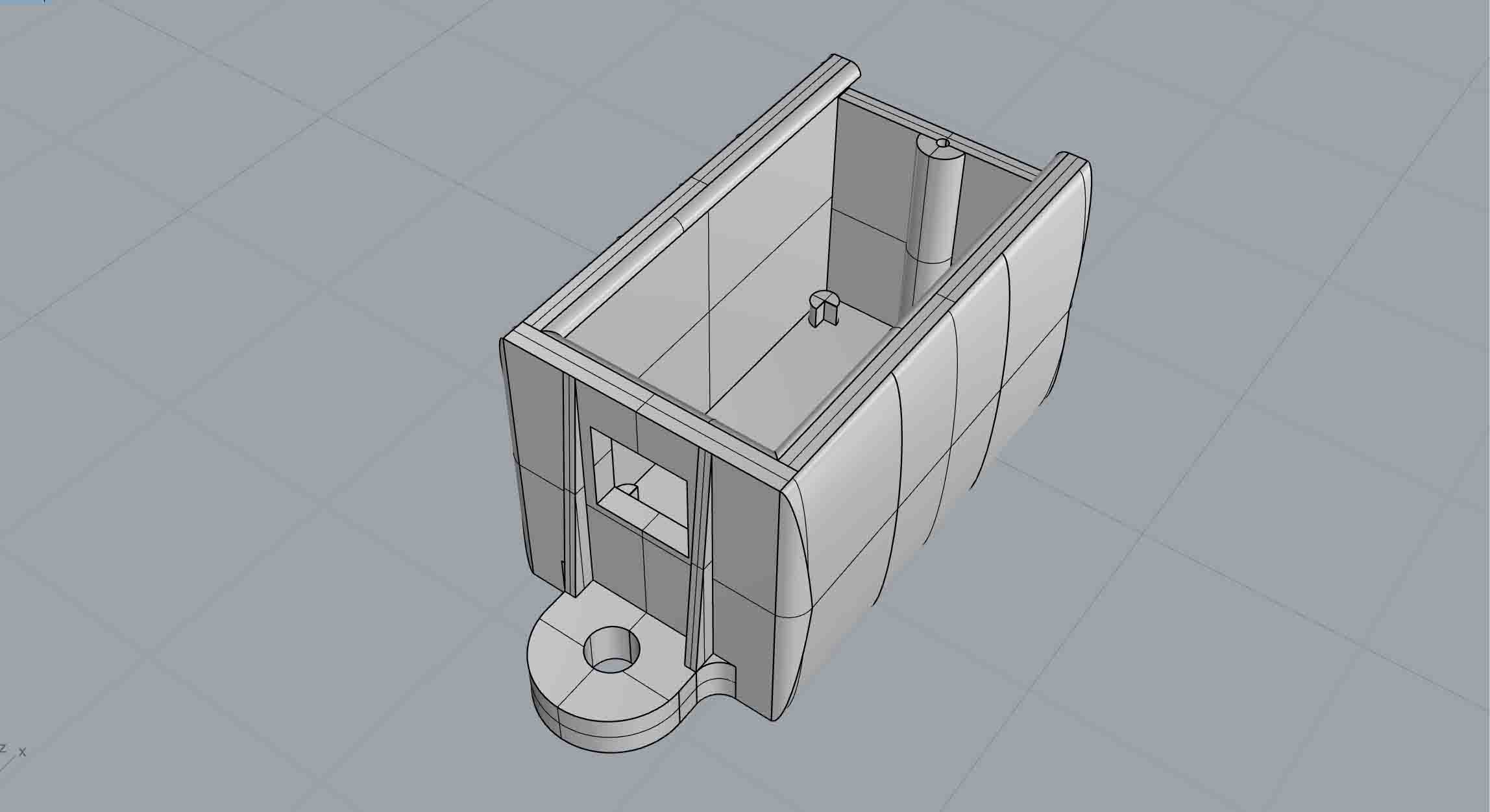
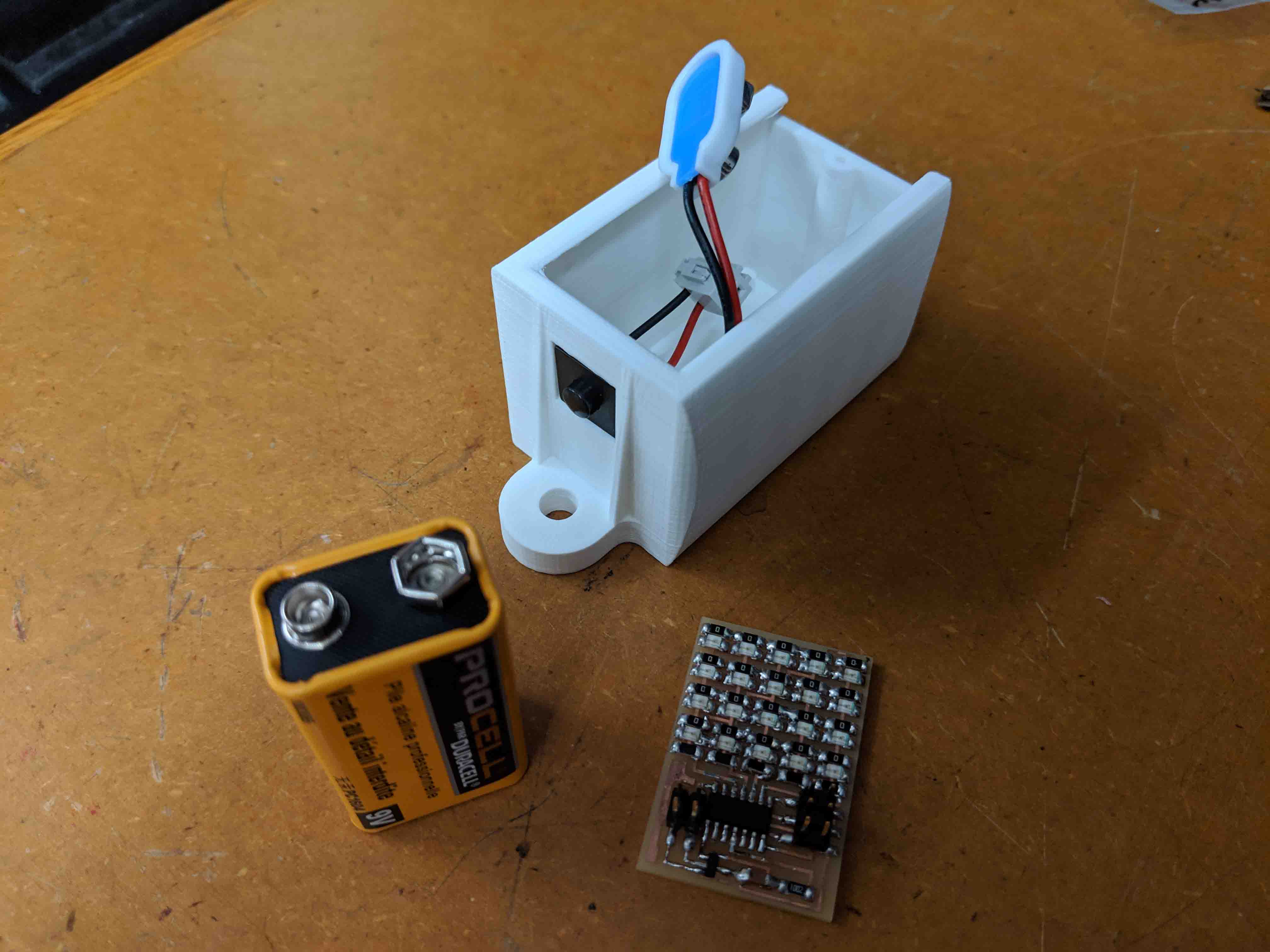
Then I started to design and model the enclosure box for the prototype assembly. I know that I won’t want to rely on a huge 9V power supply for the final project, but for the sake of this model, I had to create a pretty deep box. A small hole for a button was inserted, and little slots to slide a ghosted acrylic cover were also added.
Stuffing was hell. STUFFING WAS HELL. STUFFING WAS ABSOLUTELY HELL. There’s not much to say on this other than I hate myself for doing it and I wish I had used a microscope the first time around before arrogantly assuming that I “had this.” If you’re reading this: find a nice pair of headphones, stay away from tremor-inducing headphones, and expect to go to town for a few hours on nano-scale minutia bullshit.
Sorry.
Rob and I ran into several issues with programming the board, as “avrdude” was unrecognized.
Ultimately, we had to replace the processor three times before I got a good connection. I’m not sure if the ones I had used previously were duds or not. Nonetheless, coding the processor took only 5 minutes or so after we figured all of that out.
Then, it was time to actually assemble everything. A bit of hot glue helped me get in my button solidly.
The battery rested pretty well within the little feet that I had designed for the base, as well.
Because I used Neil’s schematic straight up, I couldn’t bring the LED array too close to the acrylic cover (in light of the thickness/height of the leads going to the 9V power supply). I found that if I rastered the acrylic with a pretty heavy setting, the LEDs appeared to be brighter and more washed out than they actually were. Little tricks go a long way.
I am excited to take this bulky/ugly/hideous thing a step forward. After redesigning the LED array and allowing it to scale down in size, I’m sure I can get this thing to be a small and manageable and cute size.
This week I actually read the schedule to make sure I fulfill the correct assignment.
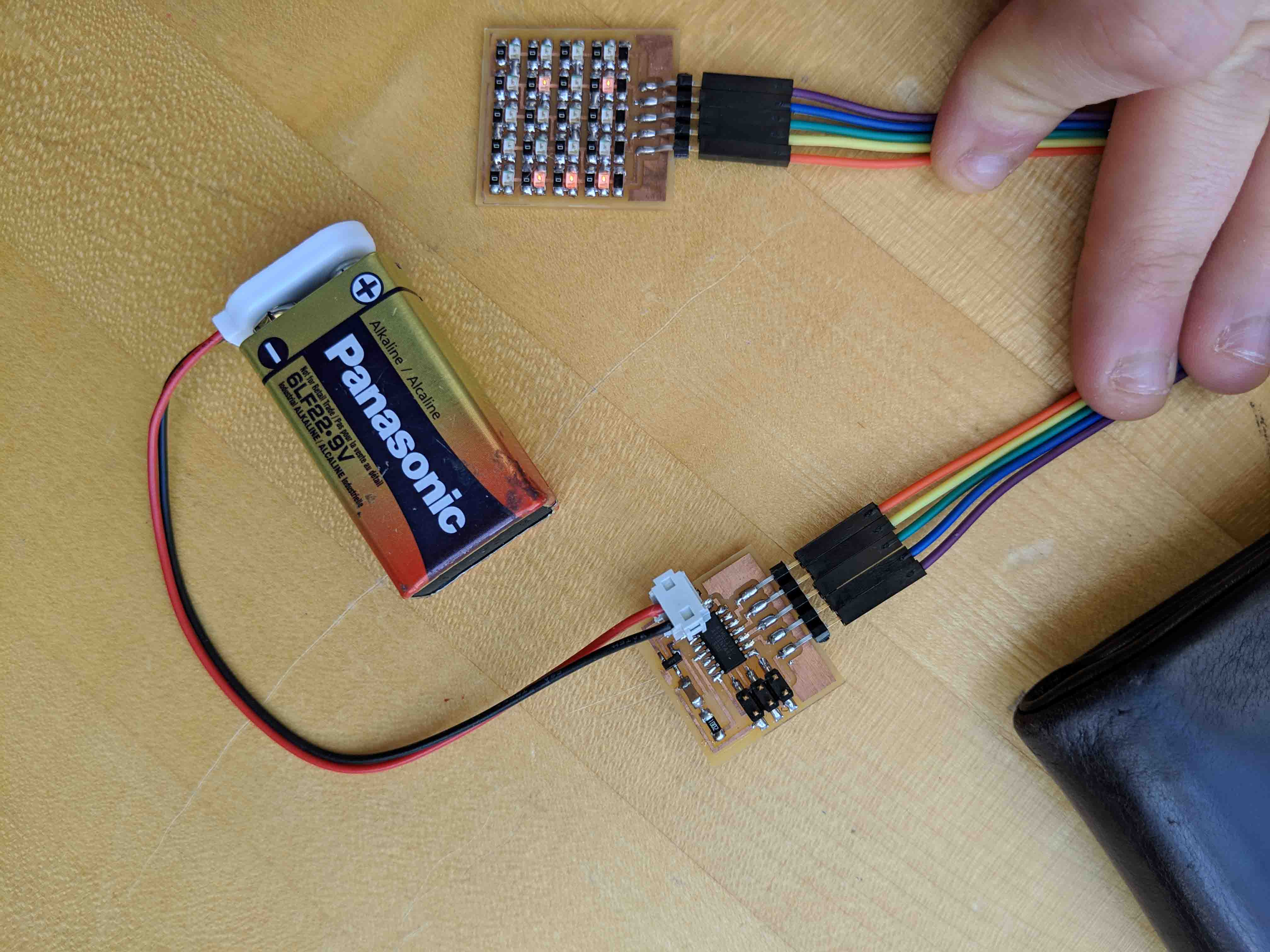
Given last week's shift in final project direction, I thought it best to continue the LED array that I've been developing and start designing my own board and layout. The biggest setback for me from Neil's board was that the board was one solid piece - it made more sense for my applicaiton to split it up into two, with a ribbon cable attaching the two boards, to allow the LEDs to be as close to an acrylic plate as possible.
Pictured below is the final output and my alteration/take on Neil's board for this week!
I figured that by the time I fired up Eagle and started redrawing components, I’d lose too much time. I’m pretty happy with most of the layout of Neil’s board, so I just set out to work in Photoshop to add in a 5-pin header on each board after I split Neil’s board into two. I also moved some things around to make both boards more compact.
Below, you can see the schematic for the processing board:
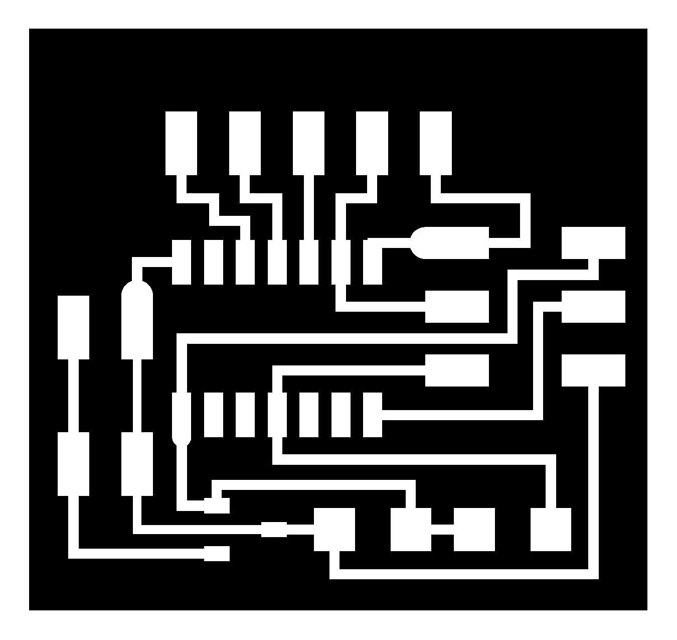
And here you can see the separate board for the LED array and resistors:
Coding has continually been the most daunting part of the process for me, and this week was probably the most frustrating - simply because I was SO CLOSE to getting it done in under 10 minutes, but kept stupidly using “ls” instead of “cd” to my directory. As such, I was at first never able to read my hex file and send it to the board.
Nonetheless, I got that done, and the board worked as expected.
For a next iteration, it might make sense to use a horizontal header for the power component to slim that down.
I would also entertain clipping off the six-pin header after coding, since that renders as moot after the AT44 knows what it’s supposed to do.
This week, we were tasked with creating a machine!
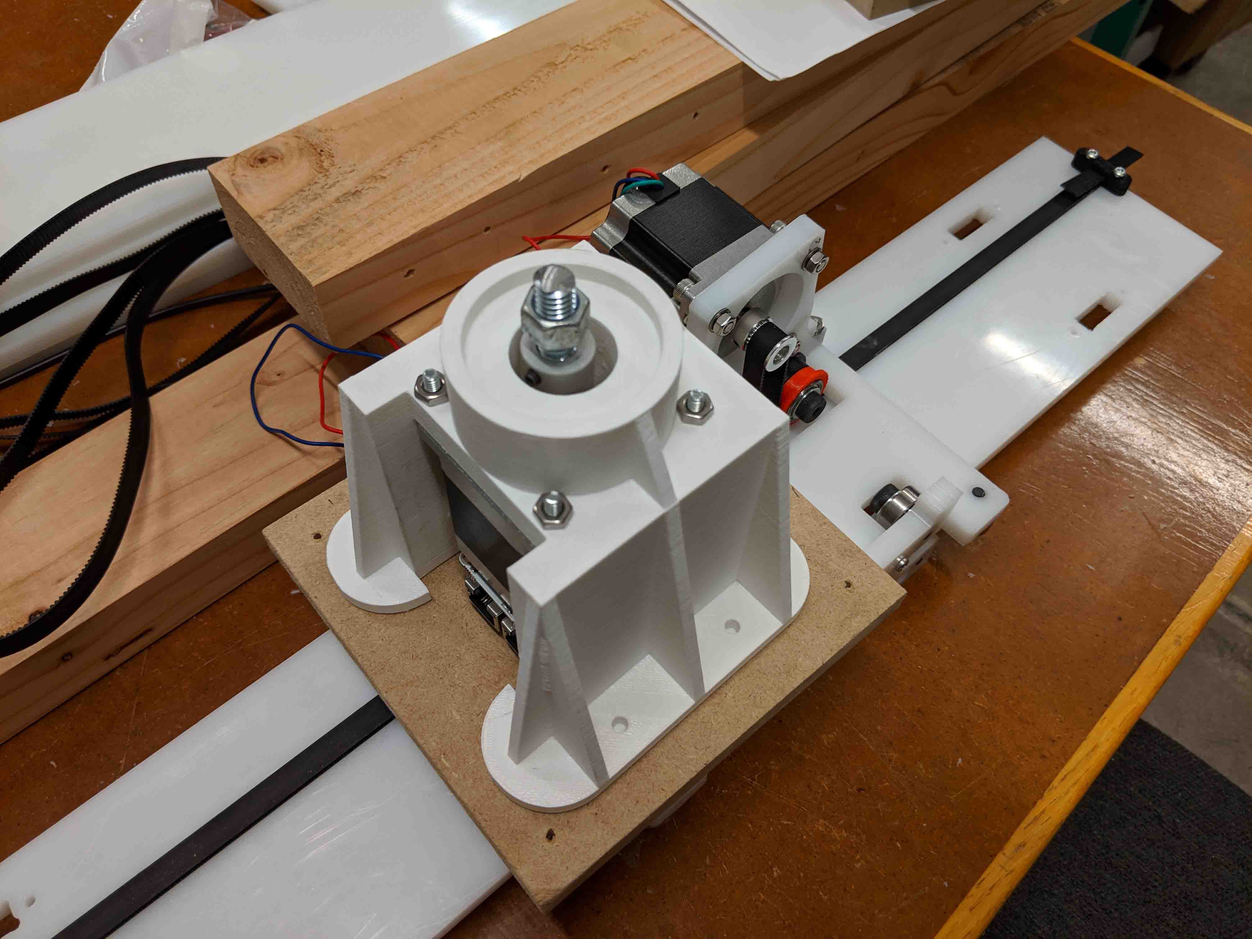
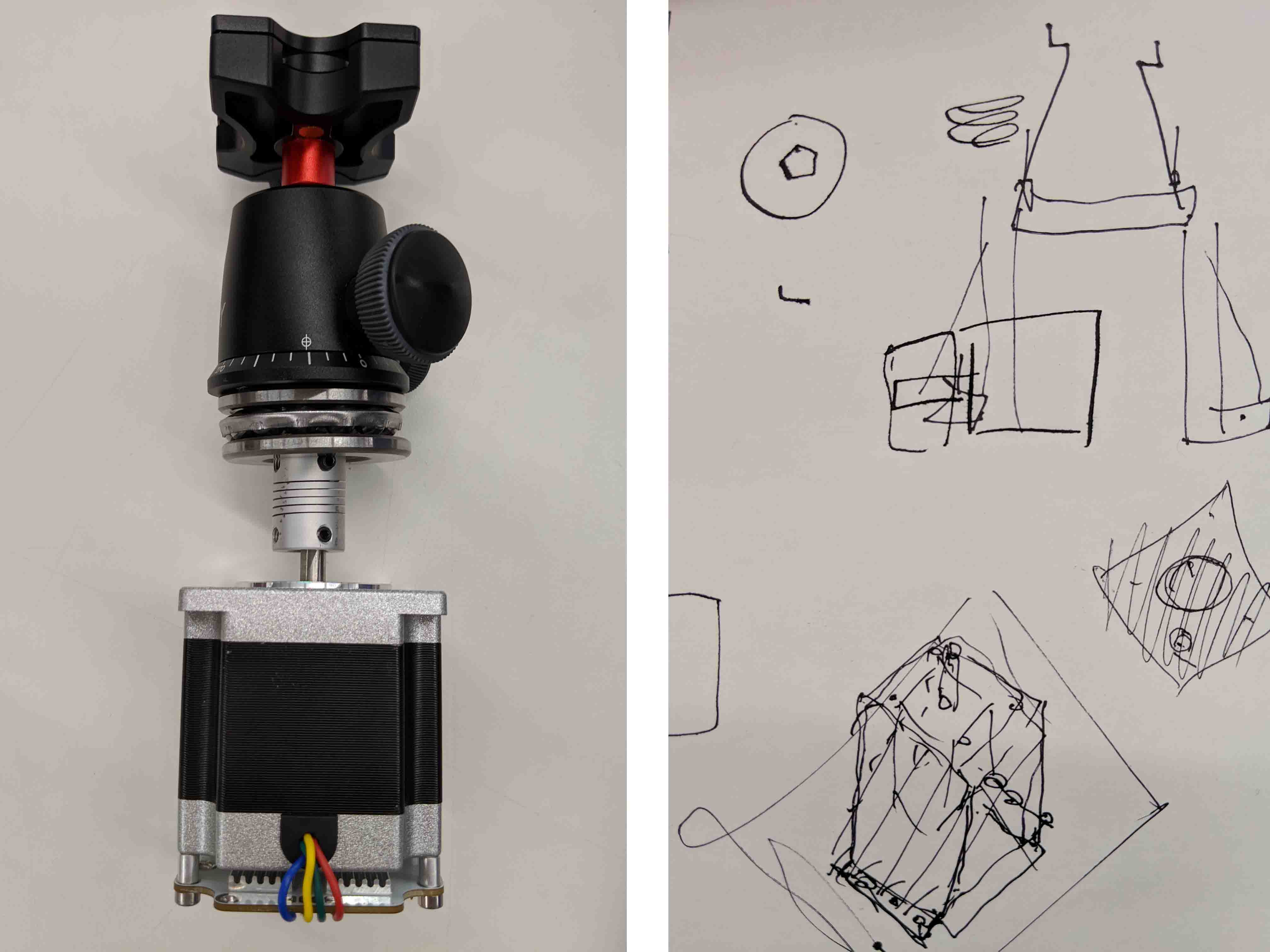
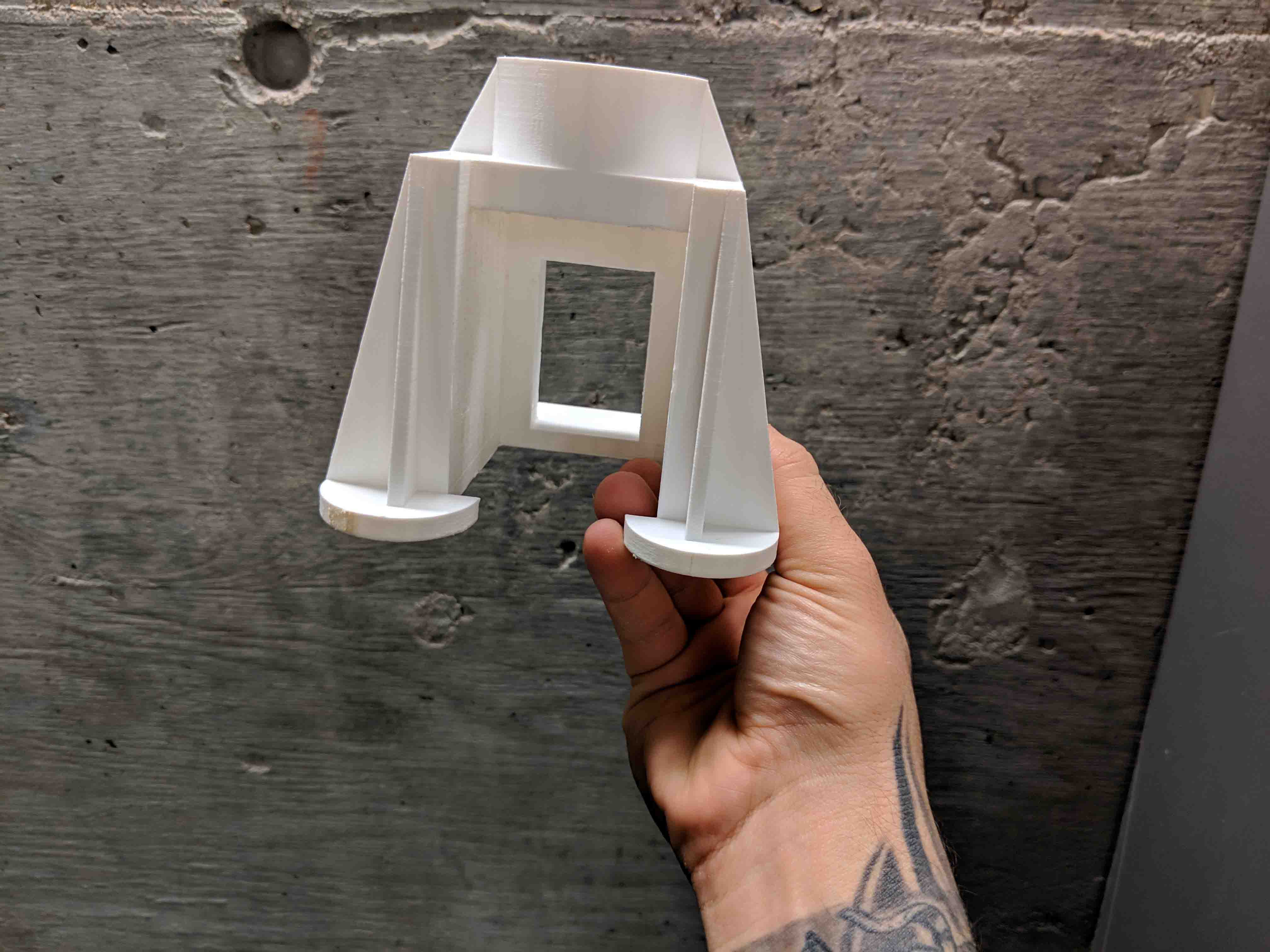
As a group, we decided to make a panning camera track, which relied on two servo motors. My task was to create a housing for the second motor to ensure that the camera could turn in a stabled and controlled manner in the z-axis.
Pictured below is my final design in its installed glory!
I first started from David's original ideas behind how to support the servo and the camera mount he had kindly provided.
As these sketchy sketches show, we were originally thinking to create several press-fit pieces. However, after a bit of discussion, we found it best for me to take David's design and design/print a singular piece out of PLA in order to have the thing be streamlined, strong, and mountable.
After I designed everything, I simply sent it to the Dremel printer at the Harvard GSD.
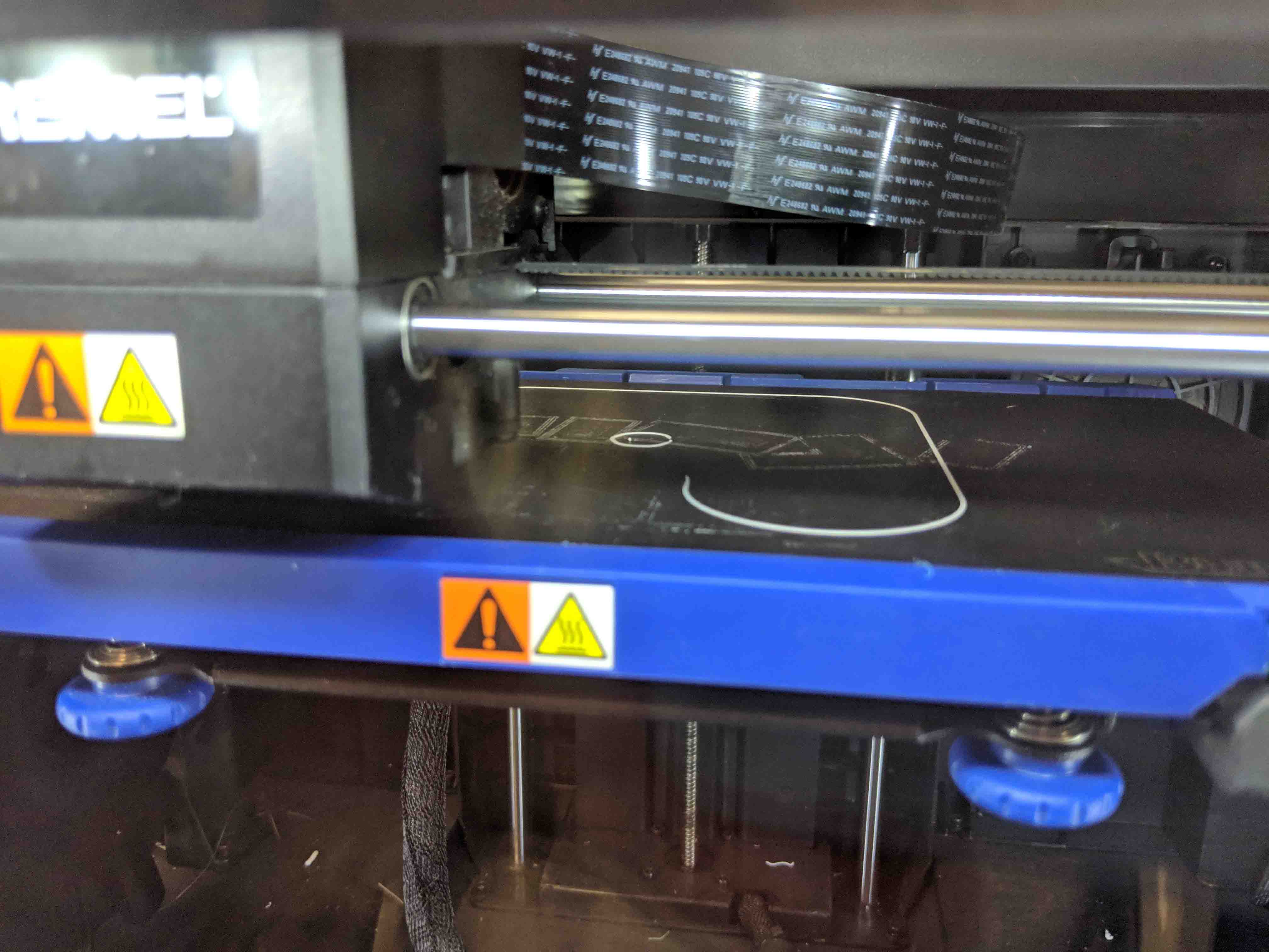
Printing took about 13 hours, so I made sure to keep checking in on my print to make sure it wasn't failing and inadvertently wasting the whole group's time.
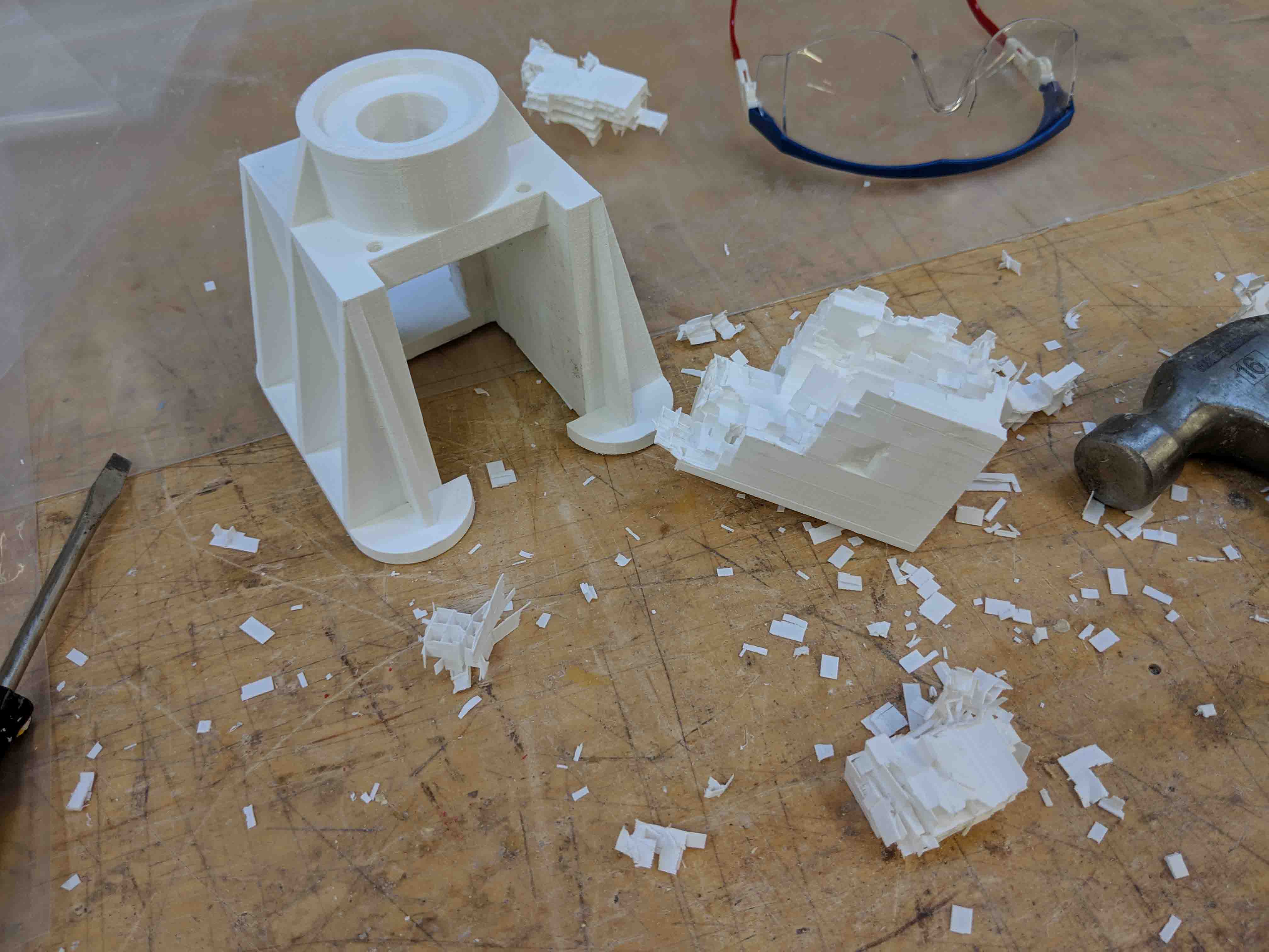
When everything was done, I had to go through the painstaking task of taking support material off.
As you can see, that sucked. This took, in and of itself, about two hours and a few bandaids. But all in all, it worked out.
And here, you can see the final piece!
...and with all of its hardware installed!
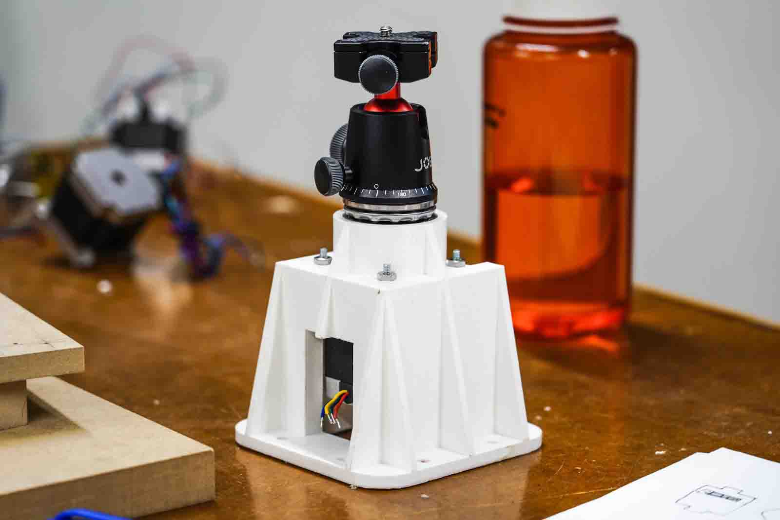
Though I wasn't in class to see the successful run of the machine, I'm glad that this part came together. Next time, I'd probably go a bit easier on the infill, as this part turned out way sturdier than I thought it orginally would.
This week, we were tasked with creating/designing an application through which we could interface with an already-created input/output device. Since I've been focusing so much on LEDs lately, I decided to try to create an application that simply turned my array on and off.
Any coding languages that are stricly text/string based scare the hell out of me, if you haven't realized already. Since I am already pretty good at GH, I decided to give Firefly a try.
Below you can see the final result of everything working! Keep reading to find out more!
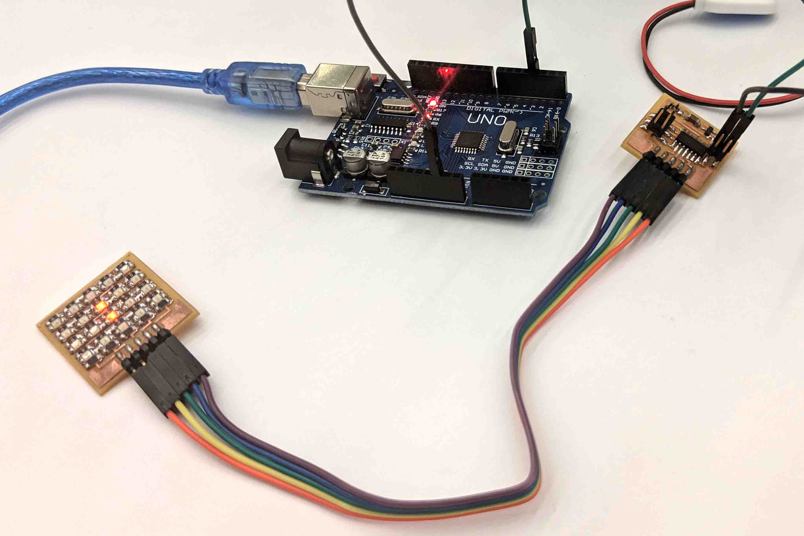
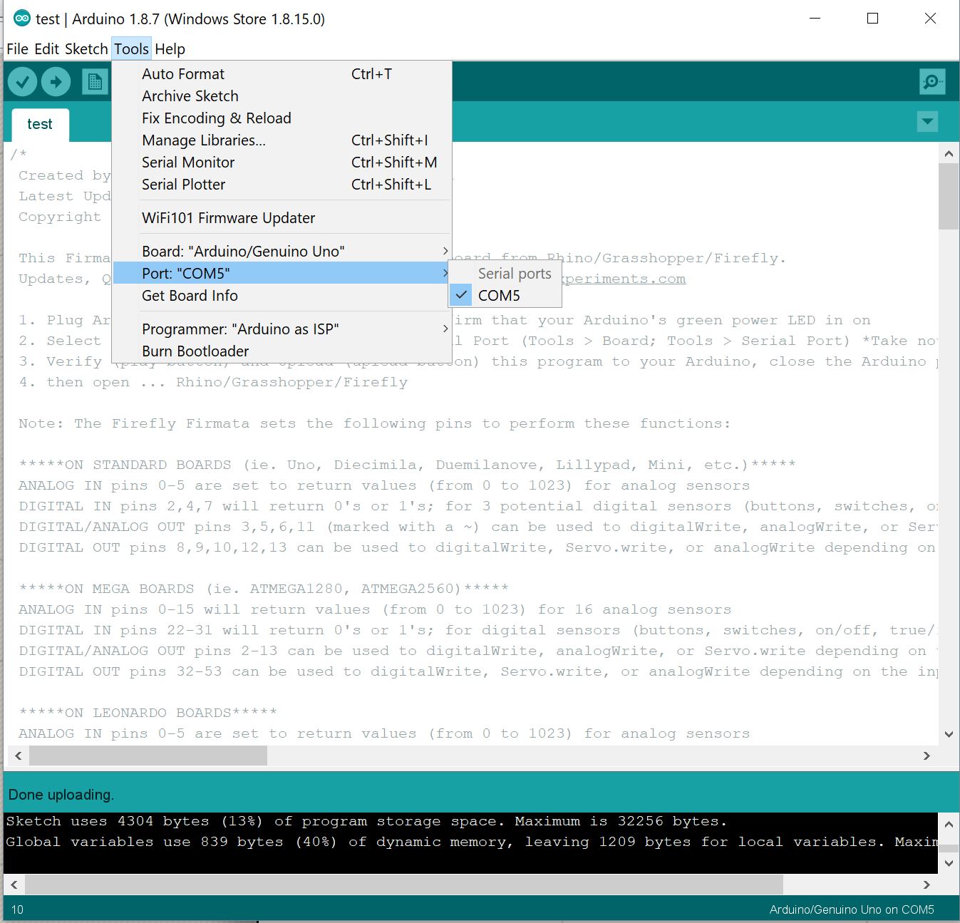
Everything was pretty straight forward. I found a sketch created in 2015 called "Firmata," which I had no problem uploading to my Arduino UNO. I ended up having to use an UNO as I forgot my FABISP in Boston when I went home for Turkeyday, so the Arduino would have to do.
Below, you can see the sketch I used and uploaded:
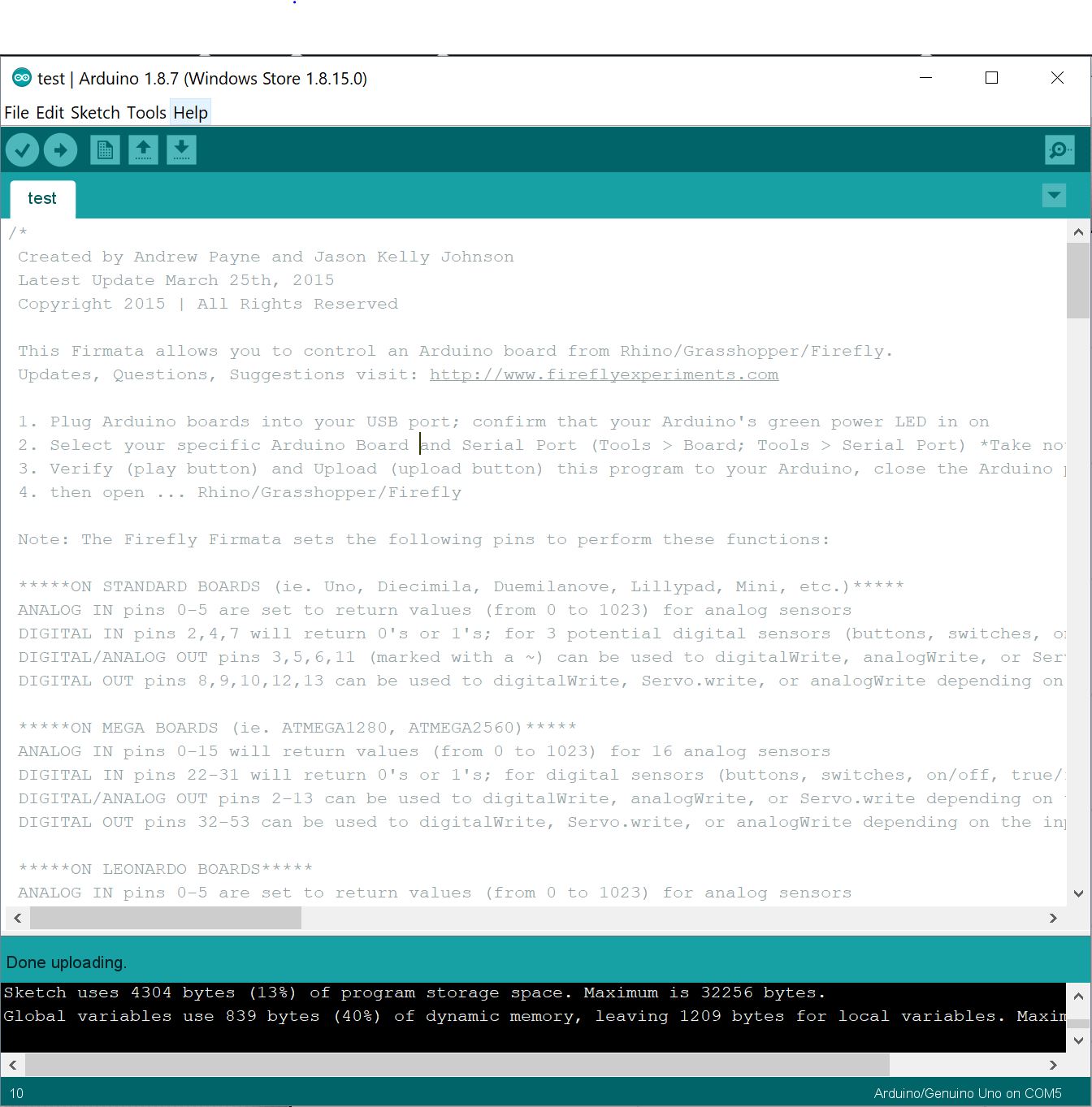
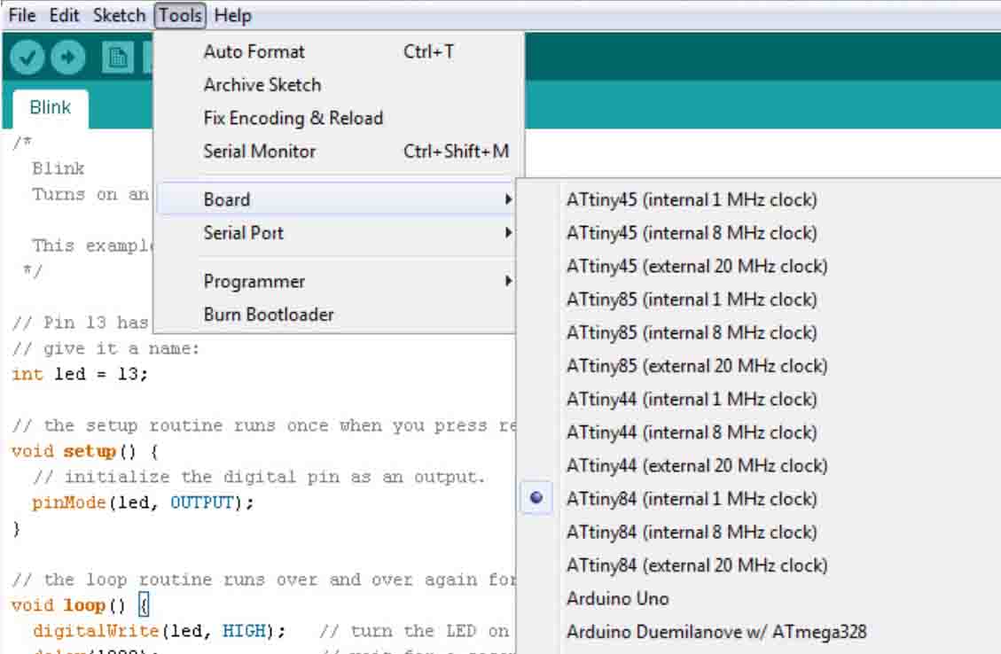
Something I should note is how important it is to know what serial port is being used. I also have to remember to change my board to "Arduino/Genuino Uno" and to use "Arduino as ISP" for the programmer.
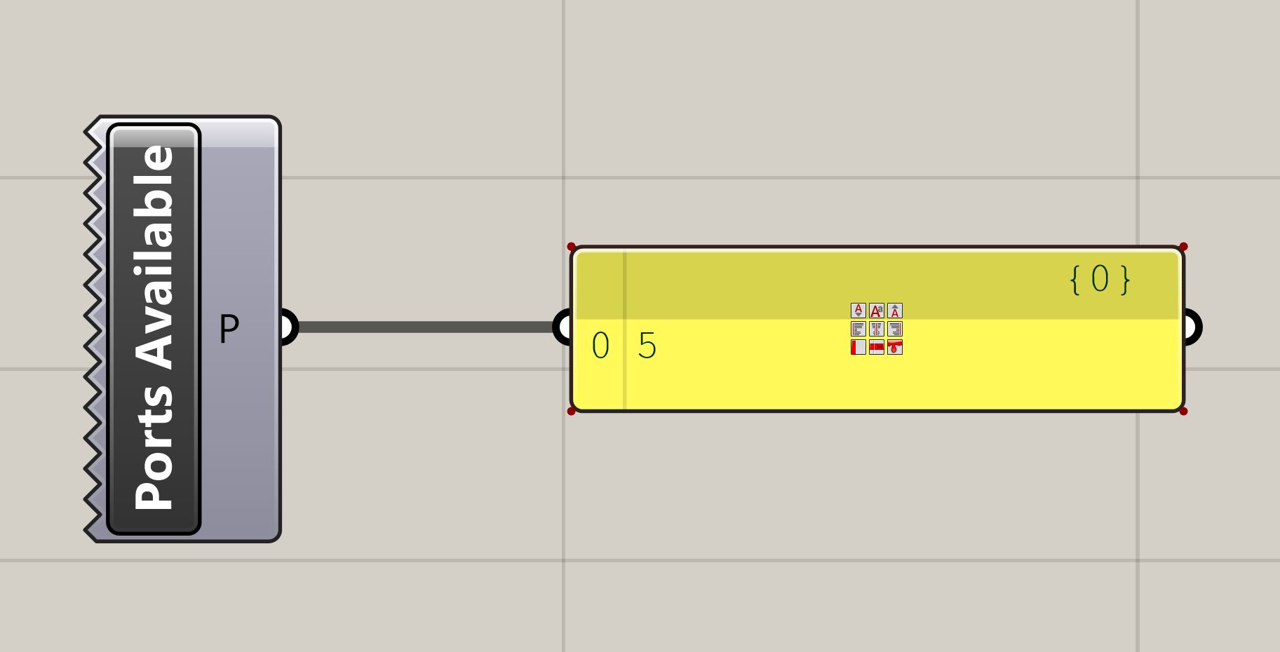
After I sent the code to the board, I booted up Rhino and GH, and brought up the "Ports Available" component to make sure that the port readout in Arduino IDE matched what GH was seeing. I threw in a panel to double check, and was successfully seeing "5" as my port. Great!
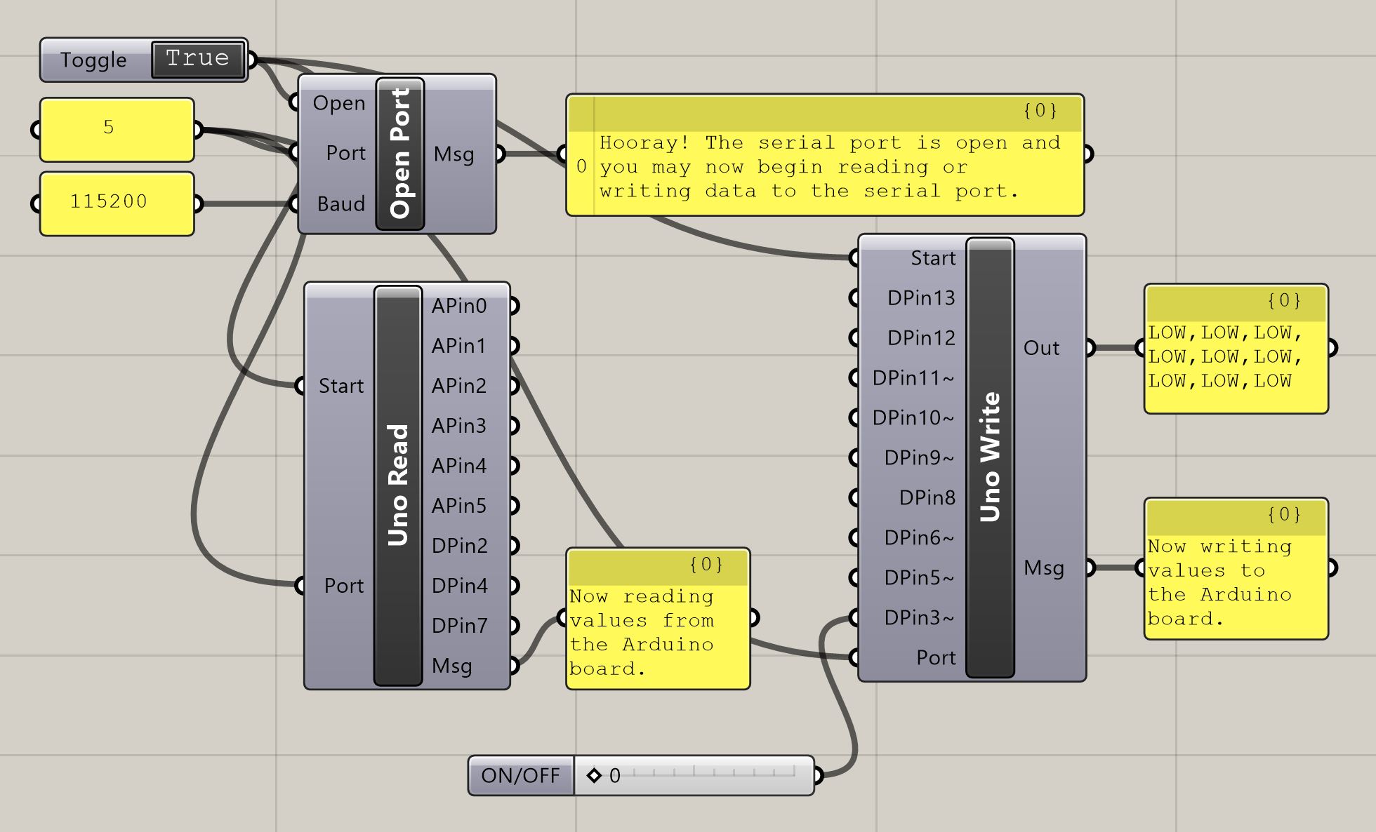
Then, it was time to actually make the sketch. I brought in the "Open Port" "Uno Read," and "Uno Write" buckets, while making sure to attach panels to everything to be able to read everything and the status updates of each port. I also attached a boolean toggle to actually trigger the communication interface, as well as a number slider to turn my LEDs on and off.
I also made sure to enter in the same number that "Ports Available" gave me into "Port," and "115200" into "Baud" because that's what I saw in the script I uploaded to the Arduino IDE.
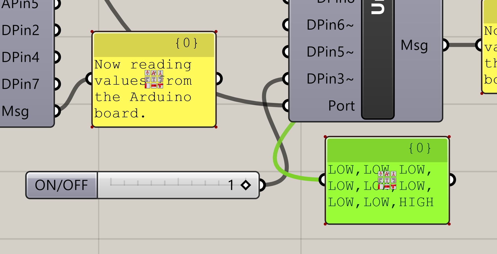
Here, you can see the effect of switching from 0 to 1. The pin I chose to alter - in this case, Digital Pin 3, turns to high, and is live.
All I had to worry about for wiring was attaching ground from my fabricated PCB to ground on the UNO, and connecting power to Pin 3.
And, as you can see, success! Feels a bit silly to toggle a board on and off through a software interface instead of a button, but this certainly opens up the doors to multiple possibilities for interfaces and applications. For now, I'm just glad I got Firefly to communicate so easily.
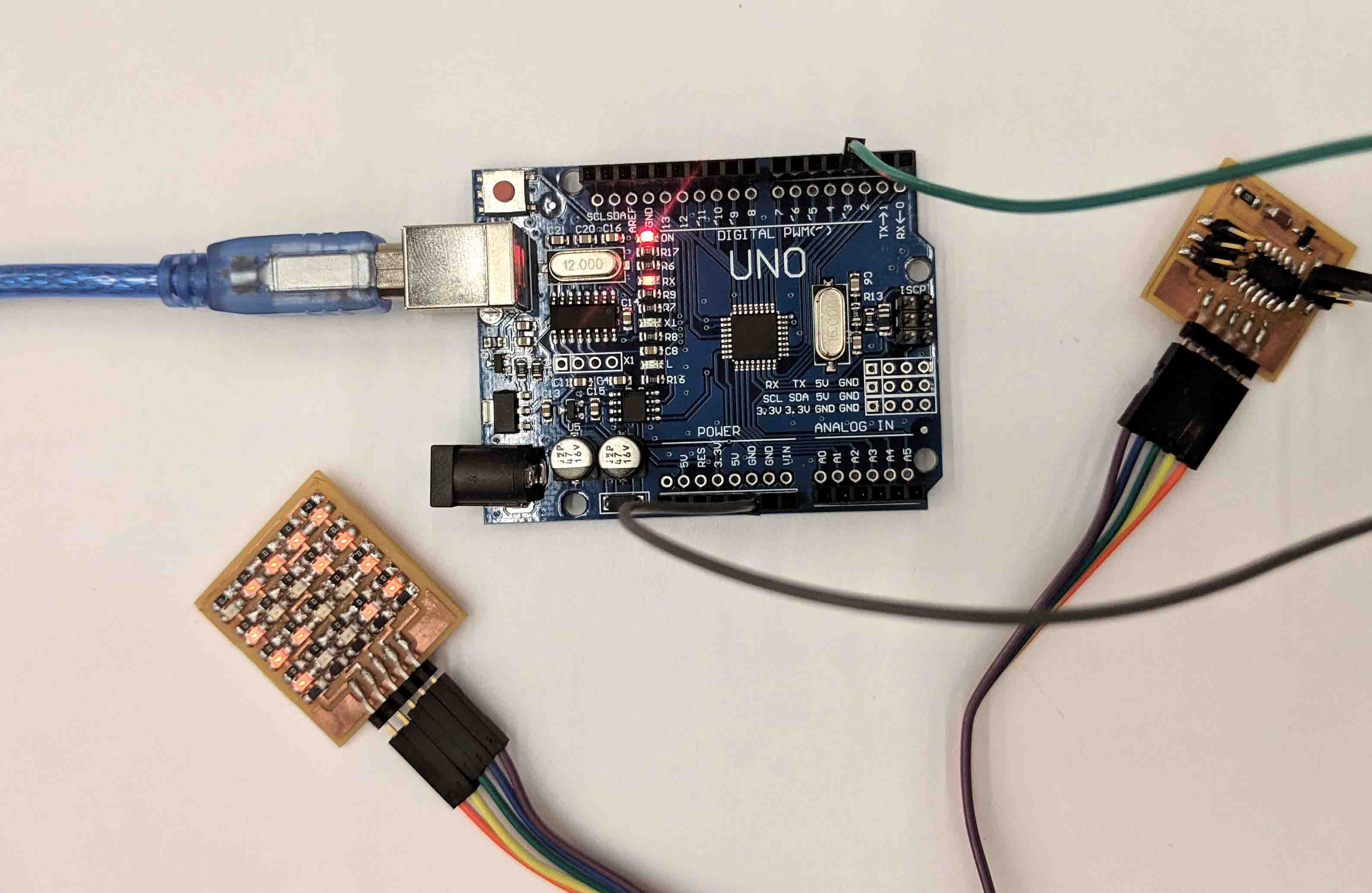
This week, we had to design and construct a wired or wireless network/bus-based network. I decided to combine several previous projects and create a simple thing which transfers an LED signal with the push of a button.
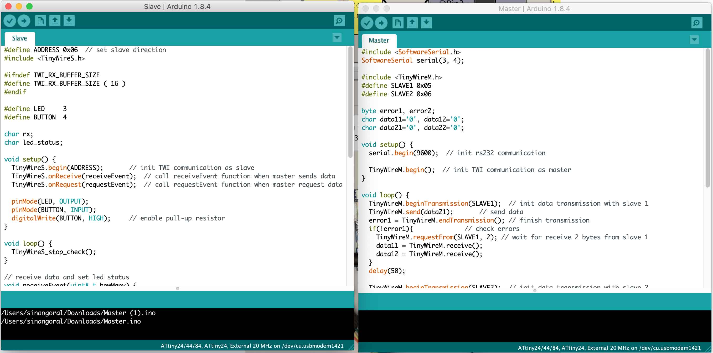
The Arduino IDE was used to load up my code, to both the master and slave boards.
I based the boards off of Neil’s base, combined with the previous projects I mentioned.
Below, you can see the master and slave. Keep in mind that there were two slaves used.

Something I should note is how important it is to know what serial port is being used. I also have to remember to change my board to "Arduino/Genuino Uno" and to use "Arduino as ISP" for the programmer.

After connecting and programming, I was able to get power to each of the boards and start to transfer the LED signal between the two slaves.
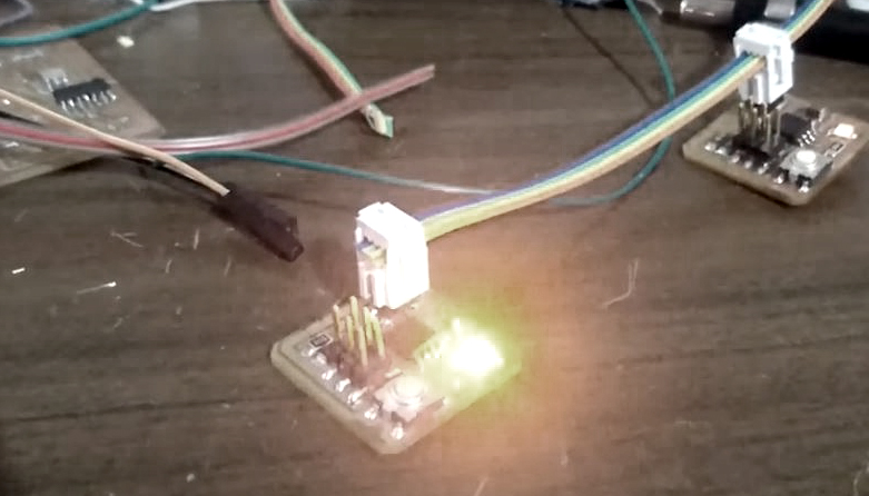
Here you can see this transfer a bit more clearly.
This week, we were all given the opportunity to pursue one of a myriad of learning objectives. Given my recent interest in sewing/knitting, I joined the “Machine Knitting” group led by the awesome team of Alexandre Kaspar and Paloma GR.
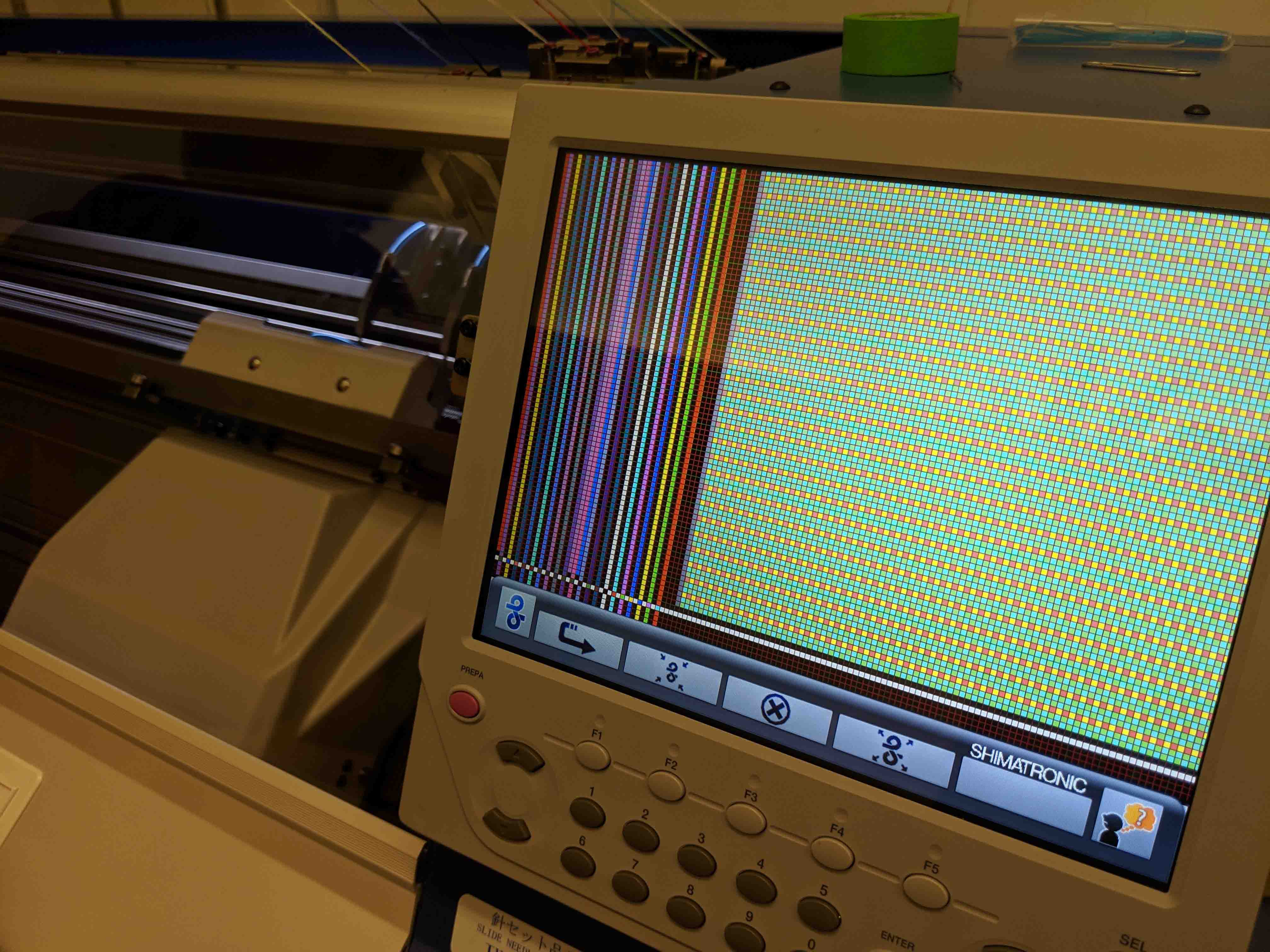
This was a hilariously confusing week, so forgive me if I can’t explain things right. I’ll be trying my best. For starters, the strangest thing was that we had to draw our final designs as an indexed PNG, and feed this into the proprietary software through the lab computer. The final document we procured had weaving pattern instructions on both the left and right hand sides of the source image, as you can see below. Since I adore my cat Jack, I decided to make his face. After quickly image tracing a photo of him and reducing the colors to just three, I created the template file, below.
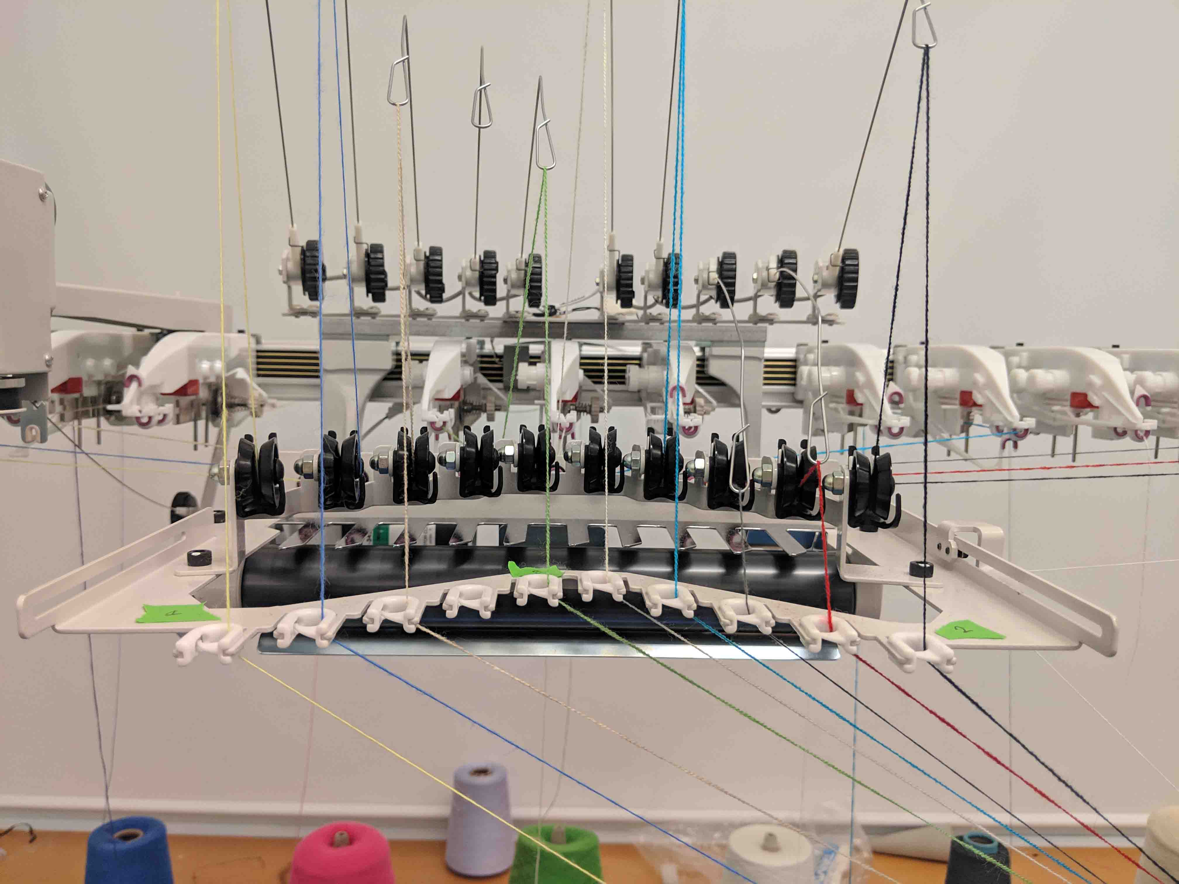
The machine itself looks very much like a plotter, with a complex overhanging carriage above. The spools of yarn are behind the machine, and their threads are wound up through the hanging carriage and down into the right side of the machine. A little touchscreen monitor also lies on the right side, and is the main control interface with which a user can interact with the knitting machine.
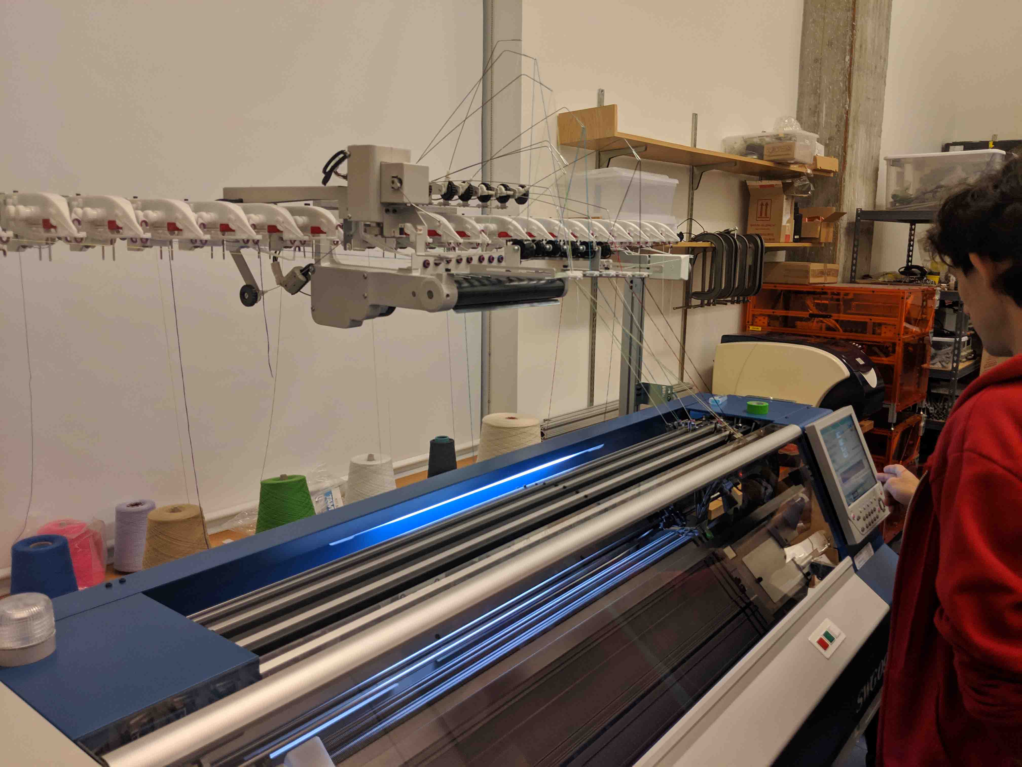
The knitting machine itself was a Shima Seiki WholeGarment SWG091N2 with 15 gauge needles (i.e. 15 needles per inch), and we used acrylic yarn, specifically Tamm 2/30. As you’ll see, Alexandre and I struggled big time with getting anything to work, but I originally started with three colors of yarn - pink, blue, and grey.
Below, you can see the interpretation that the machine has of my input PNG and the instructions on the left and right sides of the document.
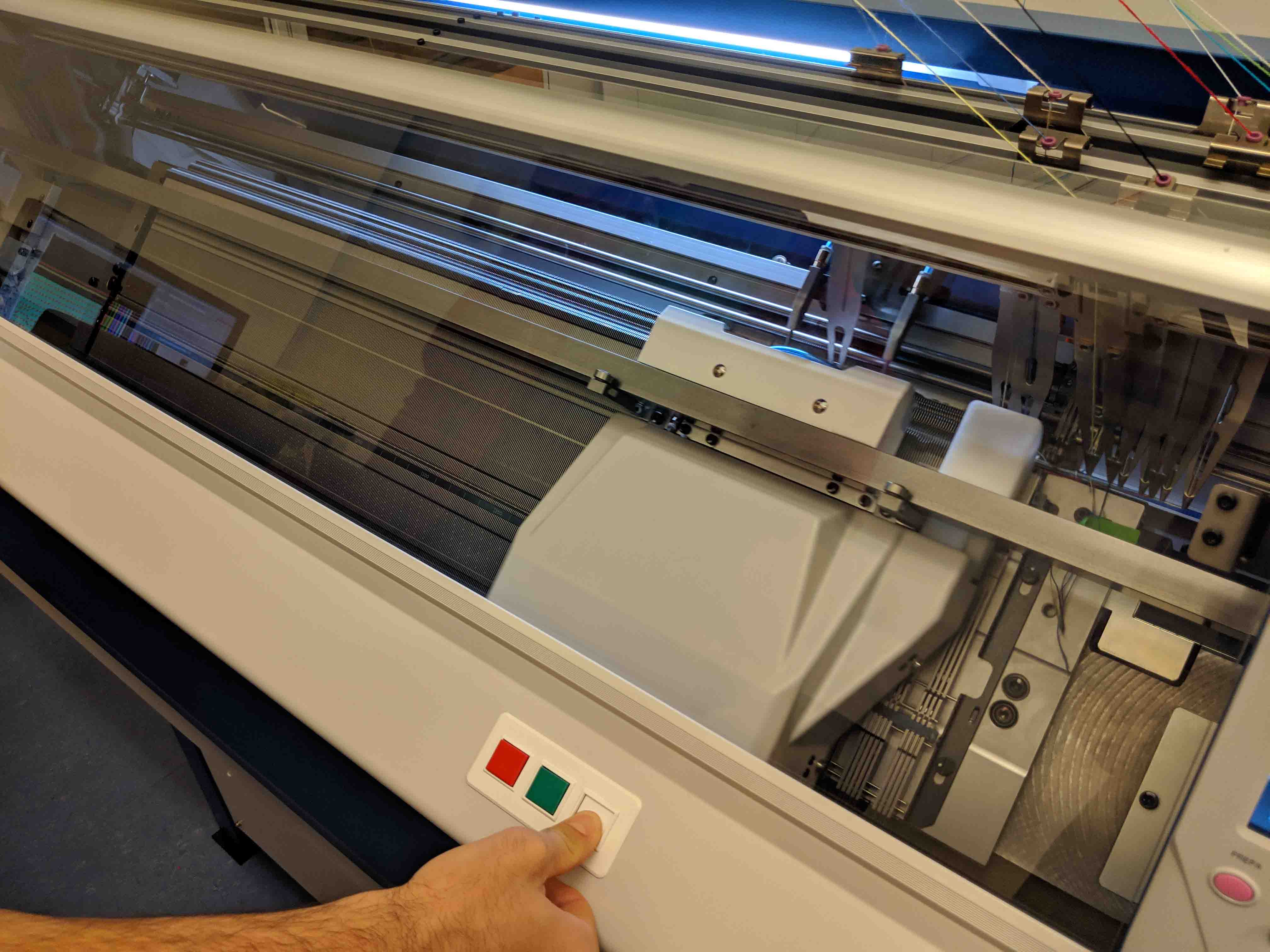
The actual carriage is quite beautiful. The clamor and clanging of the machine while it’s running, combined with the tensioning and detensioning of the yarn arms, makes for quite an interesting experience. It almost looks like a musical instrument in action.
Alexandre and I used the manual override button at first while the machine knit the first few layers. He explained to me that this setting runs things at half the capacity speed of the machine. Later on, we engaged in autonomous mode by pressing the green button.
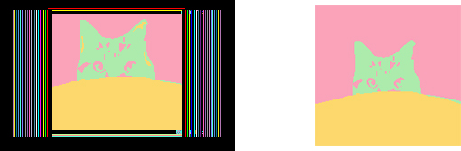
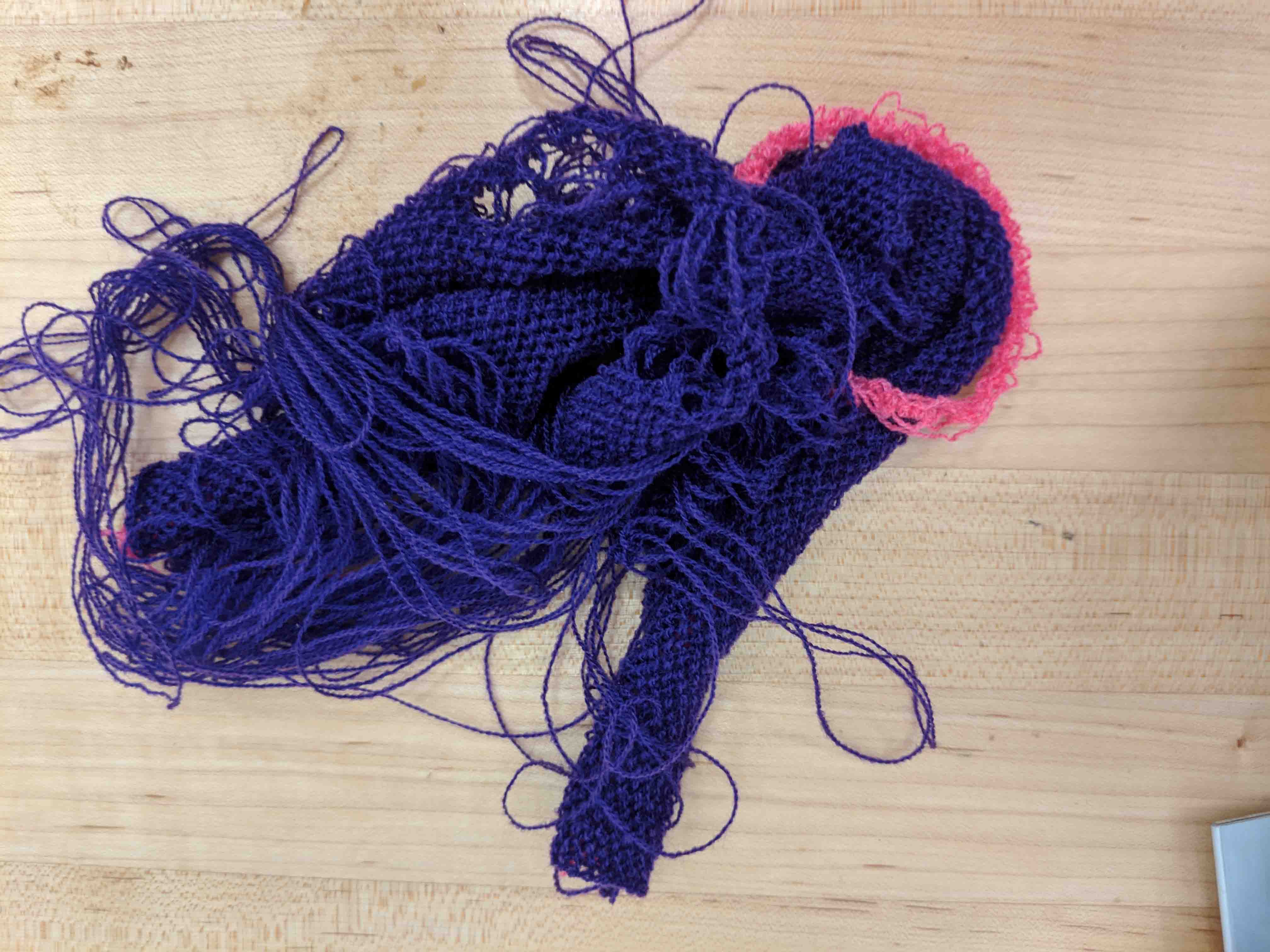
The first few outcomes were truly miserable.
In the first, and to our dismay, the machine had never successfully knit the first layer. As such, every layer thereafter rendered moot, and was more like loose thread.
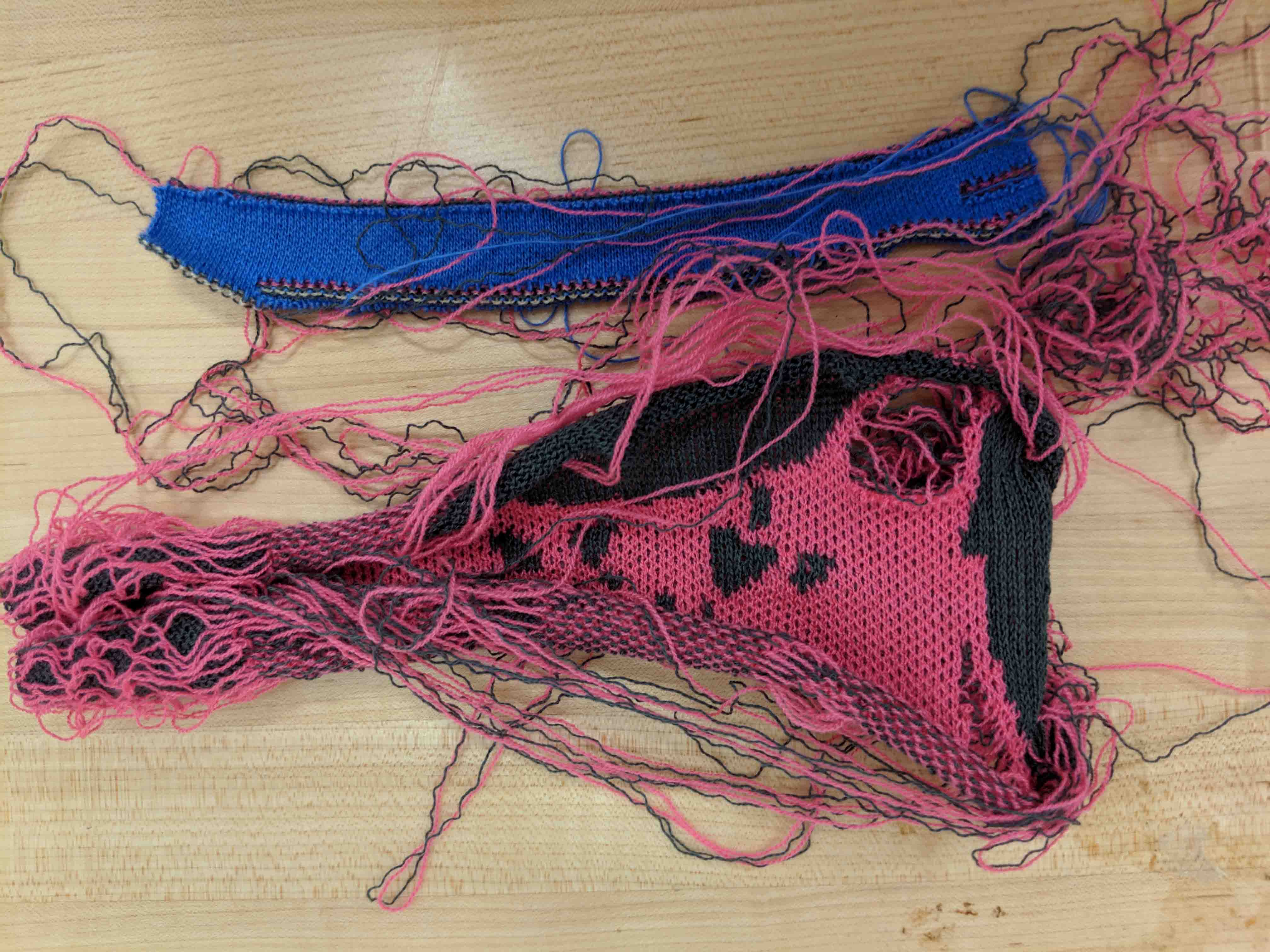
When we tried to distill the image down to two colors, we had an issue with the second color (pink) being too weak and not weaving into and within the other color (grey). This also had a disastrous outcome.
But finally, once we finessed the right two colors (blue and purple seem to be adequately strong), we were able to make Jack’s face!
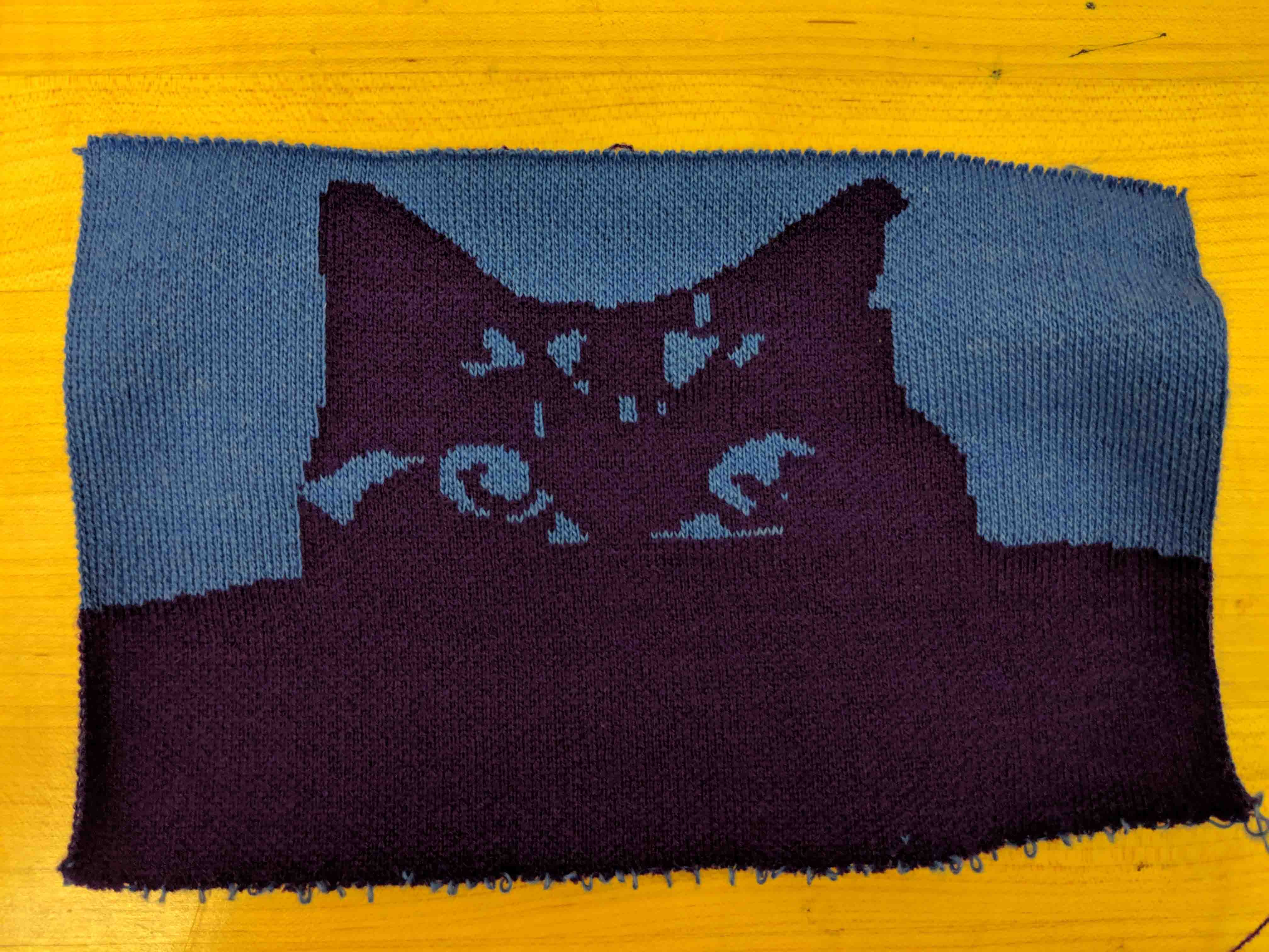
What’s amazing to me is that this whole thing took about 7 minutes to produce. How it actually knits this fast is beyond me. The utmost thanks and gratitude to Alexandre for his expert patience and time!