Week 11: Networking and Communications
Individual Assignment: design, build, and connect wired or wireless node(s) with network or bus addresses
I want to connect my two lamps together via bluetooth. That's the plan at least. So I took to creating a bluetooth board this week using the RN4871. Gil was kind enough to show me a few resources he found helpful--one from Rodrigo Cesarman, one from Jim Peraino. I decided to follow the steps pretty closely to just get a board under my belt. A few days later and a scorched RN4871 chip later, I'm still trying to debug. But here's the process as it panned out chronologically.
Deisgning and Manufacturing
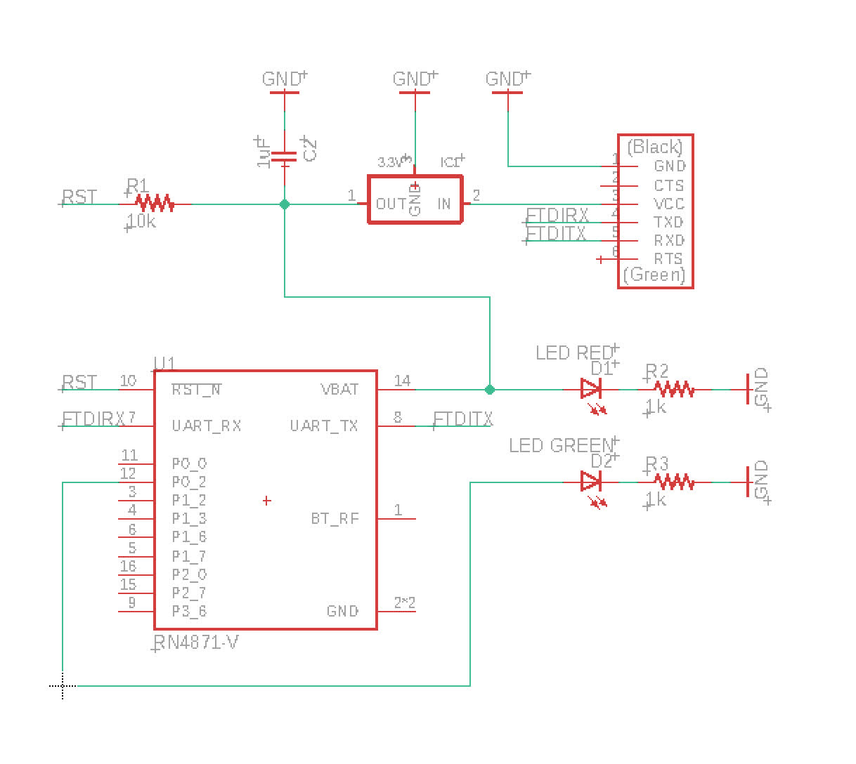
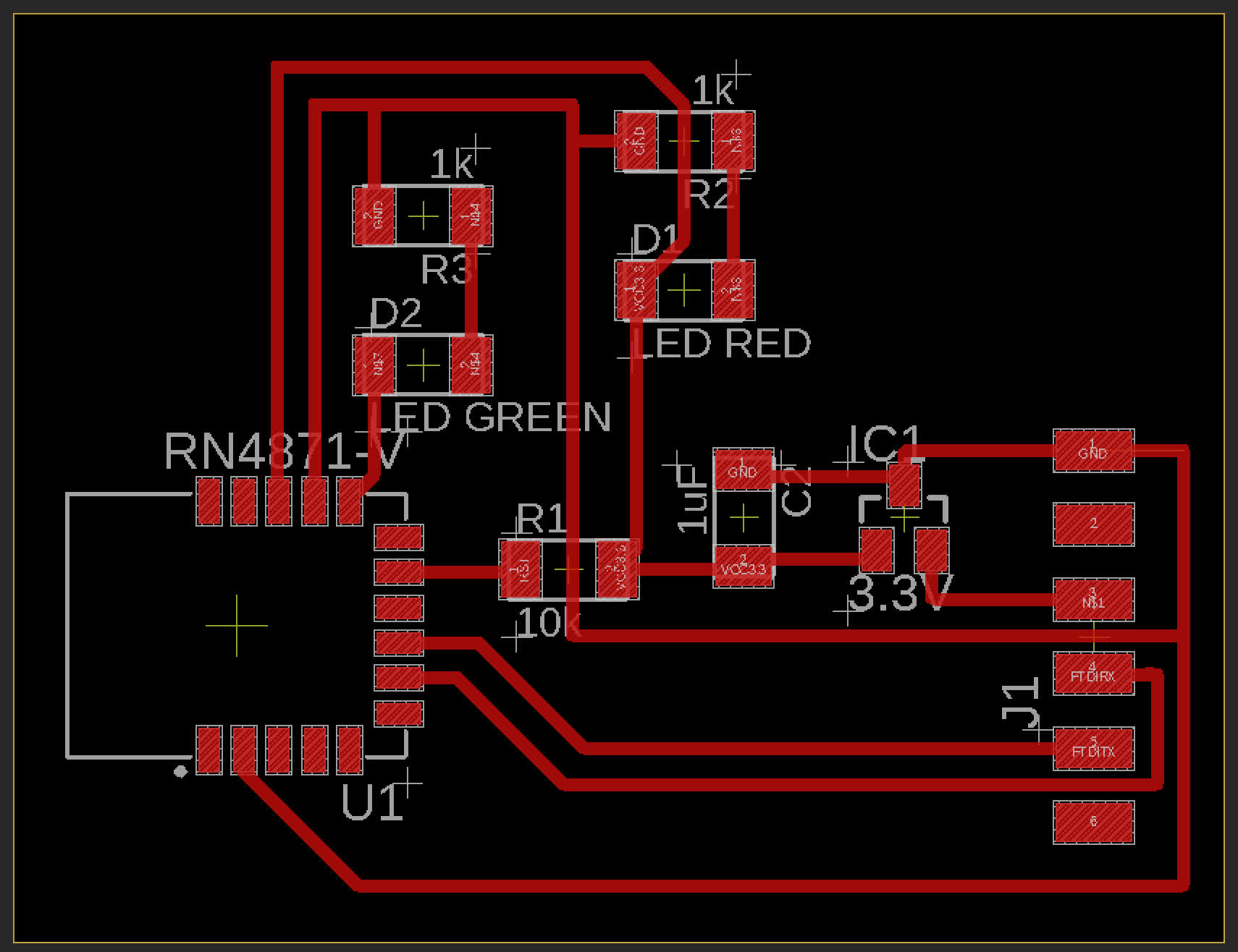
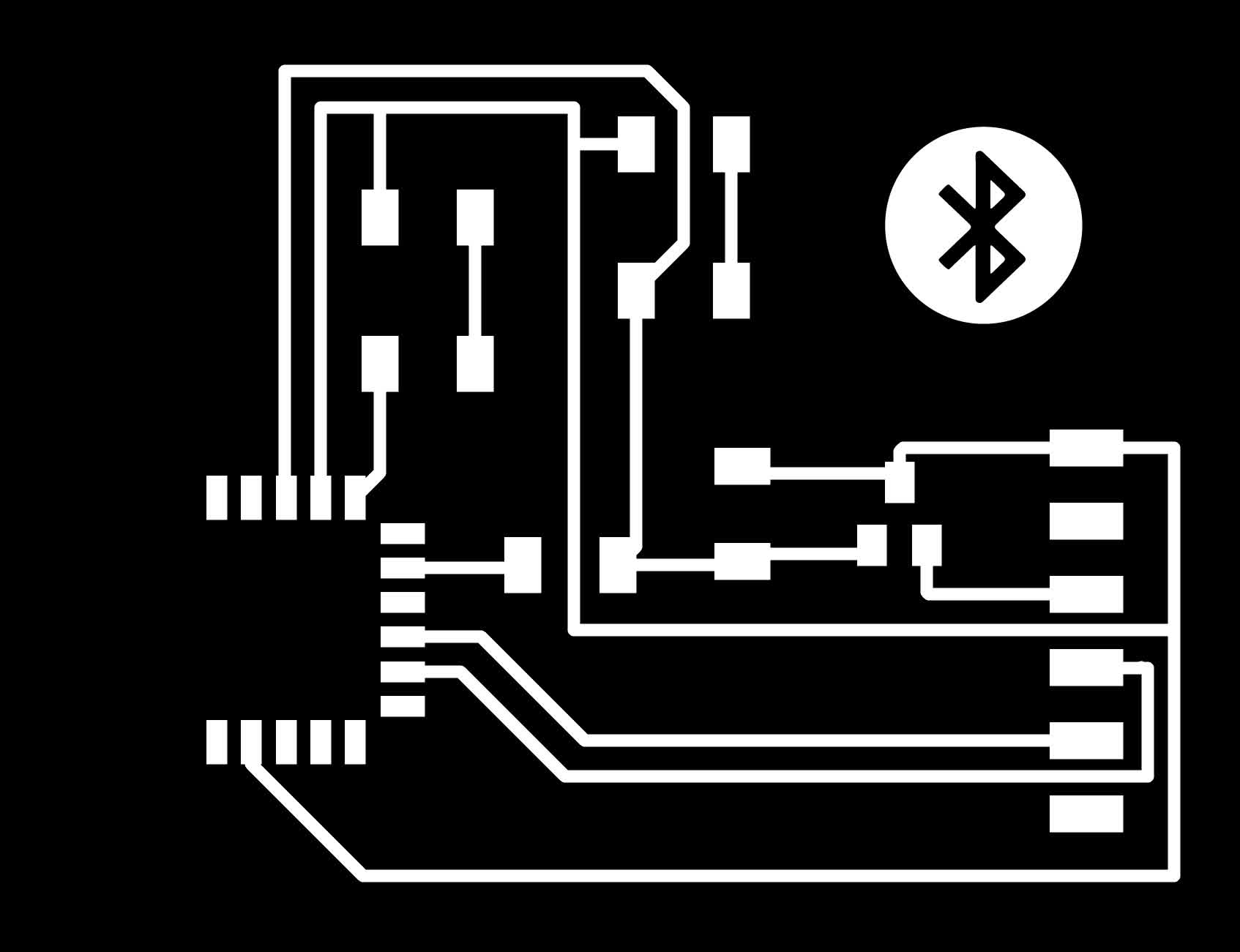
First, I designed a schematic, routed a board and exported traces. The design emulates the examples I referenced above.
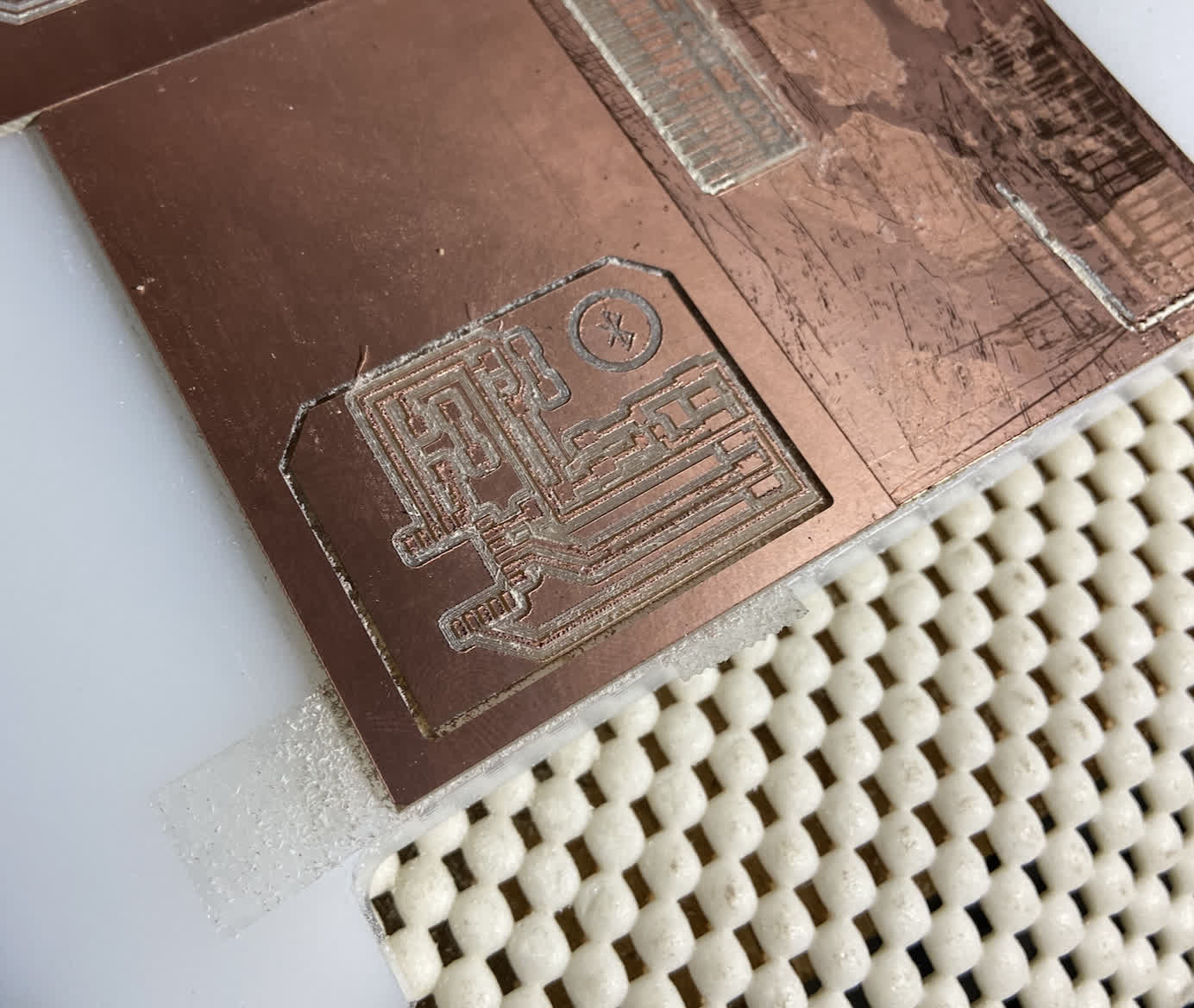
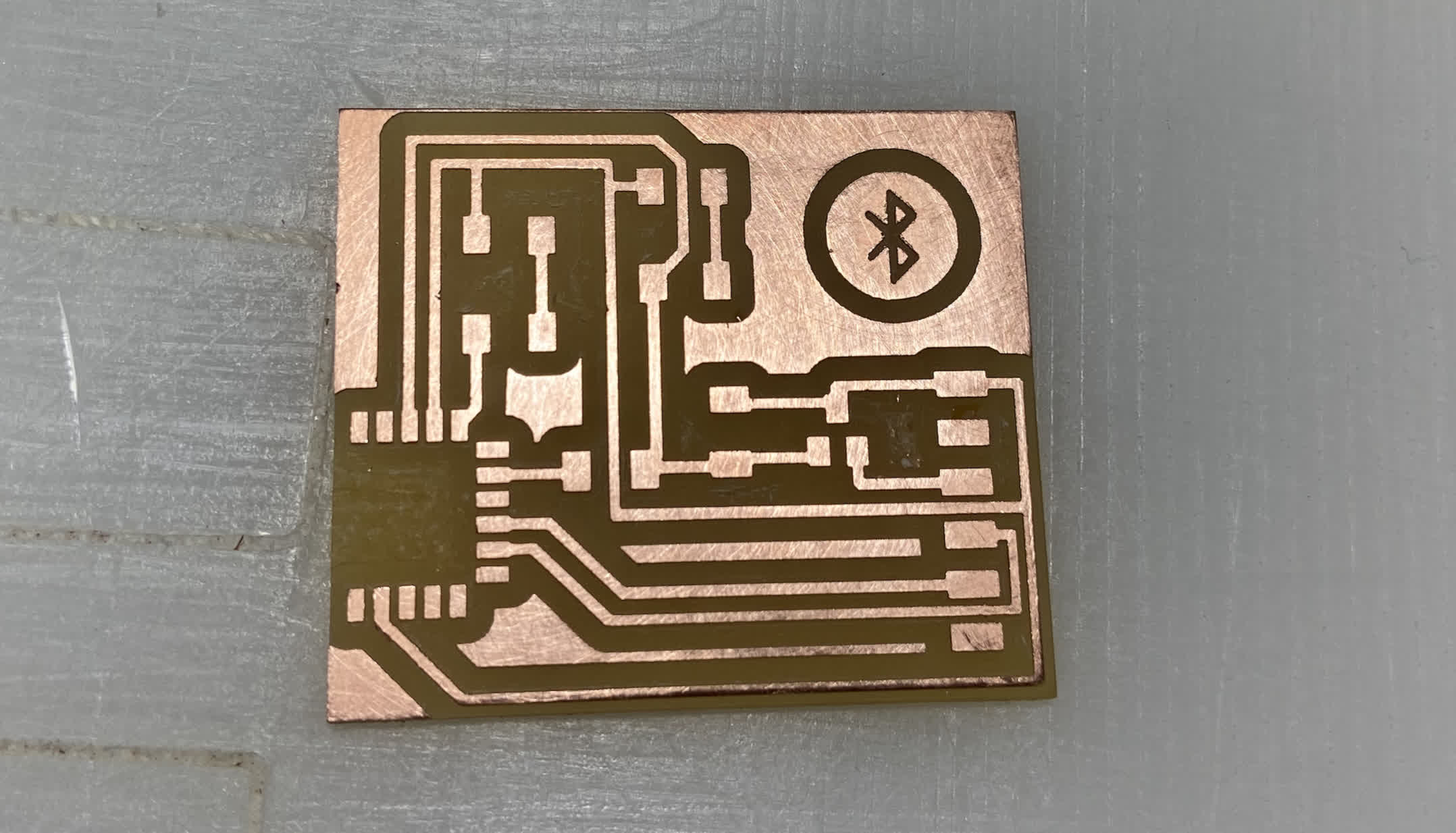
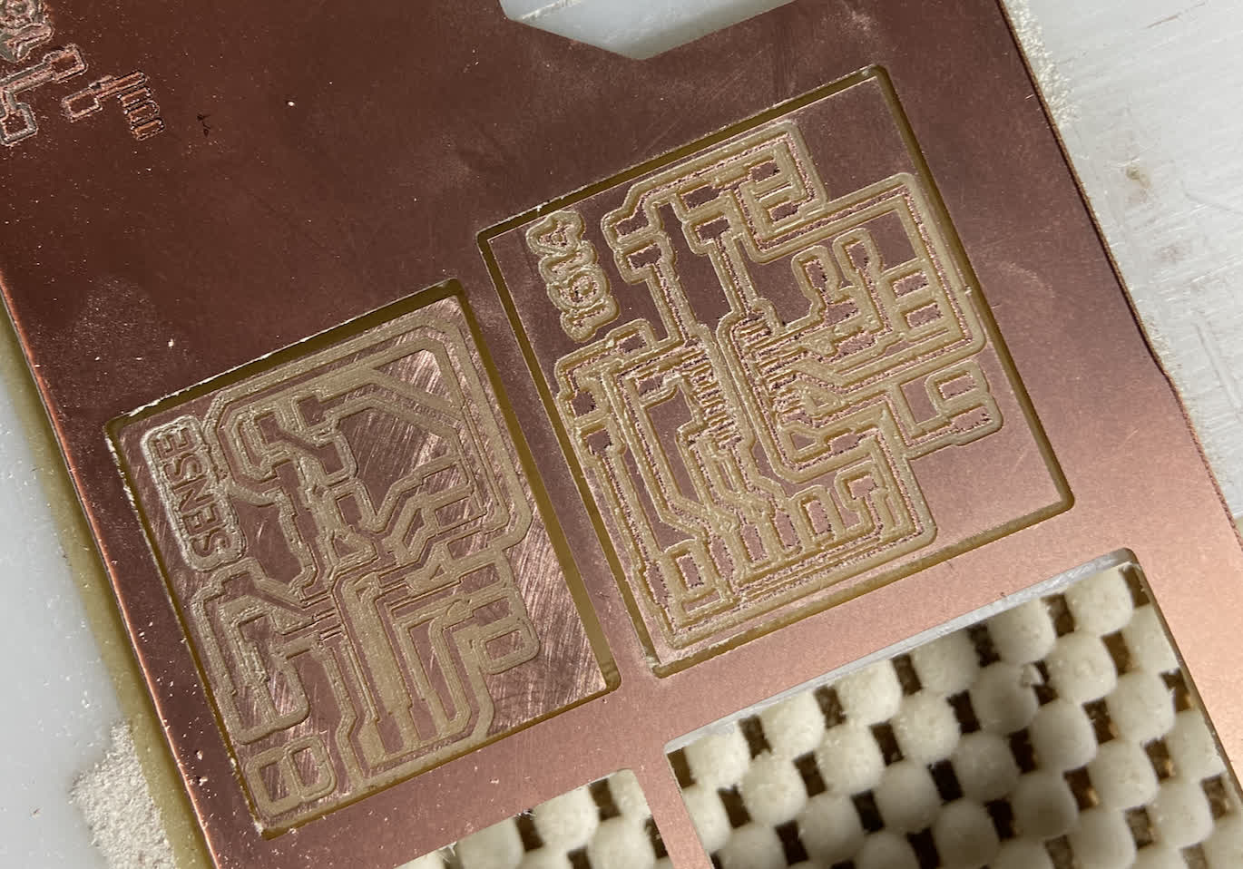
Bring it to Clank. Based on a recommendation from Anthony, I rewired my Clank to reverse the spindle rotation. This is what had been causing the poor quality of cuts with the end mills. They had been cutting in reverse, just pushing material instead of cutting it. I used an engraving bit for these traces, but the 1/32" bit cutout looks 100X better than the previous versions, which I think proves the theory.
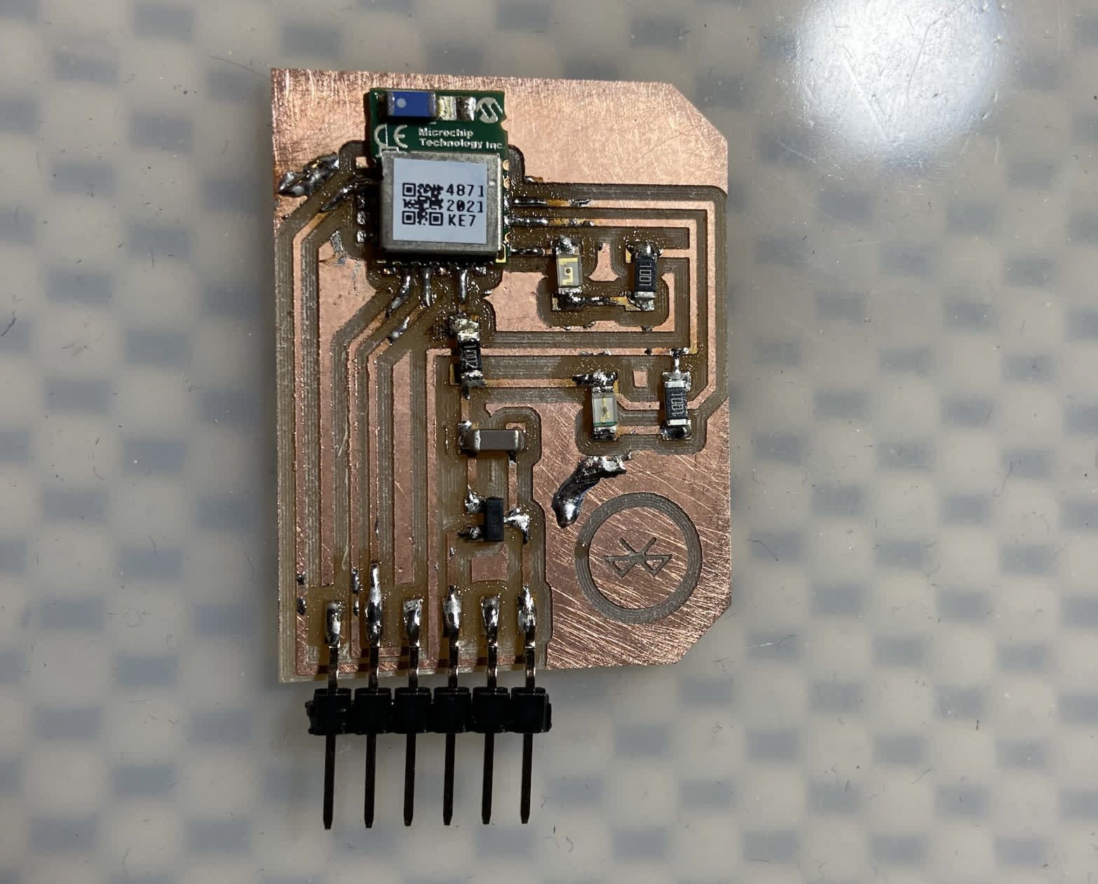
Soldering the RN4871 proved to be a bit of a bear. This first crack did not go particularly well.
Considering the low quality of my first soldering job, and that I wanted to test out the cutting quality of the 1/64" bit, I decided to mill another board using the 1/64" bit. The cut quality came out really nicely, but the trace width was much narrower than the result of the engraving bit.
I raised an issue about the differences, wanting to know if this was a hardware issue or software issue. Some theories circulated around the belt tightness and screw tightness. This might account for variabiltiy in trace width, but the widths were pretty consistent across both boards--just different. Anthony mentioned that thicker traces are to be expected from the engraving bit, as the width will depend on the depth of the cut--considering the shape of the bit. I thought that was a good idea, so I check the width with my micrometer. I designed the board to have a trace width of 16mil, and the first board--the one milled with the V-bit--was pretty much dead on 16mil while the 1/64" endmill's traces were sitting at about 10mil.
I did some surgery on Clank, tighted belts and screws, check the parts overall and ran another test. The same result came of the test. I now wonder if there is something going on with the software. Did I somehow set my toolpath to cut on the interior or midpoint of the line instead of the exterior? I haven't figured that out yet.
Testing: Round 1
I didn't have a lot of faith in this first board, but I had one RN4871 chip, so I didn't want to risk messing it up by removing it from the board with the heat gun.
To test the board, I again referenced Jim's networking week.
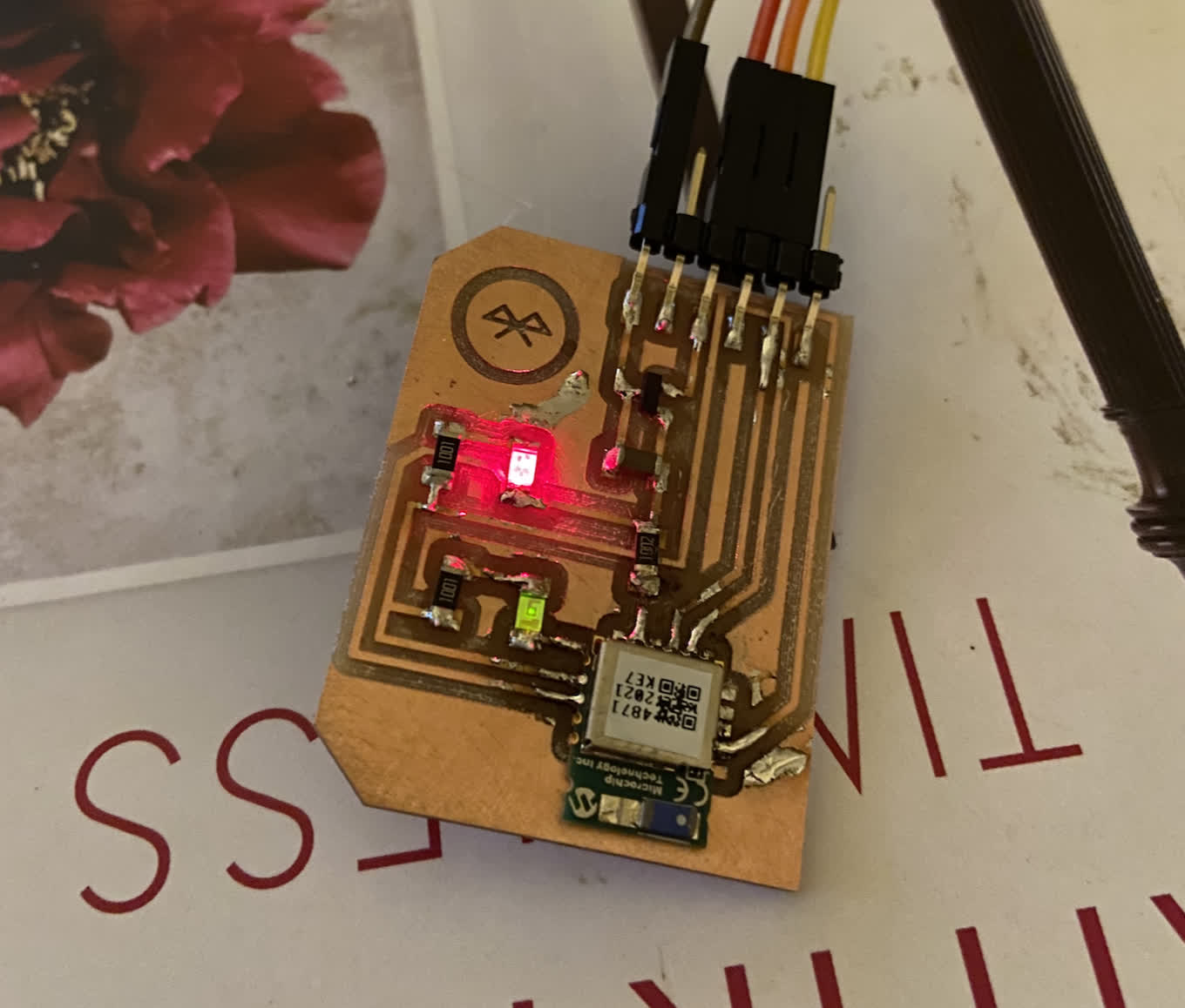
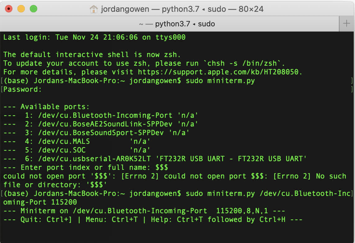
As you can see in the image above, the green LED is a little dull. I kept pushing forward with the workflow using miniterm, but I ran into a dead end in Terminal. miniterm a la Jim and Rodrigo's approach.
I thought it might be a continuity issue, but instead of checking that as the board sat, I assumed it was a problem of pins being connected beneath the body of the chip. So I ripped it up with the heatgun and mangled both the chip and the board. So I needed to order another chip online to try it again.
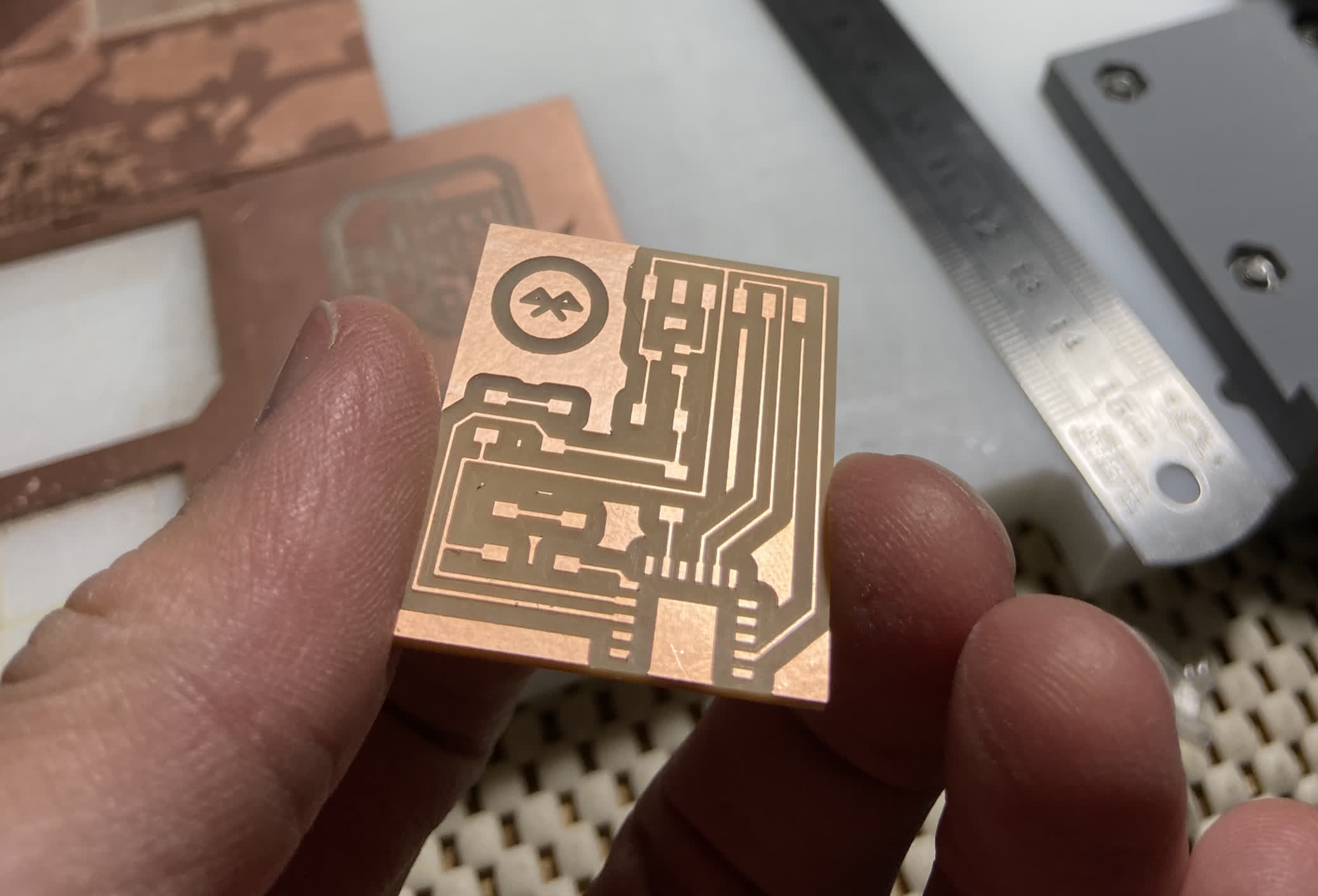
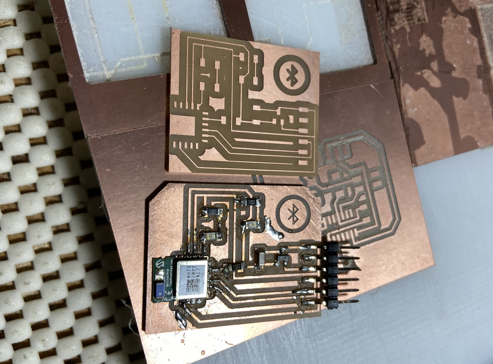
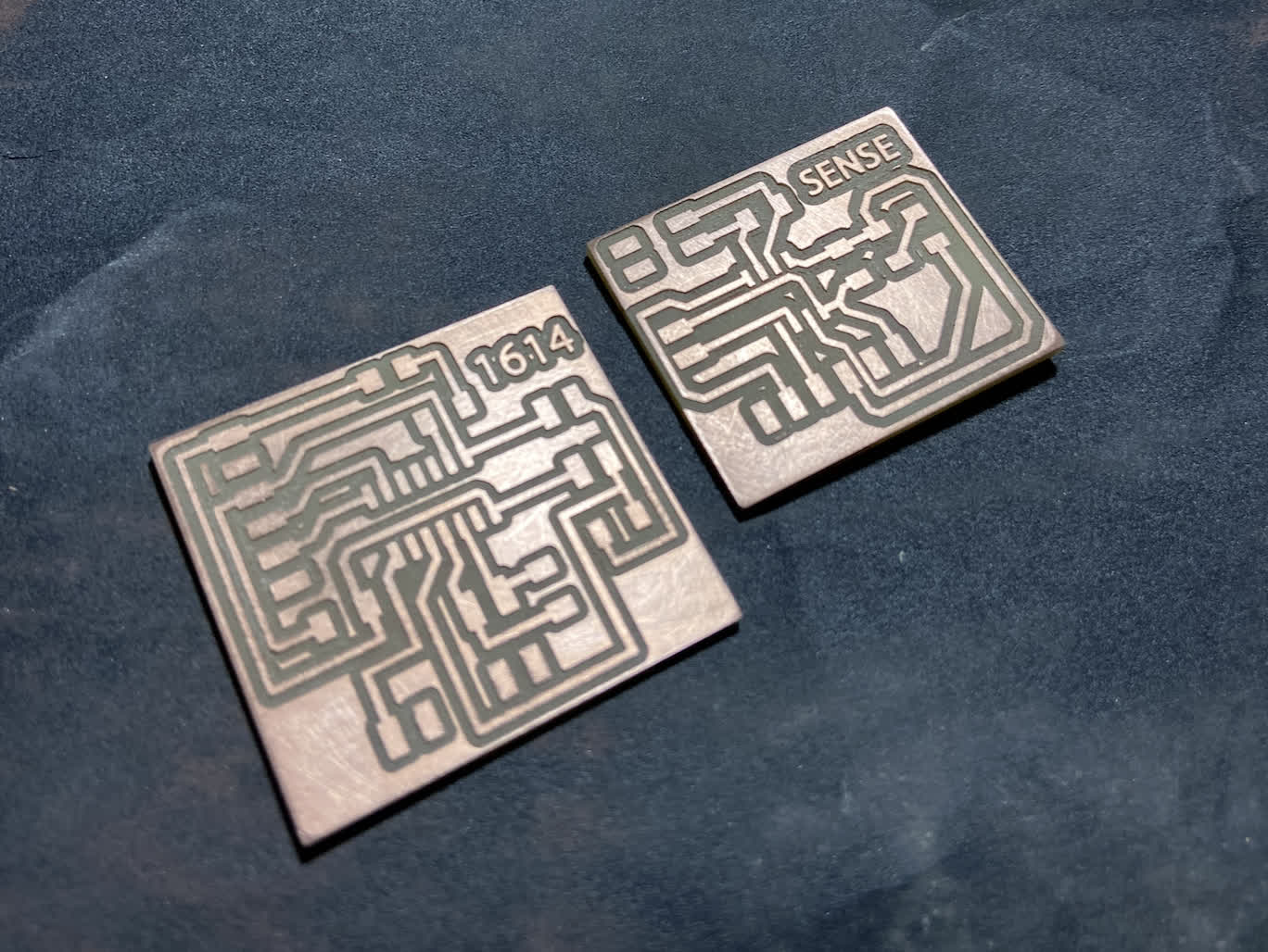
The thin trace board was a casualty of the first round of trying ot make the mangled RN chip work. So I had to make another. This time, I used the V-bit because its results have been more consistent trace width even if the cut quality is worse. See the resutl below:
Stuffed board looks a lot better too.
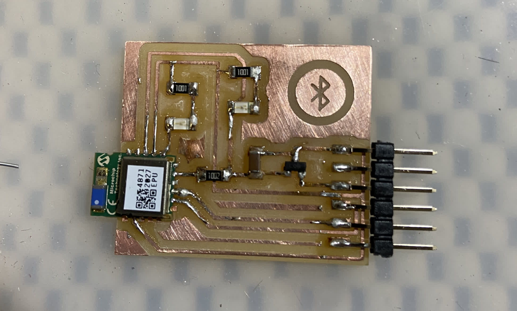
And yet, I get the same result in testing.
Files:
Bluetooth.sch
Bluetooth.brd`
Bluetooth_traces.png
Rerouting to Serial
I fell off a bit of a cliff this week. I bore into rabbit holes while trying to get my neopixel and ATtiny1614 board to work together, and I put most of my early efforts on this assignment into the bluetooth chip, which did not go well. So I decided I should start over, begin with the basics and just try to get some board to talk together via serial. I was hoping I'd be able to use existing board--being short on time both this week and in regard the final project itself--but I discovered that I hadn't connect pins to both RX and TX pins on either of my ATtiny boards. I didn't want to risk ruining working boards by doctoring the connections, so I designed a couple new boards.
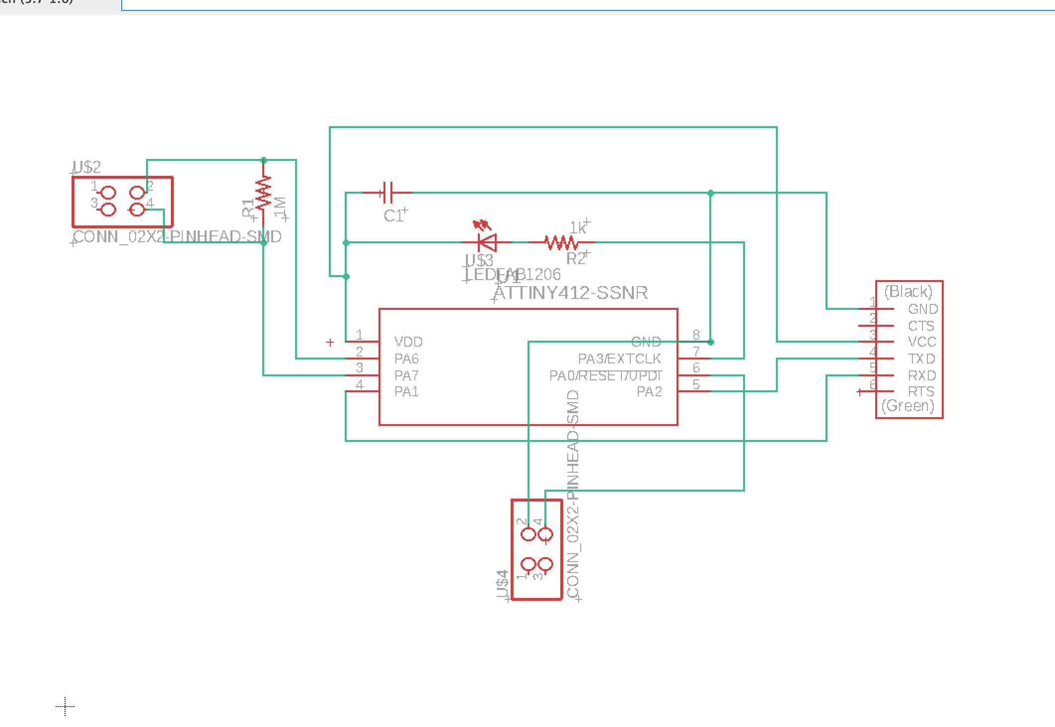
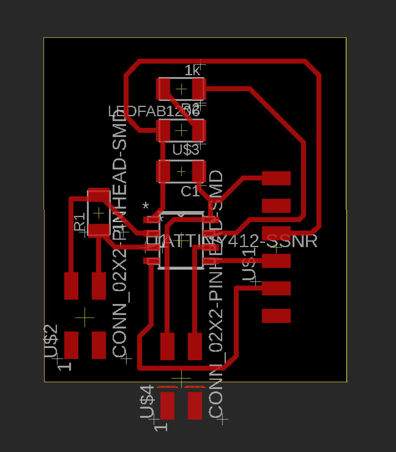
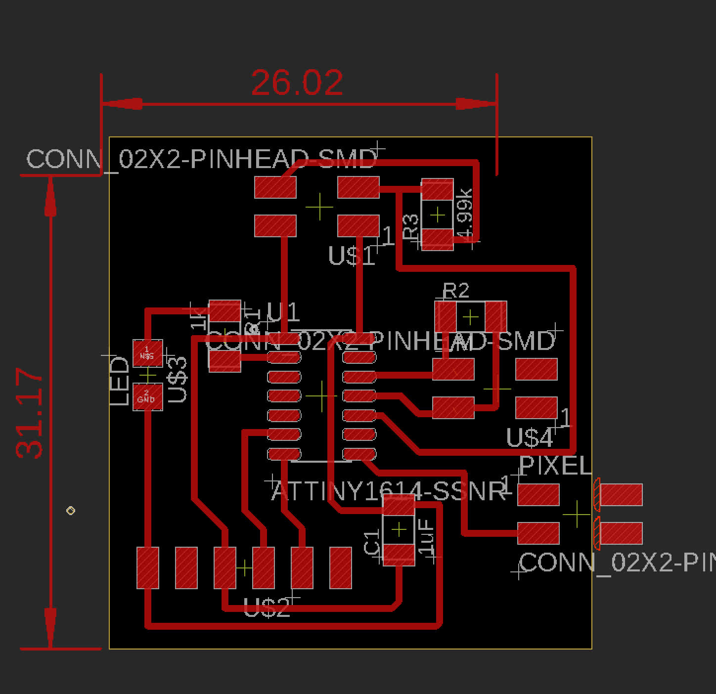
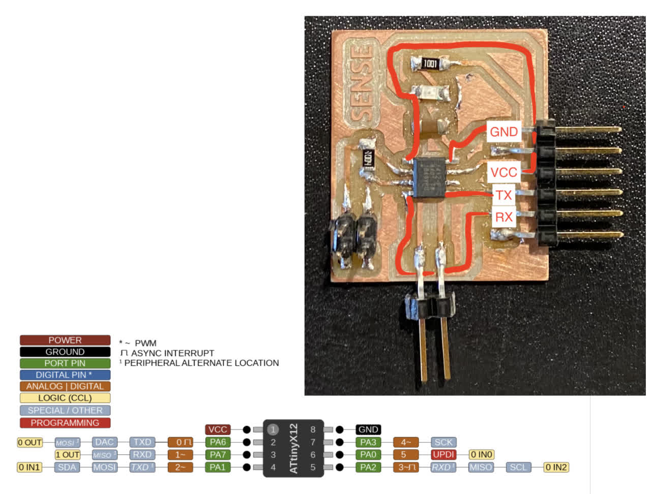
I have been wanting to work on a capacitive sensing input over the last few weeks, but I haven't had a chance quite yet. I decided this could be an opportunity to at least get a jump on that. Omar mentioned that Elaine Liu's project might be a helpful reference, and I think there is definitely a lot of overlap in the funtionality I'm trying to accomplish. So I took to copying her ATtiny412 input board as a starting point. Here is the schematic and board:
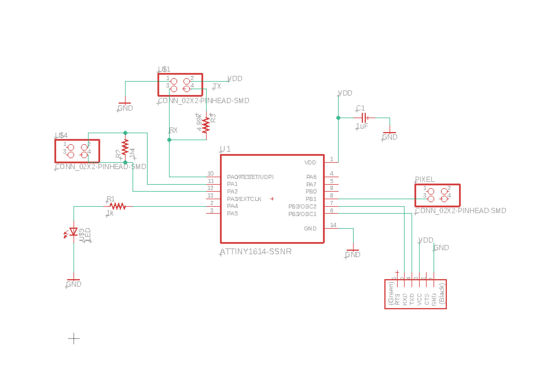
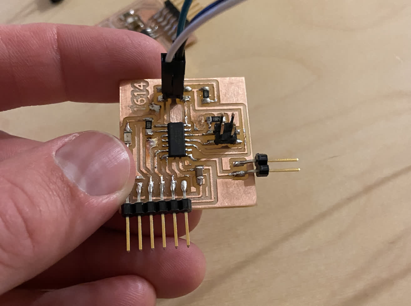
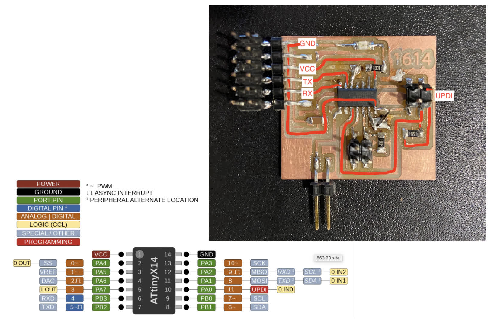
I wanted to use my Tiny1614 board from the output devices week because I've been spending so much time with that and the NeoPixels, but I found that it was lacking the RX/TX connections required to wire another board to it. I had UPDI TX and RX, but nothing attached the actual corresponding pins on the chip. So I unfortunately had to create that file as well. Here is the Schematic and Board:
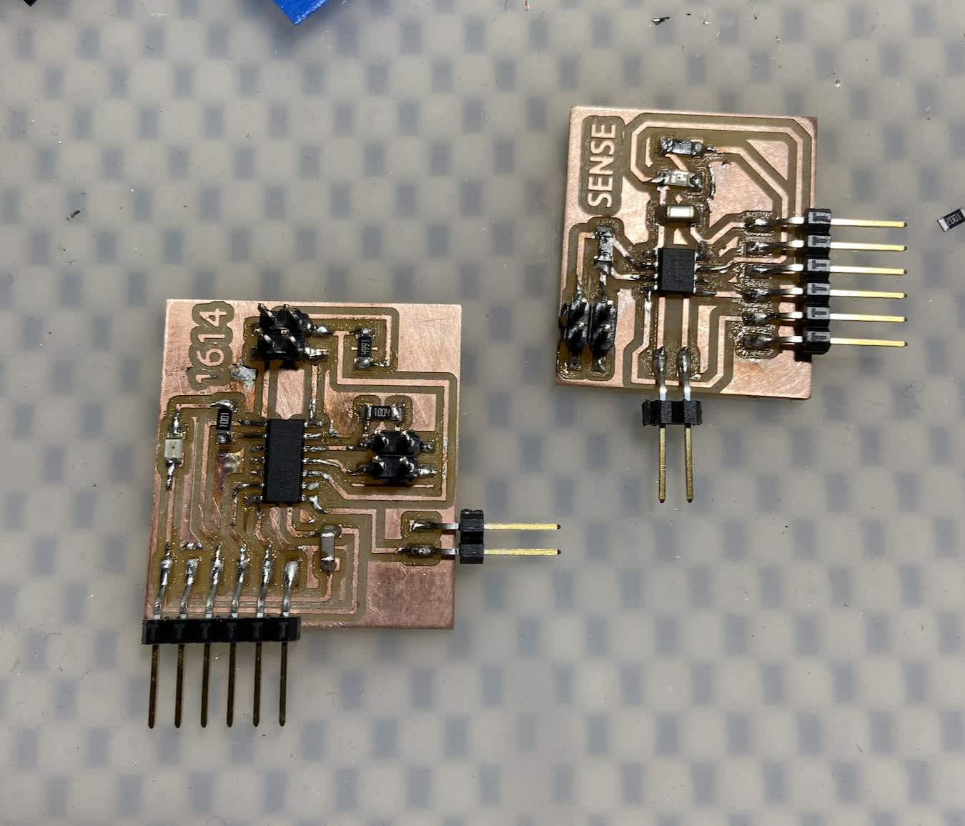
I've gotten pretty efficient with the Eagle to Clank to soldering workflow. I was able to complete two fully new boards in about 2.5 hours--down considerably from my starting point--and they both took an example Blink program well.
A fun result of the NeoPixel troubleshooting with Anthony is that my Arduino Nano is now converted into a UPDI programmer, so I realized I should able to upload a Blink example right from the IDE instead of following the arduous hex file process that is required of the FT232 in my current setup. So, with that in mind, I tried it out on the ATtiny412 board first. It worked!
I then ran the same process on the new 1614 board. Unfortunately the board's LED got cooked as I was soldering so I couldn't see if the programming had actually worked.
I quickly switched out the light and connected power and ground, and the light started blinking. So I've got two blinking boards.
So, now that I had working boards, it was time to pause and figure out whether I could get them to talk. I think I should have figured that out first... Seems to be a trend. Anyway, I took to referencing Elaine's page again, and I also found the group project from Xinhui Hu to be informative.
I knew that I would need to connect both boards to the same Ground and Power, and because I didn't use a 3x3 pin header on either board, I thought I might be able to use the example of a Rx/Tx hub as a way to hook up my boards:
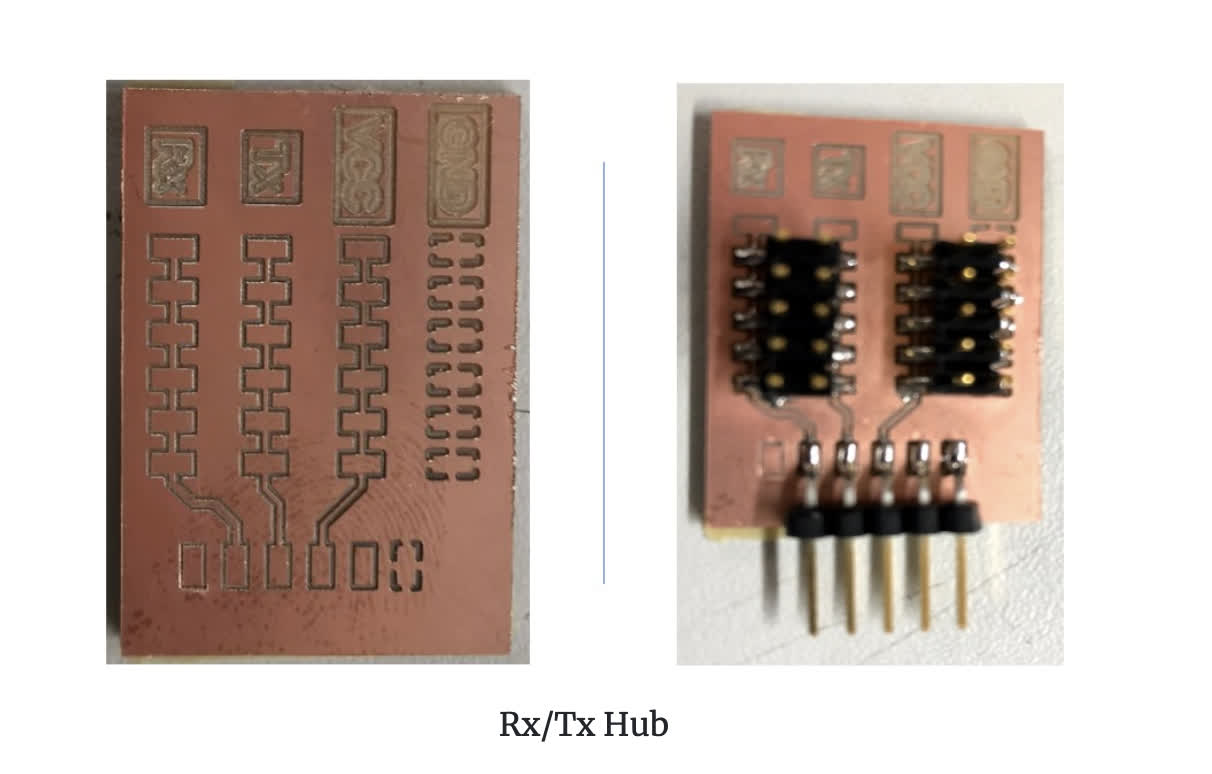
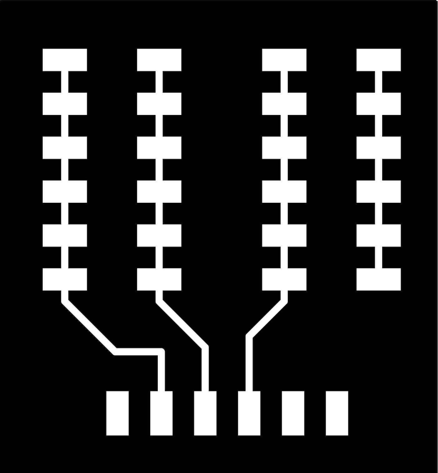
I designed my own in Eagle, but I didn't have time to mill it. It's pretty much exactly the same as the example board:
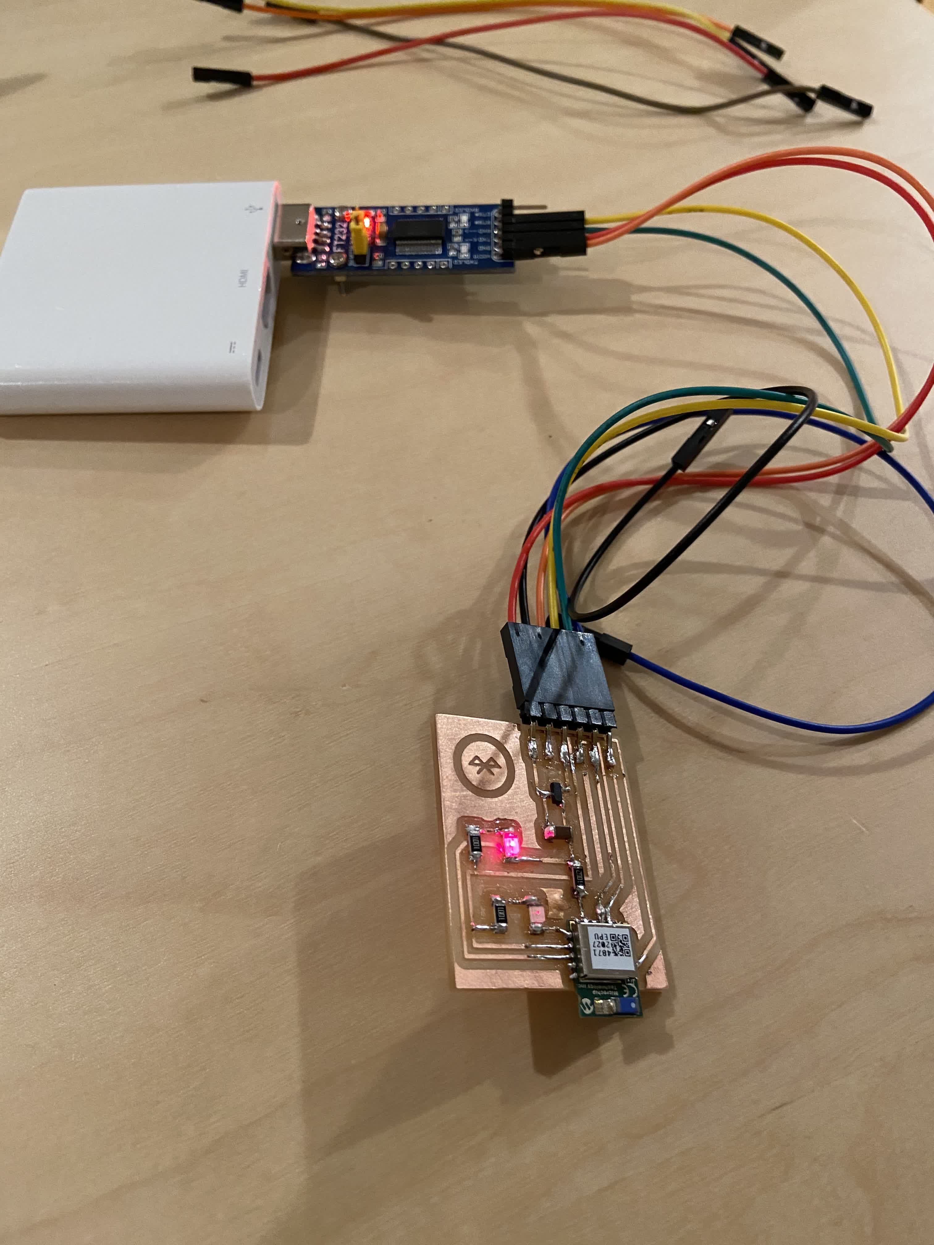
In the interest of time, I wired up my breadboard to function at the hub:
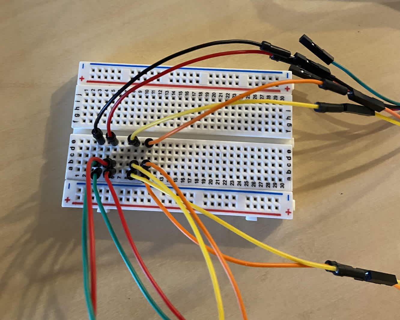
And this is where I got stuck again. I have boards connected to the same source, but I am unsure of the next steps. Because I blended two examples, I could't follow either path exactly, so I needed to do a little digging to figure whether this setup could work as is. I know the boards work, but the question remains as to whether I need to program them separately or if I could program another board to speak to these nodes.
After reviewing my schematics, I realized that I should be using the 1614 as my Master Board, and I am still lacking dedicated Rx/Tx pins for software communication to the 412 node board. So before getting these things to communicate with each other, I need to plug into these pins.
Files:
412_traces.png
412_interior.png
1614_sensor_traces.png
1614_sensor_interior.png
Connecting Rx & Tx, Getting the Programming right:
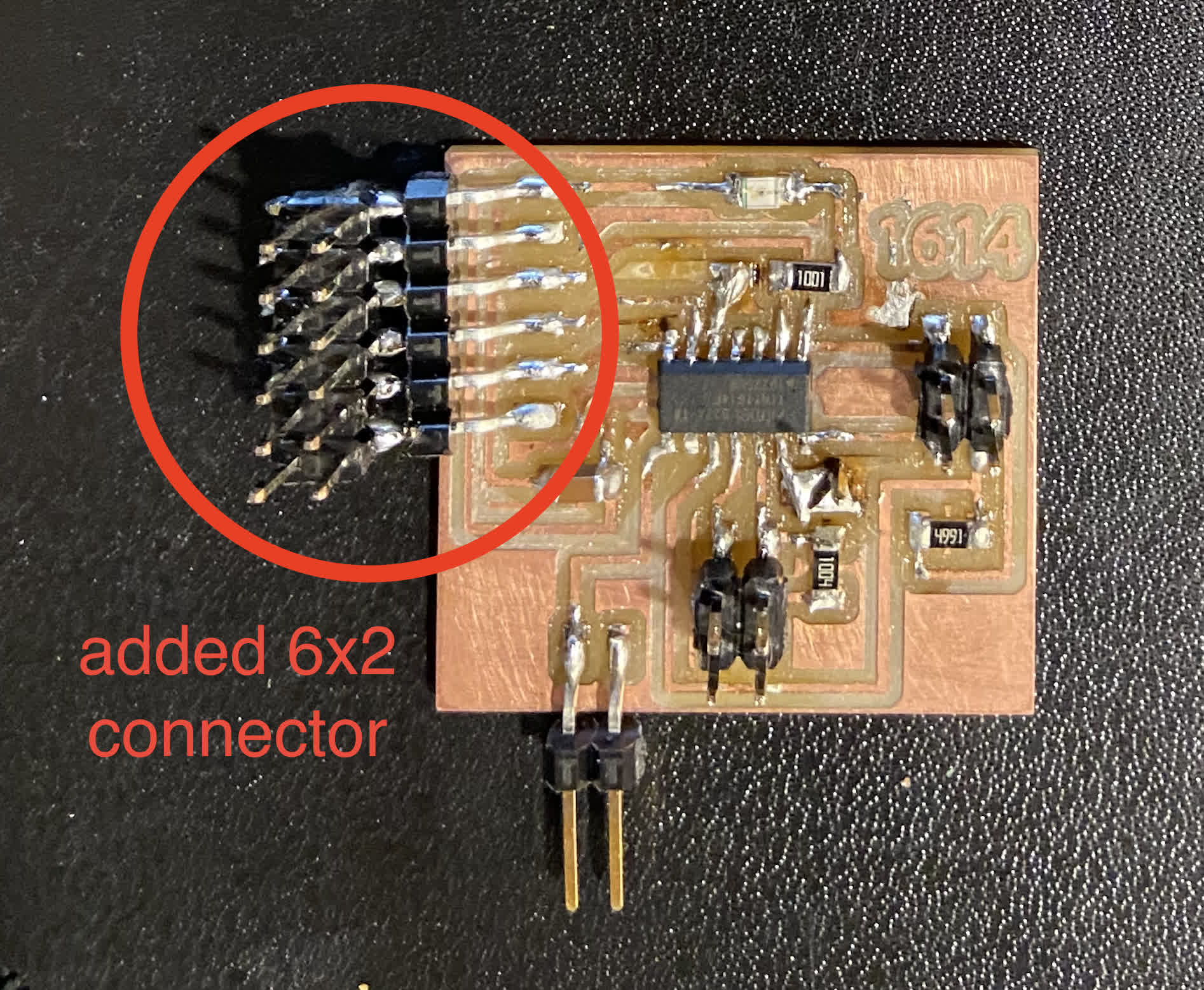
I scrapped the idea of the hub after seeing some examples reviewed in class. I also spoke a little more with Omar who communicated a little more clearly the difference between designating SoftwareRx/Tx and routing a connection with the actual Rx/Tx pins on the chip. I needed to break out two more pins to create those software Rx/Tx connections on my 1614. Basically, I am pretty sure I would need to break out two more pins on the 1614 if I wanted to create a software connection to speak to the 412 board. I haven't had great luck with that kind of direct pin soldering surgery so far, but luckily, in class I saw Cody's really clever solution to creating more pin connections, so I decided to give it a shot!
Basically, just add a 6x2 pin header to the ftdi pin header, and you've got double the connection points:
Now, I needed to take another step back and review my connections and understand whether I could connect the two boards I have with the existing layout.
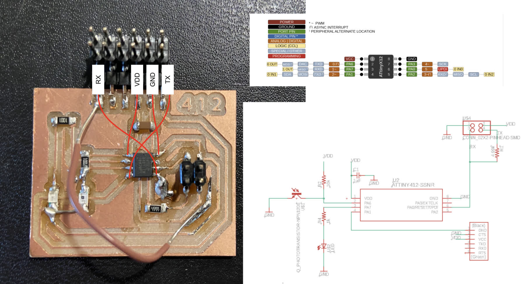
Here is the 412 board as connected prior to adding anything (added chart for reference):
Now for the 1614. No additional connections to the chip pins, but I have soldered the 6x2 pinheader to the 6 pin connector at this point and created wire bridges between two additional pins and some floating vestigial copper pads:
Now the major question is whether this 1614 can be connected to this 412 board. I still don't fully know if it can, but considering I have pins connected to the Rx and Tx of the 412, I should be able to wire those and the ground and power to the 1614 board. I think the bigger question is whether I need to hook up these separate pins on the 1614 to act as software serial connections or if the addition connections to the Rx and Tx pins that are available on my tacked on pin header will suffice.
For good measure, I brought out the other 412 board I fabricated for the input device week--mostly because I got the photo sensor working, and I haven't yet figured out the capacitive sensing bit. Here is that board:
Programming: Serial Testing Round 1
This was a tough process for me. I am still struggling to understand both how the boards connect and how the code needs to be written to allow multiple boards to communicate. Considering that discomfort with the process, I wanted to start by referencing another project that used the same boards as me. Cody's code seemed simple enough so I started there:
              int ledPin = 0;
              int rxPin = 3;
              int txPin = 2;
              int incomingByte = 2;

              void setup() {
                // put your setup code here, to run once:
                #define node_id '0' // change this code
                pinMode(ledPin, OUTPUT);
                pinMode(txPin, INPUT);
                Serial.swap(1);
                Serial.begin(115200);
              }

              void loop() {
                // put your main code her, to run repeatedly:
                if (Serial.available() > 0) {
                  //read the incoming byte:
                  incomingByte = Serial.read();
                }
                // say what you got:
                if (incomingByte == node_id) {
                  digitalWrite(ledPin, HIGH);
                  pinMode(txPin, OUTPUT);
                  digitalWrite(txPin, HIGH);
                  Serial.print("node");
                  Serial.println(node_id);
                  delay(1000);
                  digitalWrite(ledPin, LOW);
                  pinMode(txPin, INPUT);
                }

              }
I used this code to program both the 1614 board and the 412 boards--making sure to change the node ID for each--and tested each independently in the serial monitor. I got responses from each of the programmed 412 boards, but not the 1614. I'll need to check the code and connections on that board, but I wanted to see if the 412 boards could communicate via serial before troubleshooting that third board.
Testing Node0: 412 photosensor board
Testing Node1 and Node0 Connection:
So both the boards communicate independently, but when I hook them up, I can only receive a "node" test response from one. I tried reversing node1 and node 2 in the chain, and I got a "node0" response and "node1" gets a blink from the LED on the node0 board.
Node0 serial monitor response:
Node 1 blink:
I tried reprogramming the boards, checking the connections between Rx and Tx, switching which is designated node1 and which is node0, but I got the same repsonse. I think I'm going to try taking the SoftwareSerial route with the 1614.
I figured out the issue with the 1614 board--or at least a workaround with the existing code. I changed the clock speed from 20MHz to 16MHz and tested the communication. I got a response:
Success with two 412 boards:
As I was struggling to get my existing boards to work with each other, I decided to make some of the same simple bridge boards that Cody milled, mostly just to prove that I could get something to work. After milling and stuffing the two simple 412 boards, ran the arduino code on each, designating one with a "node0" ID and one with "node1."
One of the boards worked fine--received the program fine and returned the expected nodeID response in the serial monitor. On the other, I was getting weird responses when plugging in ground and power, and I realized after further inspection that I had bridged the ground and VDD wires with my soldering. I fixed that issue and ran the code again. The program supposedly uploaded successfully, and it does seem to receive input from my computer, but it does not send a response back. Because it is the same exact board as the "Node1" board, and the only difference is my added pinheader connection, I think there is probably something going on with the physical connection on teh Tx line. As you can see below, I get full two way communication from "node1" and I only get a lit LED and no "node0" response from the node0 board.
Because I thought was a hardware issue and not a software issue, I decided to try reprogramming one of my 412 boards that has successfully run two way communication in the past. I wired up the new 412 bridge board and my older 412 input board from week8, and the commmunication worked! We've finally got working nodes!
My working theory here is that I am setting something up wrong in the tools when I trying to communication between two different microprocessors. In the case of the 1614 to 412 connection, I have set a clock speed of 16MHz and 20MHz respectively. The baud rate is the same, and each does seem to communicate separately but not when they are connected. So something has to be off with how they are communicating between each other, and the different clock speed is the setting that I have noticed. I don't really have the reasoning to back that up, but it's a hypothesis. I'll keep banging my head against the wall until I figure it out, but for now, I've got some boards performing serial communication, and I'll take the win.