[10 Networking + Communications]
So far we've learned all sorts of ways to use microcontrollers on a board, whether it's with input or output devices or having it be able to talk to your computer. But what if you need multiple microcontrollers? What if you need to have different microcontrollers talk to each other and be able to take turns communicating with your computer? That's networking and communication! No, not drinks at the local making new work buds and working on your small talk skills. This week we needed to design, build and connect a wired or wireless node network or bus address. Then we needed to send a message betwen two projects. This whole concept was very new for me so I didn't want to aim too big and end up not managing it... so for me it was the simple multi-node serial bus.
Building a bus
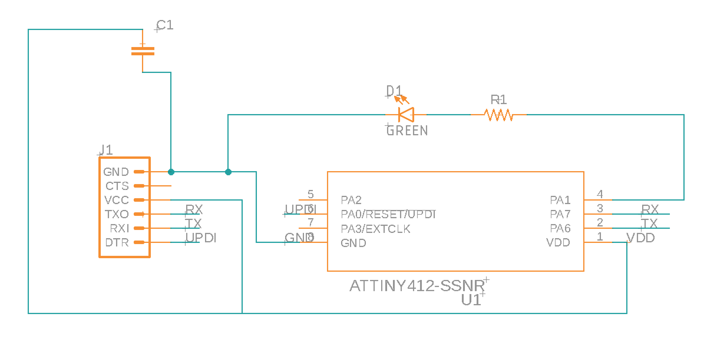
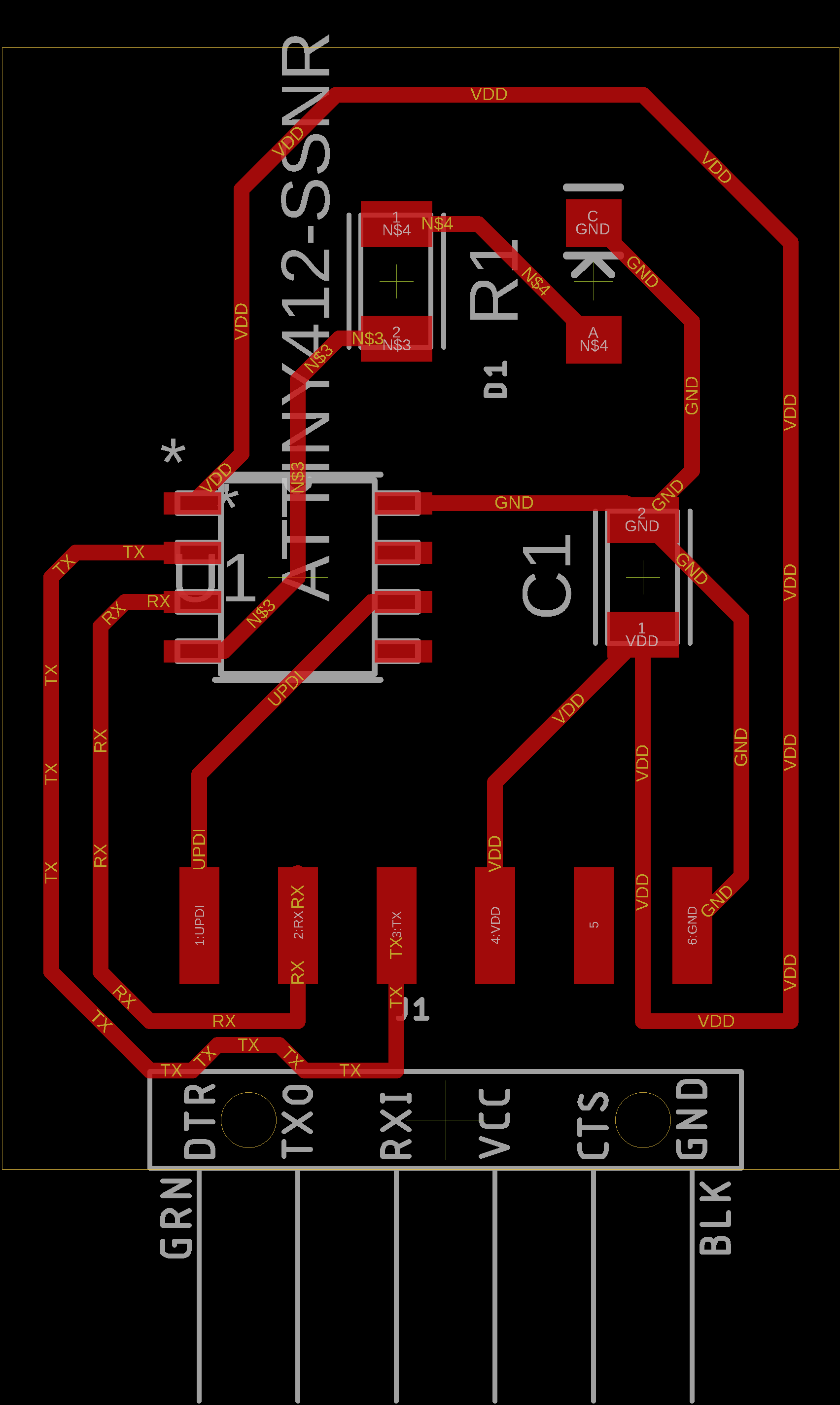
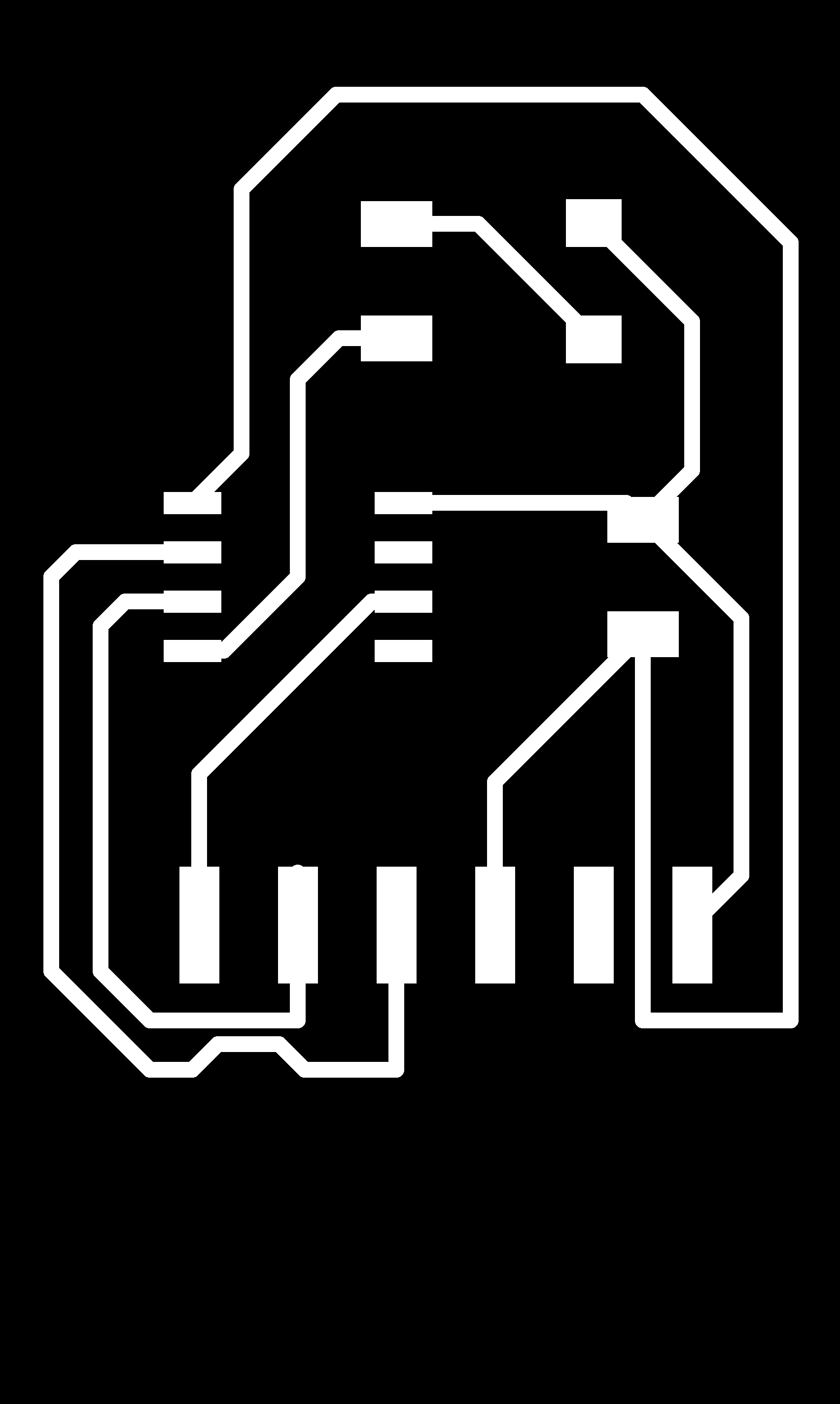
I designed a modular Attiny412 asynchronous serial bus board. I designed the board so that I could make multiples of the same board and have them all still able to work the way I wanted them to. Here is the board I designed:
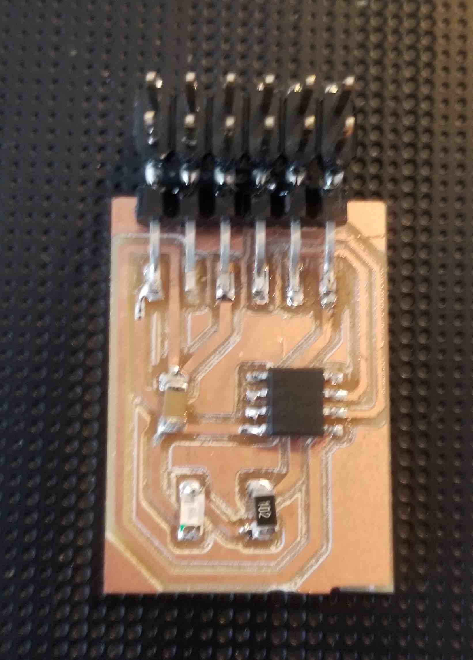
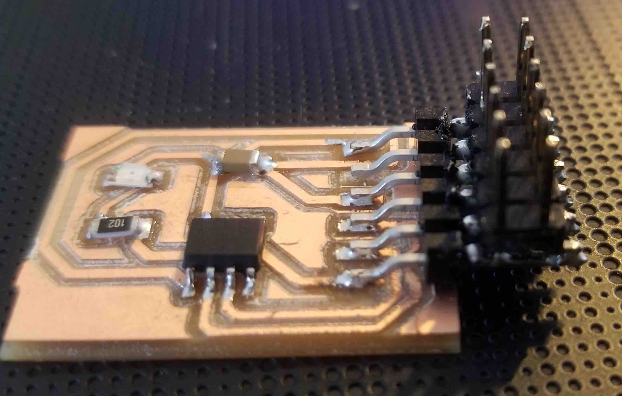
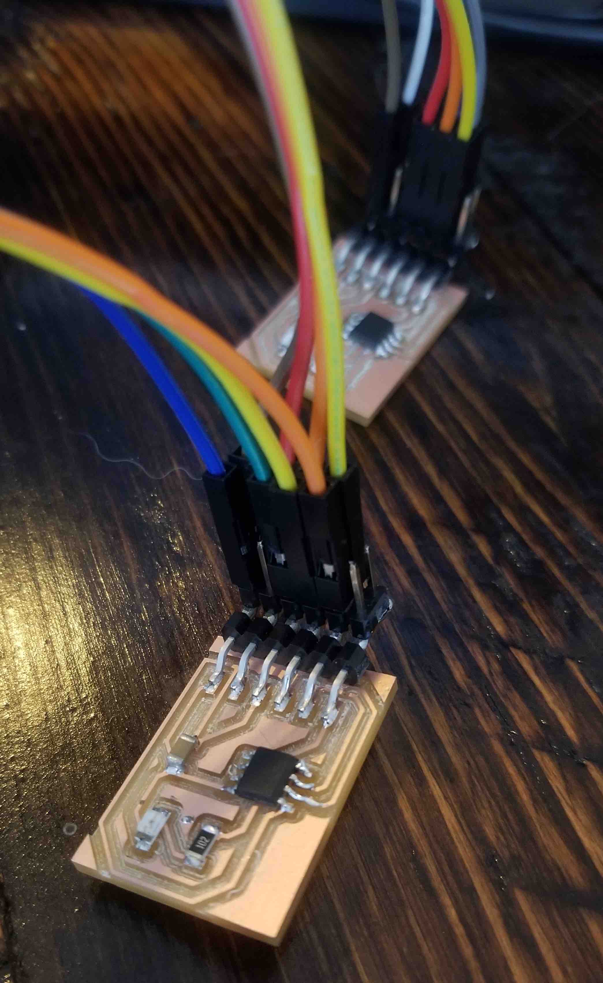
Since this was a pretty simple board, stuffing it was easy! I made three of them. One complication that I ran into, however, was that I made the board with the righ inputs, but I forgot that I would also need to have outputs for each of those pins as well! Initially I tried to just manually wire a little piece of wire between the connector pins. This was tedious and didn't work very consistently when I got to programming. Rather than have to reprint and restuff all the boards, I got creative and soldered some extra pins onto the existing ones. Here's the stuffed board and my fancy pin fix!
And finally, here's how the wiring works between the boards:
Programming the Network
The programming was complicated for me. Not really from the actual language perspective, but more so from a conceptual perspective. The key point that I learned from programming this bus was how to allow the boards to be constantly listening for their id to know when to light up their LEDs, but also to be able to take turns talking back to the computer. In particular, the transmit pin (Tx) needs to be disconnected when not transmitting, otherwise, even in a 'LOW' state they will fight with each other for control of the transmit line. To do this you need to set the Tx pin as an INPUT, setting it to a tri-state or 'disconnected' state. Then, if it recieves its own ID on the Rx line, only then, do you set the Tx pin as an OUTPUT, send the message that it got its id, and then reset it to INPUT again. Here is my final code:
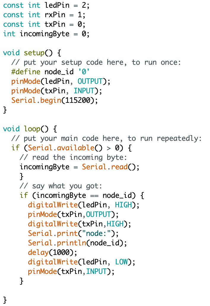
Note here that I've shown the code for only one of the nodes. I needed to create a code for each node changing the ID for each one. I programmed each board individually with it's ID, then connected them up to see how she ran! After a bunch of trial and error (and help!) I managed to get the boards working and communicating!
The Source Code