Week 10: Final Project Progress and Output Devices
Output Devices Assignment: Add an output device to a board you've designed, and program it to do something
I am making an LED lamp (or lamps), and I'd like it to respond dynamically, in brightness and in color, to a capacitive sensor and/or phototransistor. So I wanted to use a product that is already built to perform those functions. The Adafruit NeoPixel Rings seemed like a good option. I thought it would be a pretty simple addition because I really just needed a single DC pin to program the Ring and a ground and power connection. Alas, it's never that simple.
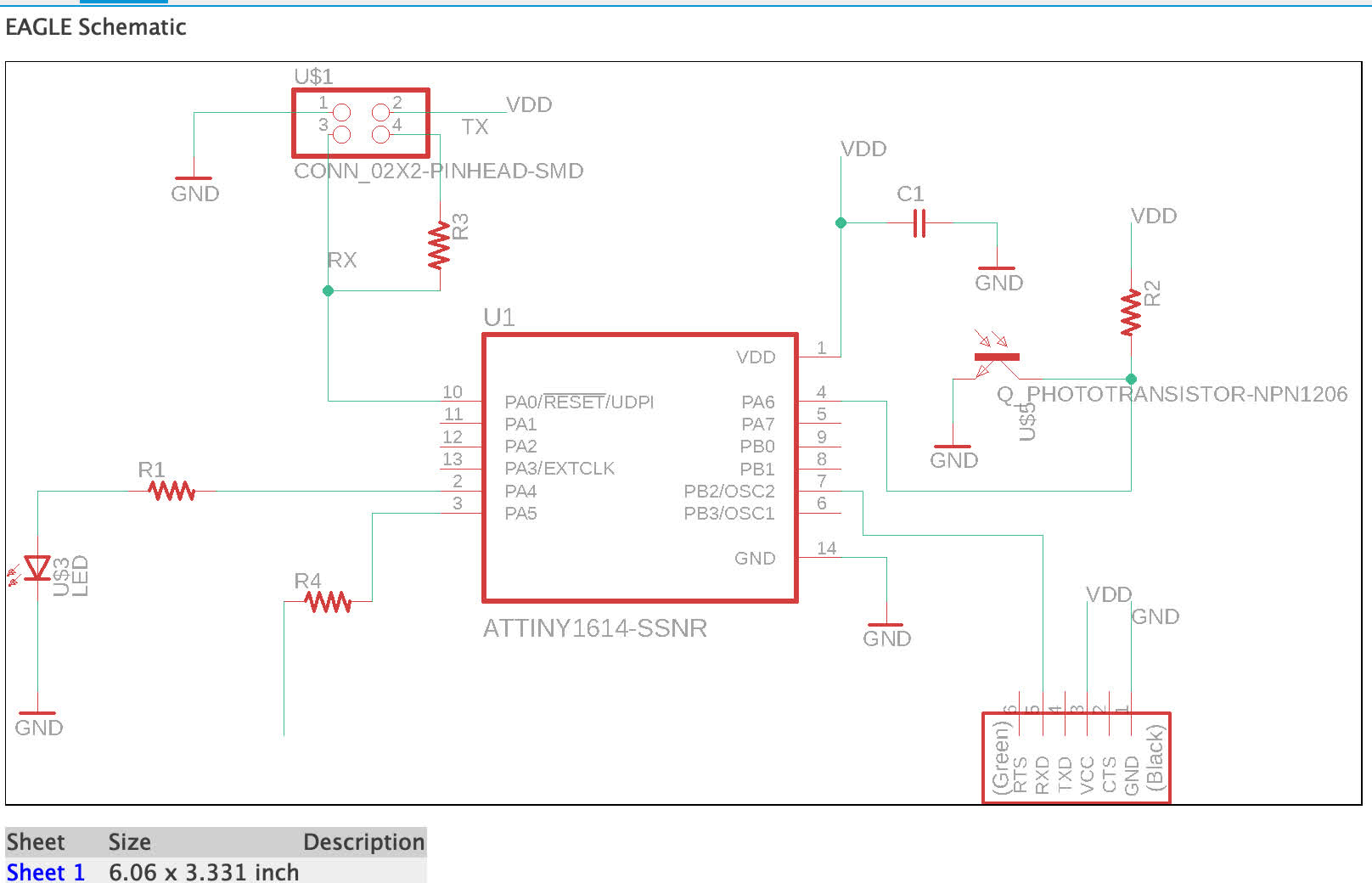
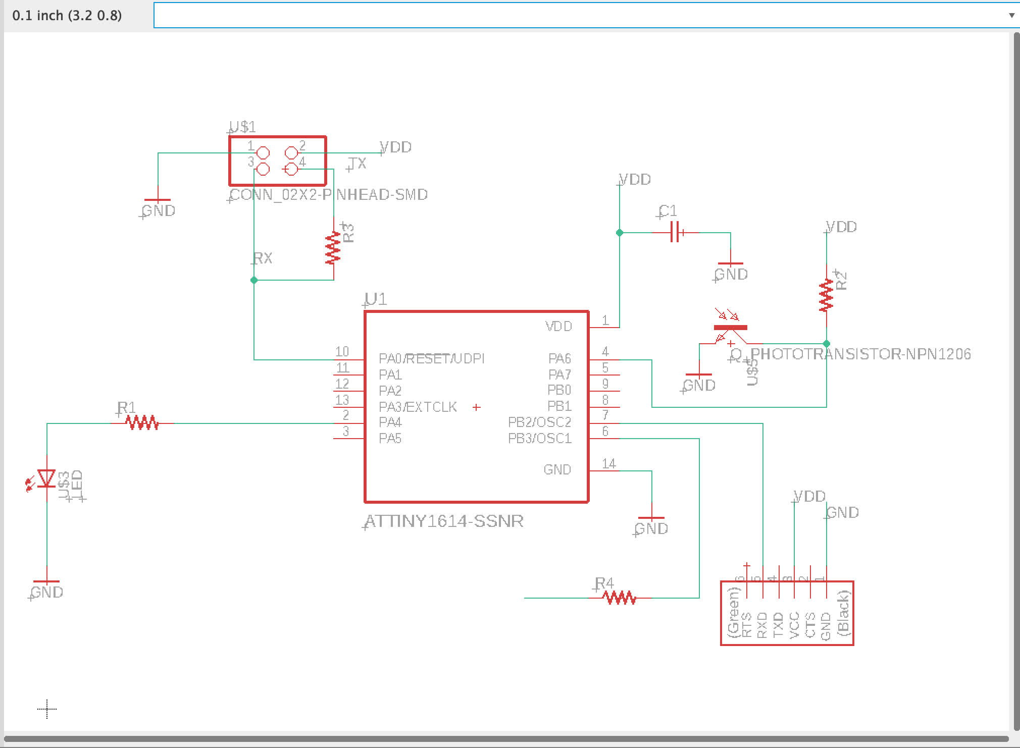
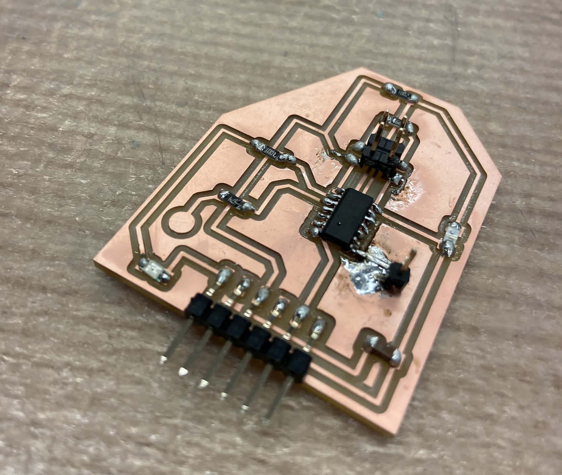
I had an ATtiny1614 queued up in Eagle for this week, so I added a wire to a PA5 (which is Digital/Analog according to my handy chart).
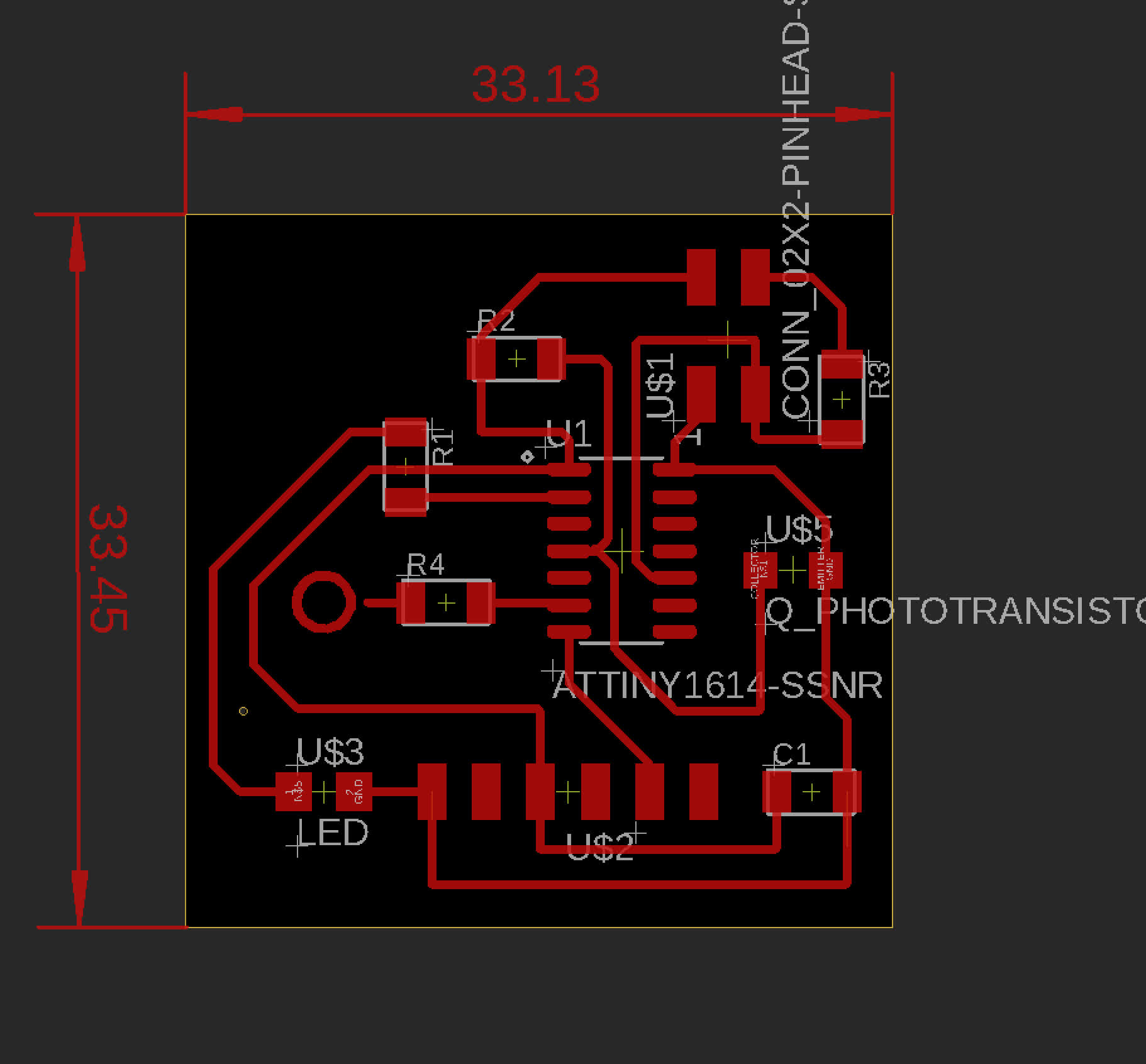
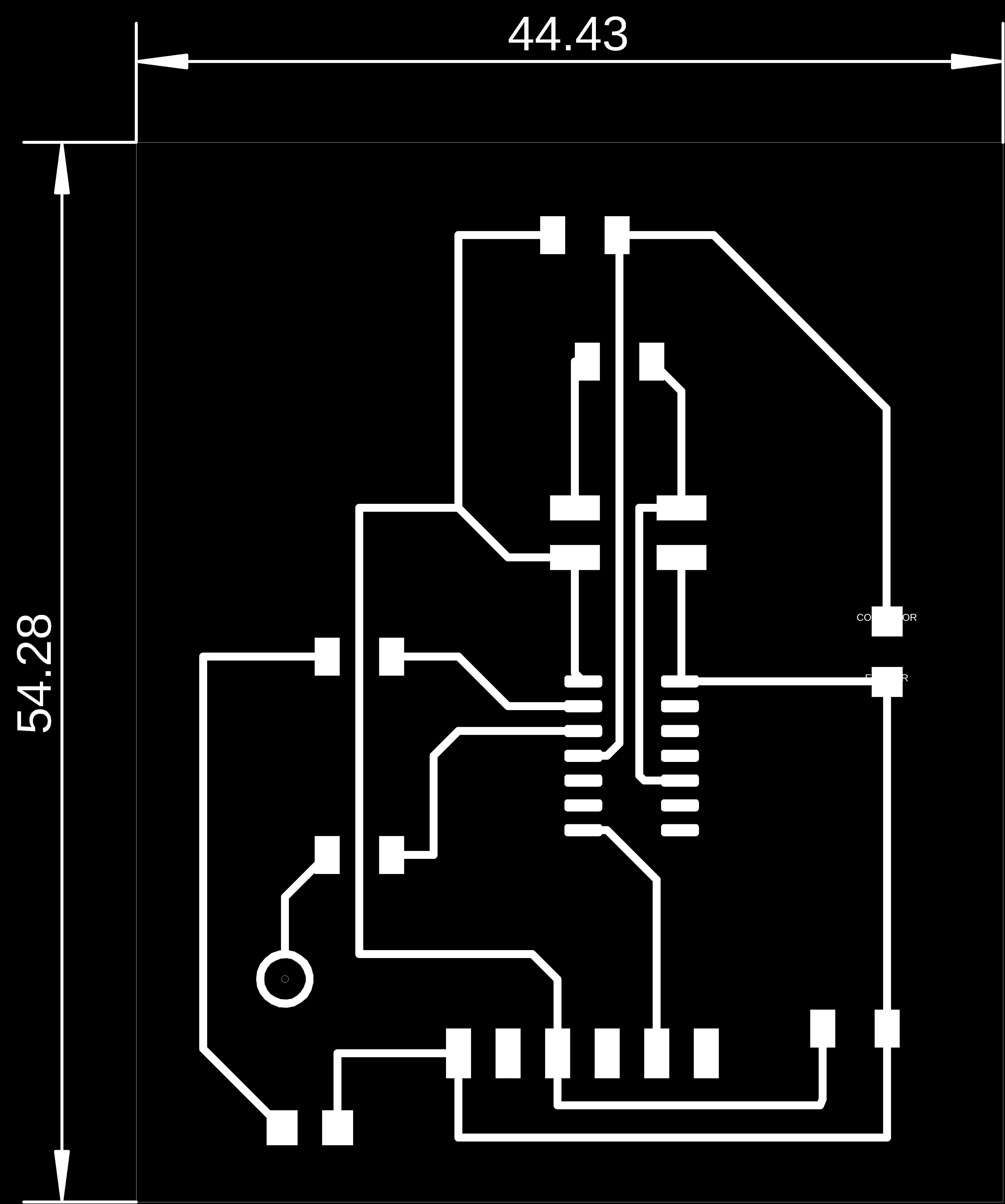
I wanted a little more space for soldering, so I rearranged the board a bit.
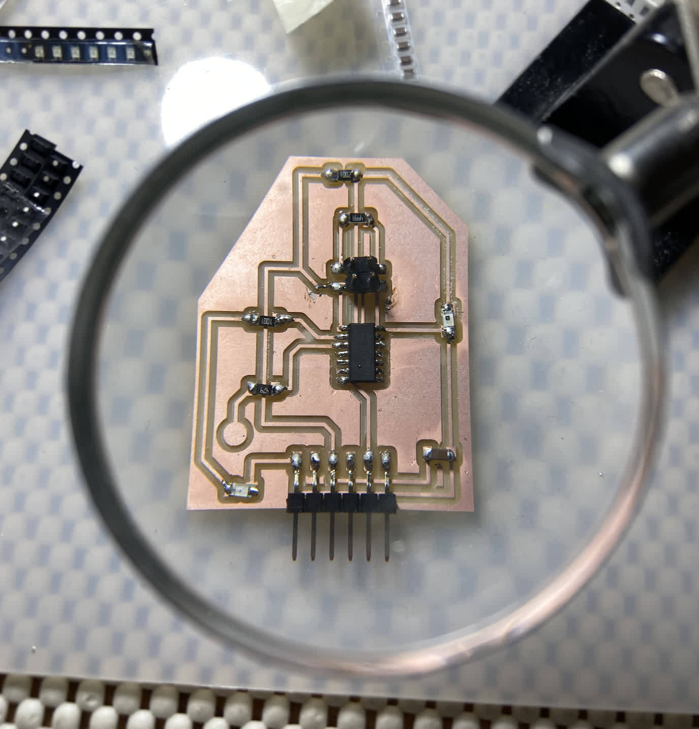
I was in the shop picking up some 3D prints anyway, so I decided to use the Roland machine for milling while I was there. While I have grown to love Clank, I left wondering why I had waited so long to use those machines. The board came out beautifully and in half the time. And I didn't have to keep my computer awake the whole time. I was ready to stuff the board in about 20 minutes. And I think my soldering is getting a little less horrible.
Now it was time to see how this thing interacts with the NeoPixel. I had already successfully programmed it using an Arduino Nano using some modified sample code, so I wanted to see if the ATtiny1614 could just receive that same code and spit it out to the Pixel. Didn't work. Naturally, I sought a helping hand as I was working through the errors. Anthony once again graciously offered his expertise and called out a detail I missed.
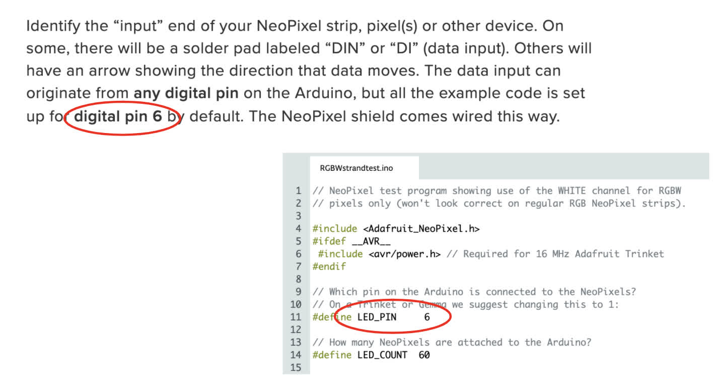
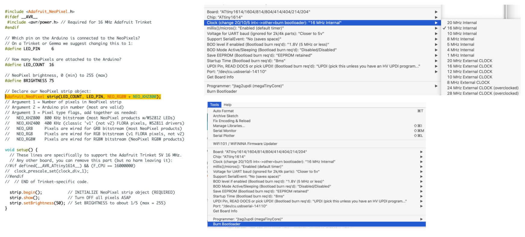
According to the NeoPixel Basic Connections page , the sample code sets the default data pin as D6.
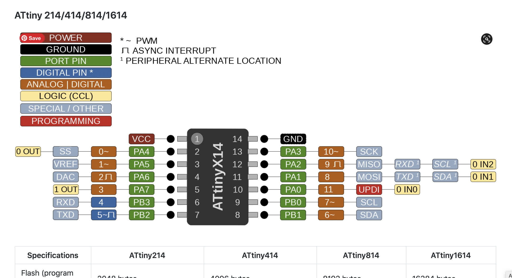
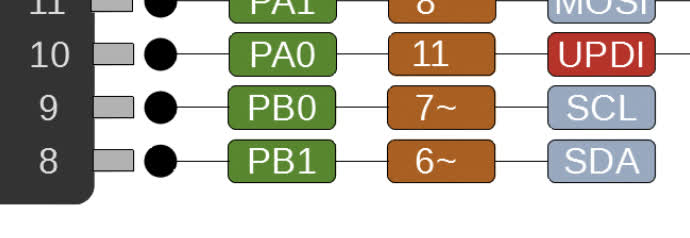
Anthony kindly pointed that out and pointed me towards our favorite megaTinyCore Arduino reference chart to see what pin on the ATtiny1614 corresponds to the D6.
I adjusted the schematic to reflect the pin switch.
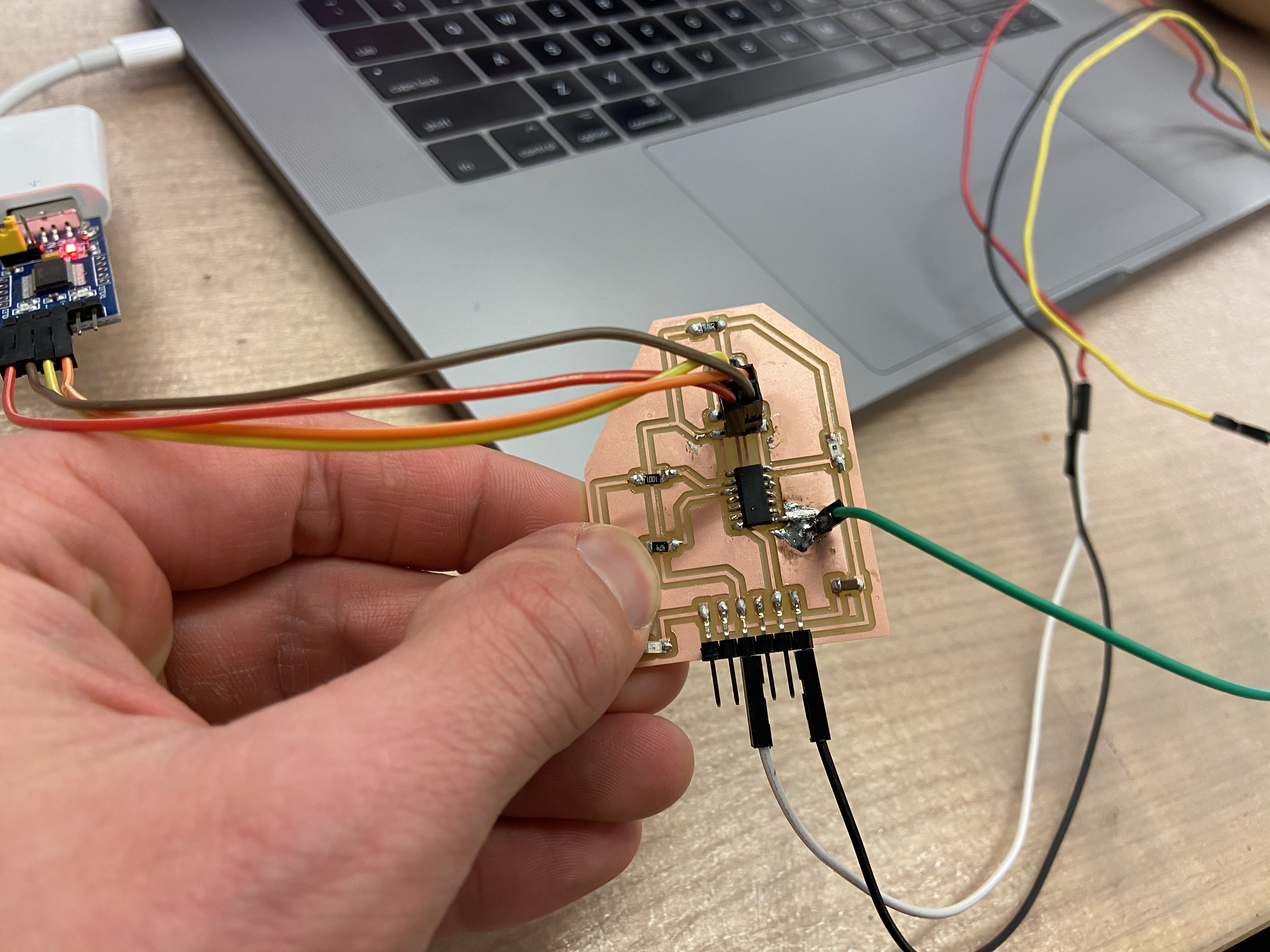
But I wanted to use the beautiful board I already milled. The fix didn't really look super pretty, but it looked like it should work.
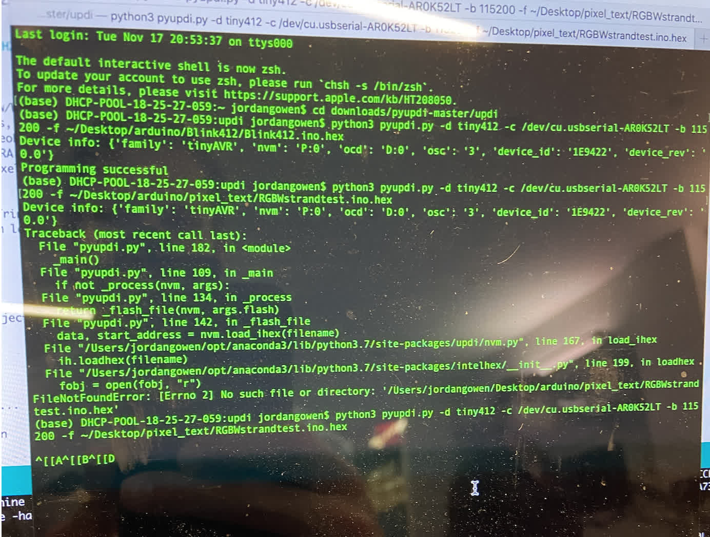
So with an apparent working board, I wanted to prep the hex file for programming. Unfortunately, we ran into an error.
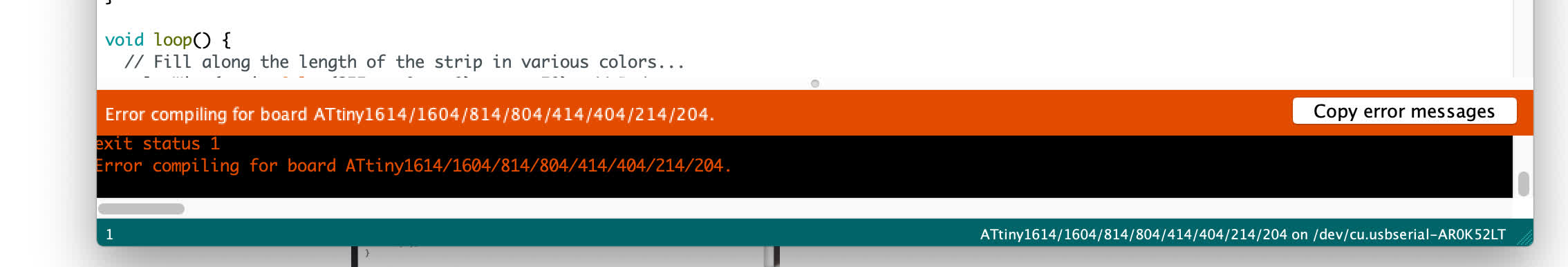
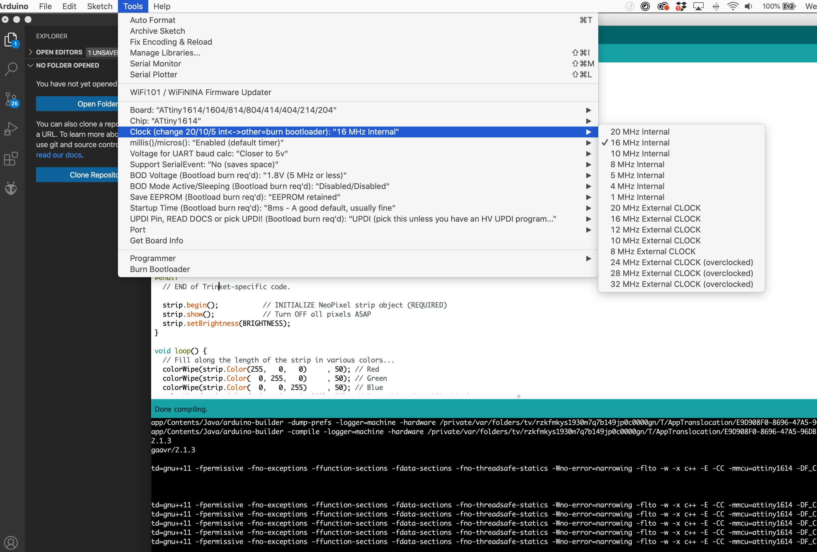
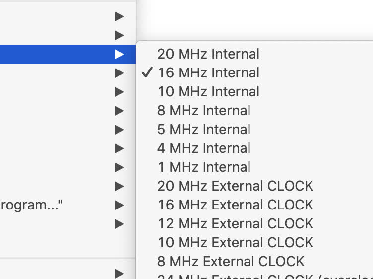
I needed to download the AdaFruit NeoPixel Library and add it to my IDE examples library. I still got errors when I tried to verify the code. Anthony helped me figure out that the "clock" settings in "tools" in Arduino needed to be switche from 20MHz to 16MHz.
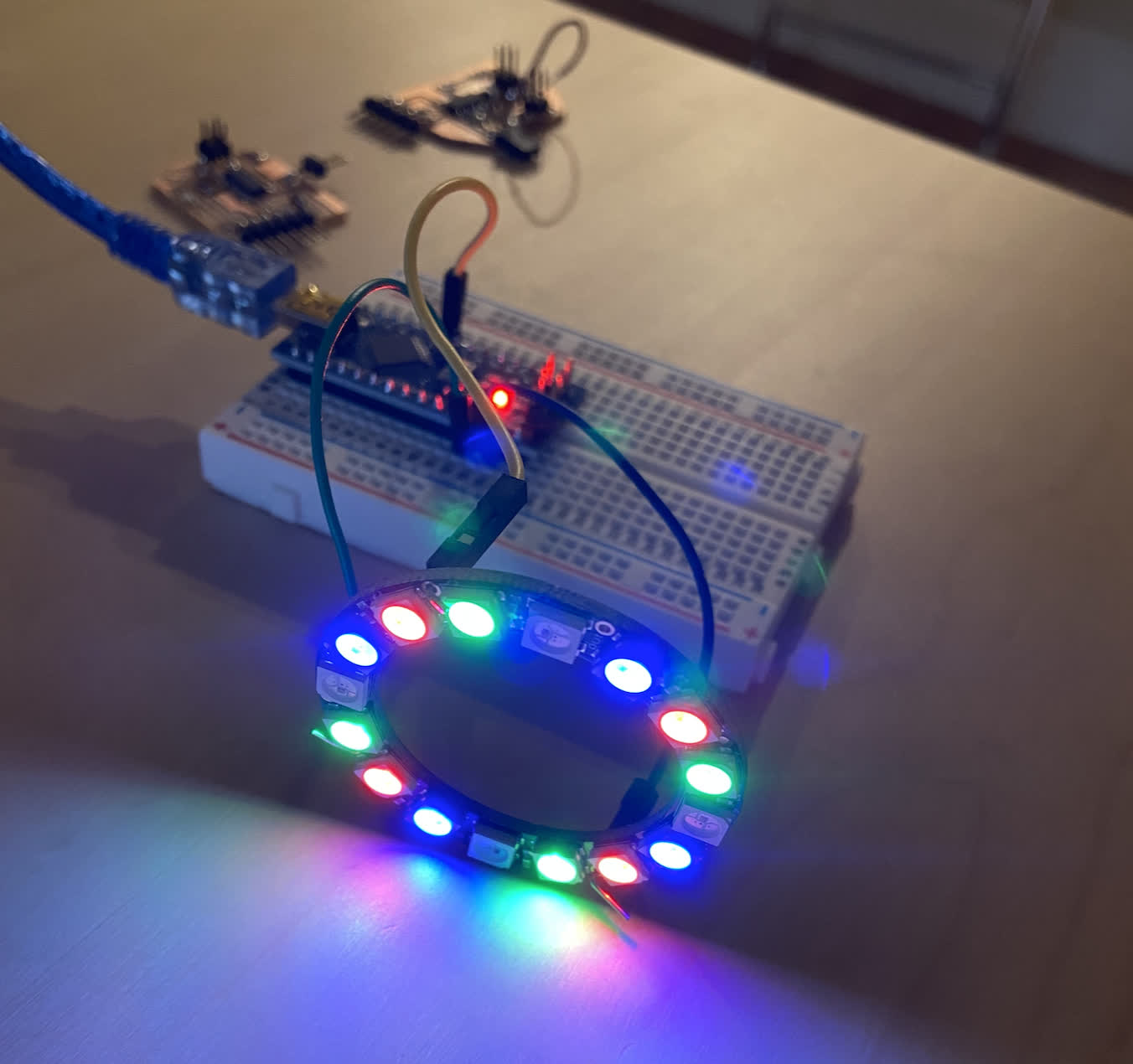
After that, it worked the way it was supposed to, and I wired up the board to the Serial adapter and the Neopixel
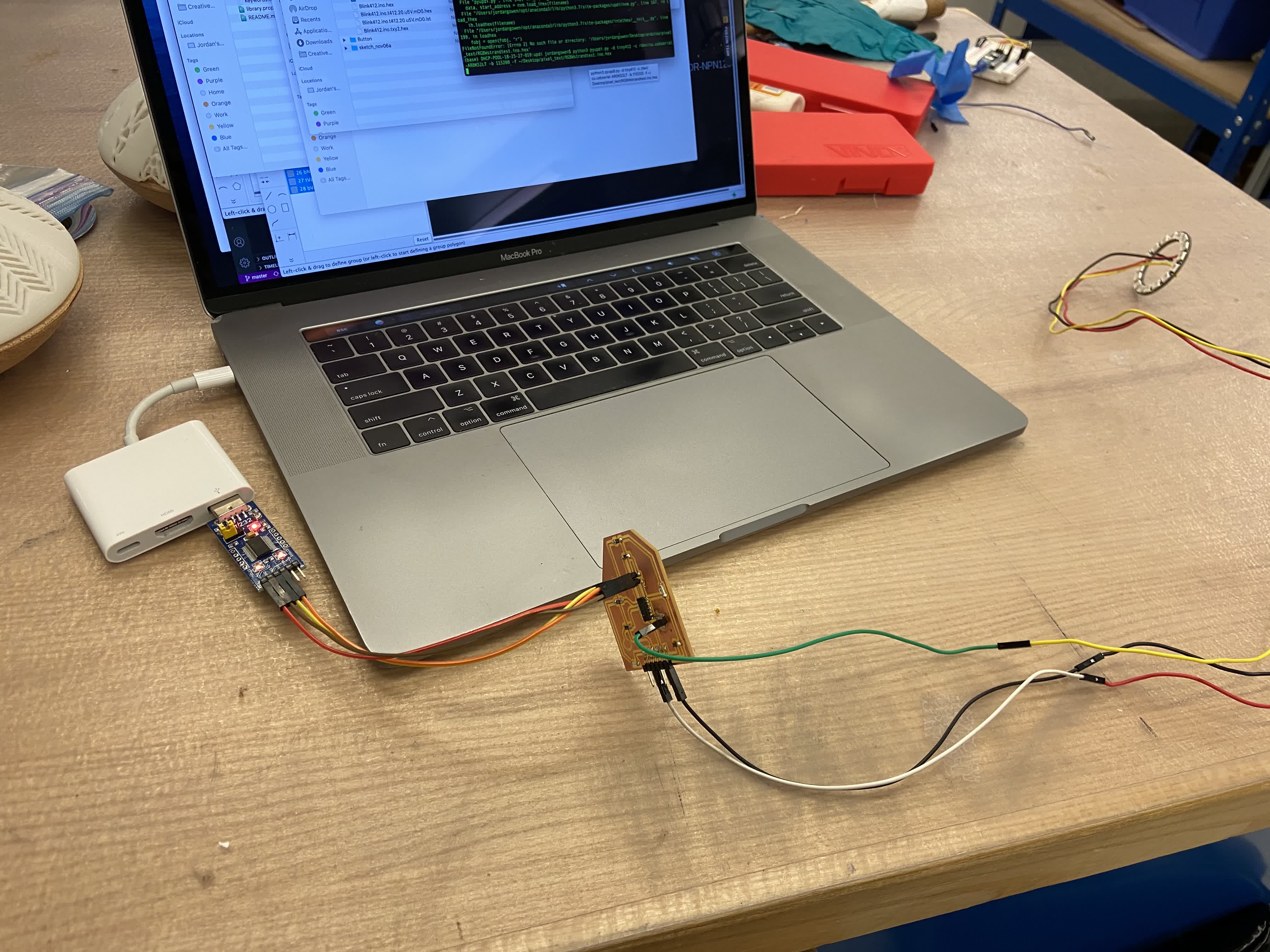
and I ran the code...
The Serial adapter continued doing that for about 2 minutes. Apparently pyupdi can get stuck in a loop, and you just have to shut it down and reboot it. I did that, and the next time ran the code, I got something.
It didn't quite do what I wanted it to do. Anthony suggested I take a look at whether this is an ATtiny series problem when it comes to the NeoPixel. I will need to check that out because if it is a compatibility problem, I'm gonna need to look into using other chips.
NeoPixel and ATtiny woes:
I really like the NeoPixel for its versility. I've used it before with an Arduino Nano, and I found it really easy to program to perform a variety of functions. But when I tried to integrate it with the new ATtiny series chips, I immediately ran into problems.
This is a standard example sketch "Strand Test" for the NeoPixel, running through Arduino Nano. It is running perfectly, so the NeoPixel itself is working.
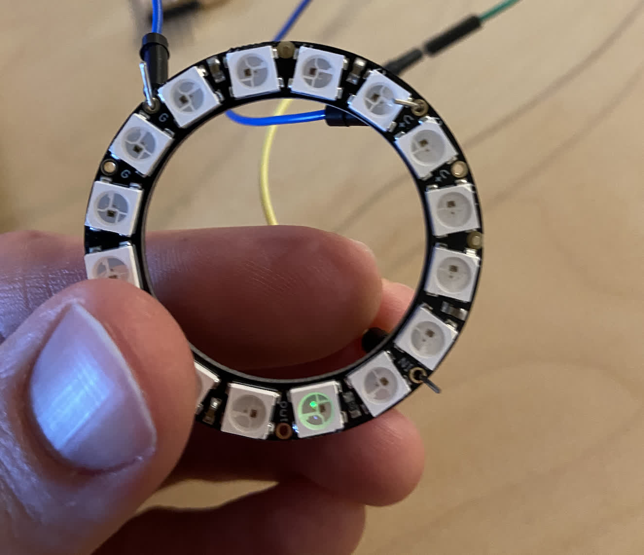
According to the NeoPixel Uberguide, the LED strips or ring need a single pin connection to the board (in addition to ground and power). In this case, I chose digital pin 6 per their example. And I created a 1614 board with the requisite pin hooked up. See the chart for Arduino pin 6 on the board:
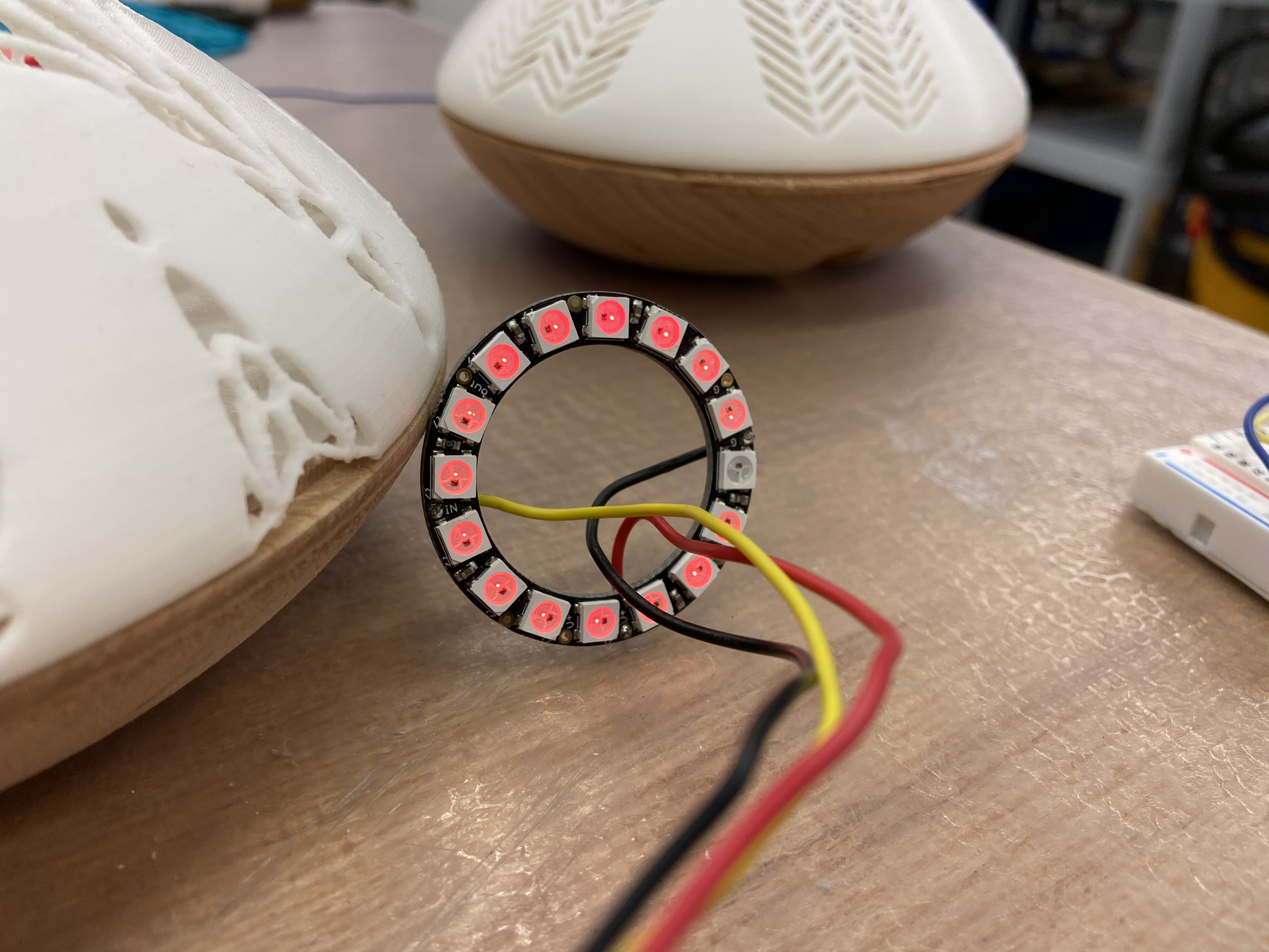
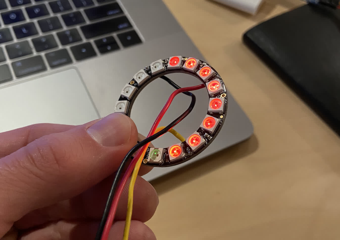
After some board troubleshooting, the connection should work, and the NeoPixel should run correctly, but it didn't. Instead of the full strand test color cycle, I got a few lights to light up and only shining red. This was programmed using the FT232 and UPDI.
This was frustrating. The working theory we came up with was that there was an issue with the ClockSpeed between the ATtiny series and the NeoPixel. I raised an issue asking about this, and I got a variety of responses, which were helpful in considering the reality of pushing farther down this road. I think a viable alternative is to create my own LED ring. And I may still do this, but I also wanted to work with Anthony to see if we could make this work a little better.
I did some pretty intensive digging online to see if anyone had successfully used these components together, and I found a couple.
1. This instructables IKEA Star light. was a good resource to show that these products can work together. It also mentioned that the clock speed needs to be changed to 16MHz instead of 20MHz.
2. This Newton's Cradle project actually successfully used ATtiny1614, which was a good thing to see. It also provided a guide to converting the Arduino Nano into a UPDI programmer.
I showed these to Anthony, and he came up with a few plans to try out. The first was to change some aspects of the code I was running in the Strand Test.
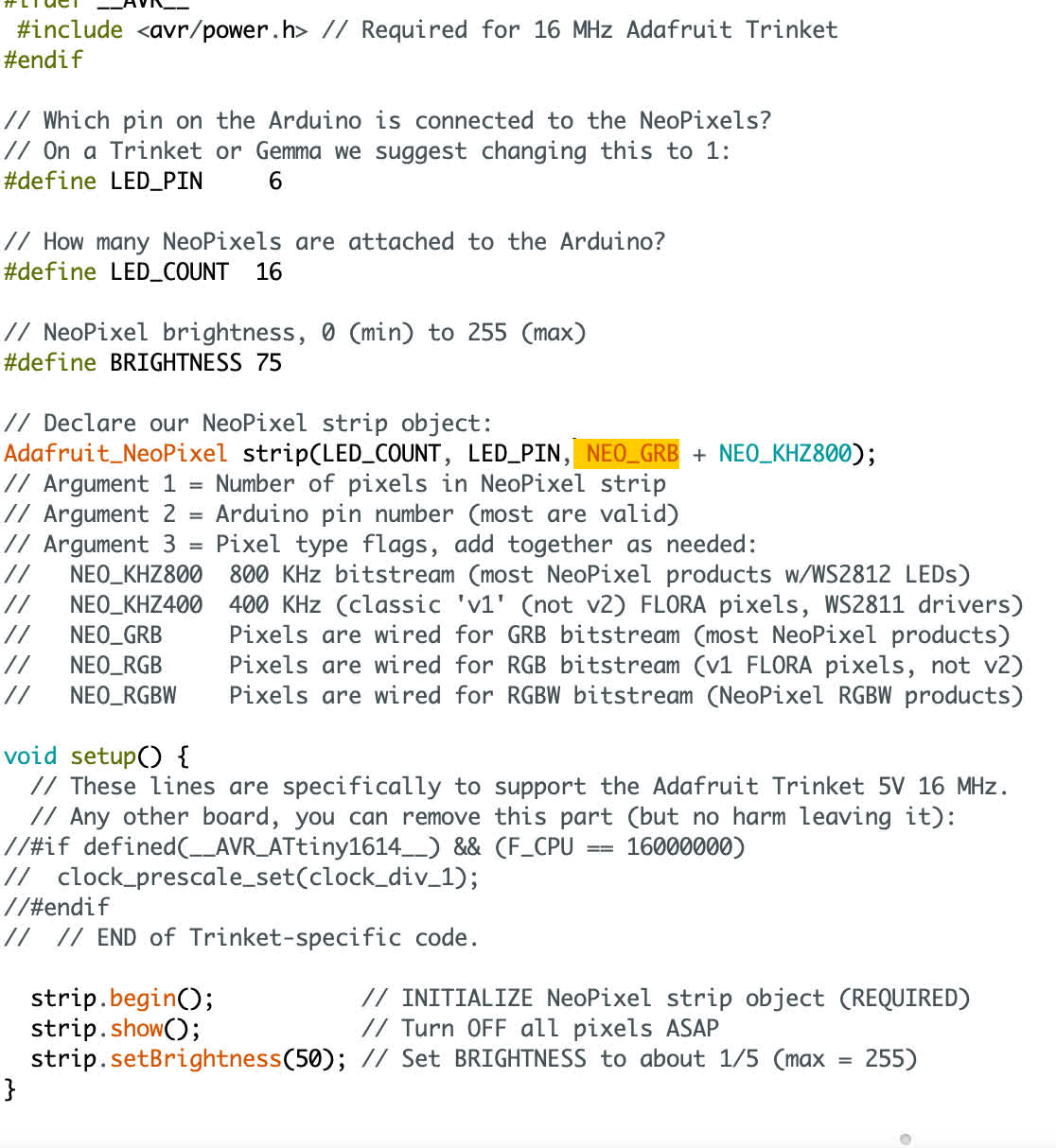
I toggled the the Adadfruit_NeoPixel strip(LED_Count, LED_PIN, NEO_GRB + NEO_KHZ800) line a few times. Changing NEO_GRB to NEO_RGBW for exmple. But in using ftdi, this didn't change much. In some cases it resulted in no light at all.
So the next thing we wanted to try was to convert the Arduino Nano into a UPDI programmer because it should be to "natively" run ATtiny series. Anthony found an even better resource for doing this:
A Step-by-step guide to turn a uno/nano/pro mini into a UPDI programmer
We did this succesfully, and I not able to upload Arduino sketches directly instead of using the hex file method through pyupdi. That said, I ran the sketch to see if the NeoPixel would respond differently, and we got a frustrating non-result.
I tried toggling the same aspects of the code, this time changing NEO_KHZ800 to NEO_KHZ400, and I got a more responsive output. Still not what we're looking for, but I got a red color wipe.
Anthony kindly offered to help me troubleshoot this by purchasing a NeoPixel product of his own. He bought a strip of LEDs and had no problem running a Strand Test on the lights. We think it may have something to do with the compatibility of the 400KHz version that I think I'm working with in the Ring. The strips run on 800KHz, and they appear to run more easily, so I bought some. They should arrive next Tuesday, but I may begin designing my own custom light board as a contingency plan. I can't push this much further. I have other problems that need my attention--namely in the networking department.
The new product arrived on Tuesday, but I wanted to doublecheck my old board with the ring because I hadn't in a while. I had been programming the 1614 boards all day, and had no problem, so I hooked up the board and the LED to my converted Nano programmer, checked the tool settings were at 16MHz, burned the Bootloader, and uploaded the Strand Test code with NEO_RGBW + NEO_KHZ800 selected. It came out working exactly as it should.
I had another one of those moments were I was floored that this thing I'd been working on for days had suddenly started working seemingly out of nowhere. Thinking it might be a fluke of the board, I tried it with my other 1614 board, and it worked with that too. I'm not sure if I changed something inadvertently and didn't track it, but now I have the setup down, and I know that I can make the NeoPixel ring and the ATitny1614 work together, so I'll take it.
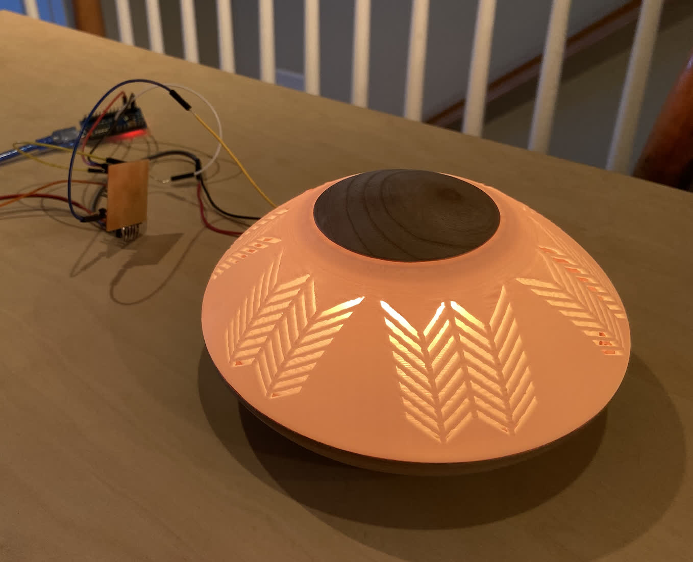
I did some toggling of the NeoPixel code to make sure it was definitely responsive. I also wanted to check it out in the housing. Here's some purple shining from inside the packaging for good measure:
The wiring right now is really ugly. I could shove it all inside the packaging, but I think I'll refine the setup before I do. See the mess of wires:
I was curious as to whether I could get a ATtiny412 board to work with the Pixels as well, so I change the settings in tools and uploaded the code, but I got nothing. I decided to move on for now because I have something working, but I'll circle back to that issue when/if I need to use a 412 board.