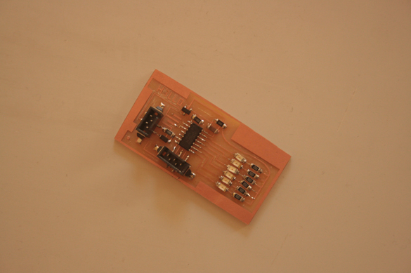
PCB Design
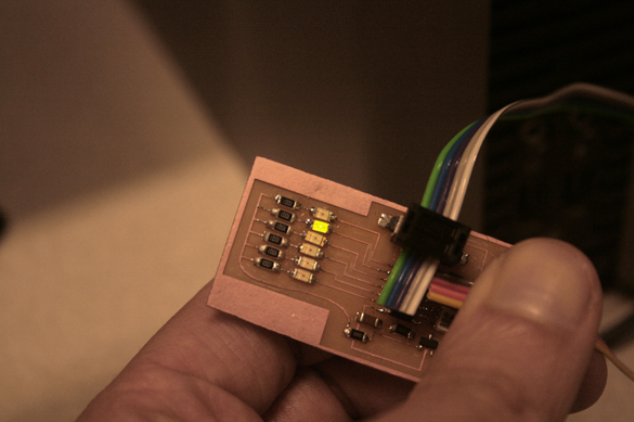
For this assignment I designed a PCB with an array of 6 LEDs. I used the tiny 44 so I had more pins to control more LEDs. I adapted the hello.echo.44 to this new arrangement. The curved line brings voltage (VCC) to the array of LEDs, which are each connected to a resistor and to an individual pin. I used a 0ohm resistor as a bridge, or jumper, between the left and the right part of the circuit.
VCC -> resistor -> LED -> pin
The anode (+) is on the resistors side, and the catode (-) on the pin's side. On my first attempt I forgot to set the crystals speed, which apparently caused a problem on the chip when trying to program it. 'The fuse has changed from 0 to 62, do you want to , etc..'. I replaced the processor and tried again. The line for setting the crystal's speed is:
avrdude -p t44 -c bsd -U lfuse:w:0x7E:m
The settings for milling from a png differ from those for milling from a .cad file. The following image shows the settings for png milling EXCEPT zmin should be set to -0.15 and zmax should be set to 0.1, and xmin and ymin should be set to wherever you want the milling to start.
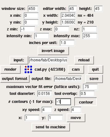
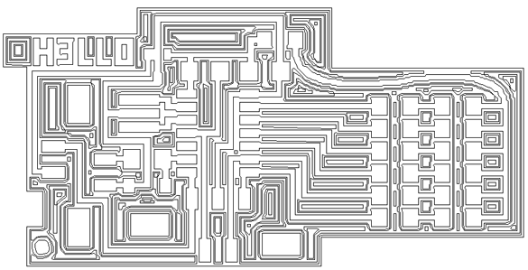
Using a .64 bit, the following are the contours...

It works, but for programming it I ran into problems. Refer to next week's assignment for a more complete description of the errors. |