Demo
Design
For this week's assignment, I made an electronic speed controller to drive a brushless DC motor. Brushless DC motors are commutated electrically, rather than mechanically (like stepper motors), so you need a three inputs. Each input can be high, low, or high-impedance.
I implemented this controller with a pair of h-bridges, which means it could also be used to control a stepper motor or a pair of regular DC motors with the right code on-board.
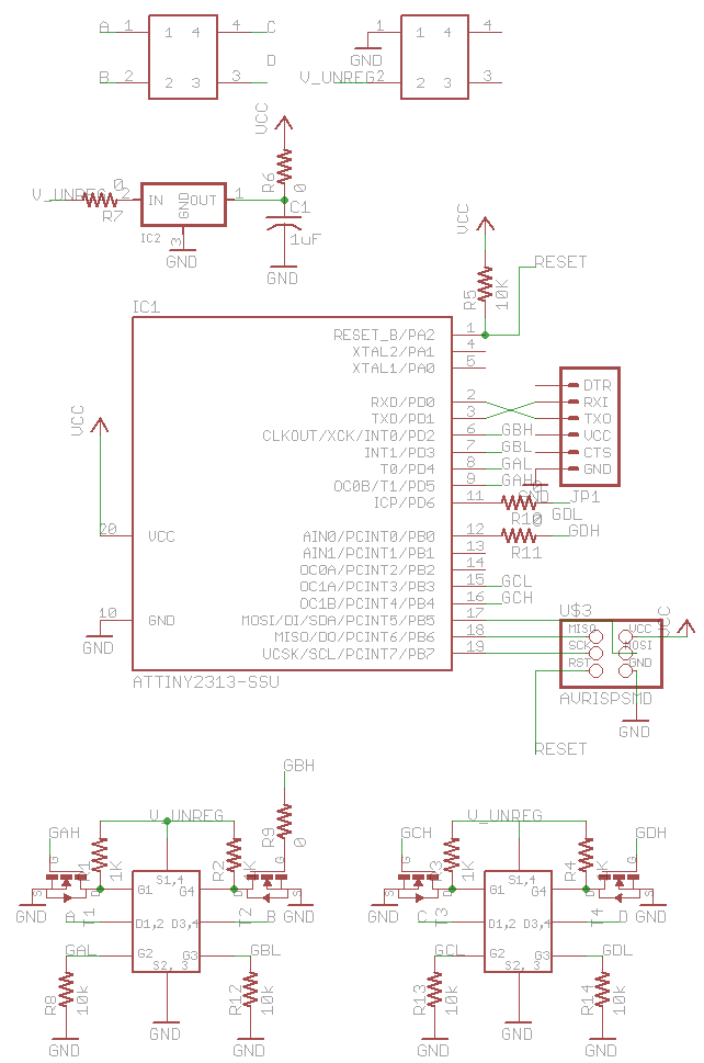
Schematic
The interesting part of the circuit is two h-bridges with high-side nMOS drivers and pull-down resistors on the low side to prevent accidental shorts. The system is controlled by an Attiny2313, which has more outputs than the 44 and hardware serial support.
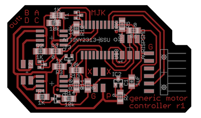
Layout
I tried to run larger traces from the h-bridge lines. Even so, the bridges and board get noticeably warm to the touch when the propellor is spinning up.
The propellor interfaces with the board through a four-pin header, as does the power supply. I used a standard six-pin ISP header and an FTDI header for serial communication out to a PC.
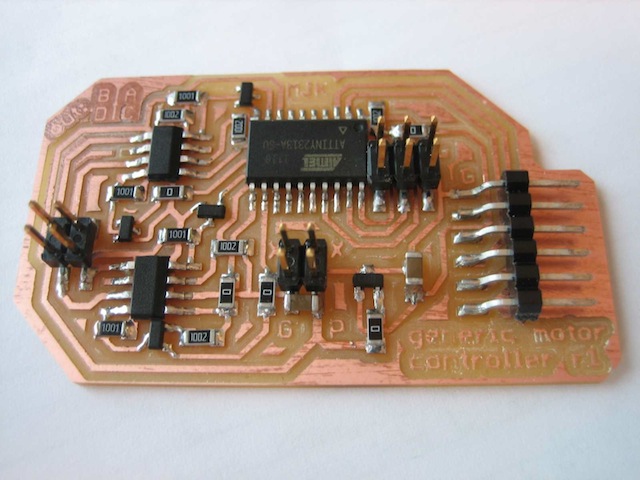
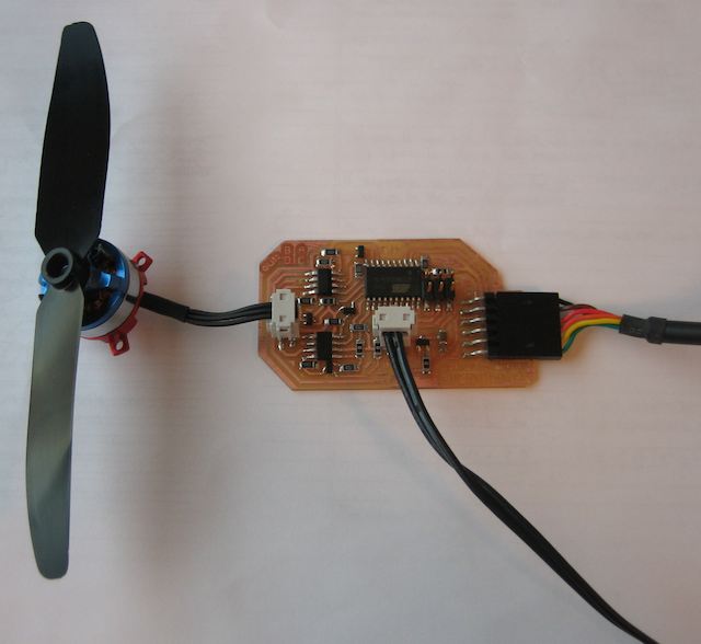
Completed System
I had an strange problem wherein the system restarted whenever I activated the h-bridge. After scoping it, I found a significant voltage drop, so I added more capacitors. There's one sitting on feet of the power input header, and one more stacked on top of the original regulator smoothing cap.
Even with this extra capacitance, the system restarts if you try to turn on the h-bridge without a motor plugged in. I'm guessing that the motor's inductance helps reduce the magnitude of voltage swings.
Firmware
I only blew up one h-bridge while programming this design. Not bad. To minimize h-bridge death, I wrote a set of helper functions with names like pinA_high(), pinA_low(), pinA_off(), etc. to safely switch h-bridge state without ever shorting power and ground.
The firmware cycles through a set of pin states that creates a full rotation. I found these pin states through trial and error, then hard-coded them. It has a timed delay in between switching states, set in software.
The Attiny2313 only has 2 kB of program memory, so it's important to minimize code space. Can you tell the difference between these two chunks of code?
_delay_ms(10);
vs.
volatile int delay = 10;
_delay_ms(delay);
In the first case, the system will optimize since 10 is a constant value. In the second case, it will bring in an entire floating-point stack to convert the delay variable into a double (since that's the input type to _delay_ms). This brings code size from 60% of available space to about 308% of available space.
To deal with this issue, I used the non-floating point delay function _delay_loop_2.
Software
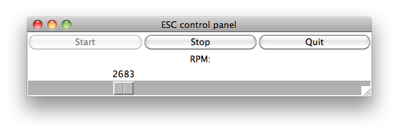
I wrote a quick python GUI to control the board. It does a conversion from RPM to delay values, then passes them on the serial line to the Attiny.
Source
Firmware (includes python GUI)

All source files are licensed under a Creative Commons Attribution-NonCommercial 3.0 Unported License.