Demo
Design
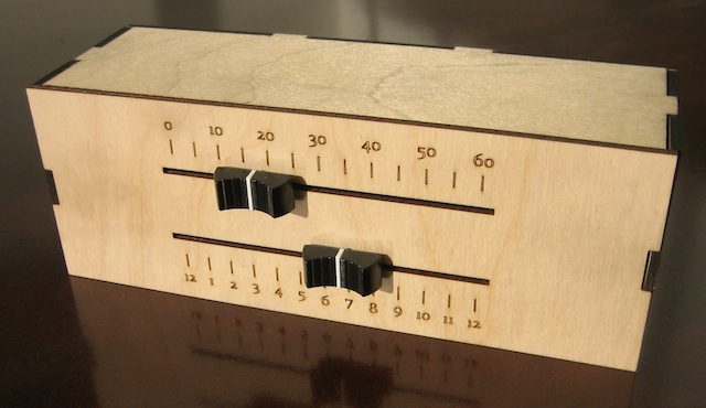
For this week's assignment, I made a clock that uses linear motion to tell time. Two independent layers run in parallel, counting hours and minutes. The clock takes advantage of microcontroller sleep modes to reduce its power usage.
Sliders
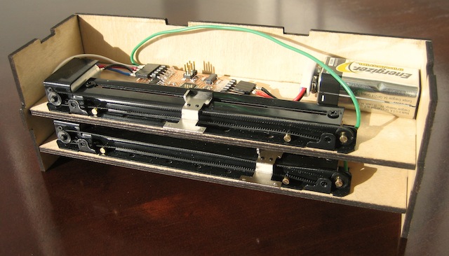
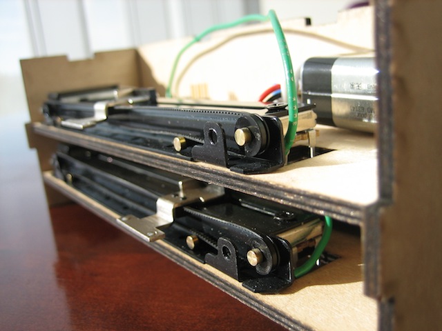
Each slider is moved by a motorized slide potentiometer, which can detect where it is and move along the slide.
The potentiometers have a resistance varying logarithmically between 0 and 10 kOhms. When I ordered them, the product page said they were linear - it got updated while they were in transit.
This little surprise made my life more interested.
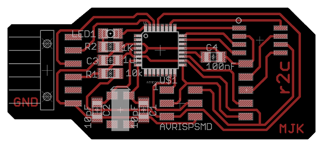
Electronics
I used Eagle to make a controller board based on the ATmega168 microcontroller, because it allows for asynchronous Timer2 operation while the rest of the chip is powered down (more detailed explanation are in the software section).
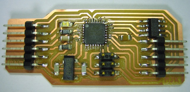
The board includes the microcontroller, an H-Bridge for motor control, a 32.768 KHz clock crystal for timekeeping, an LED, and various other parts.
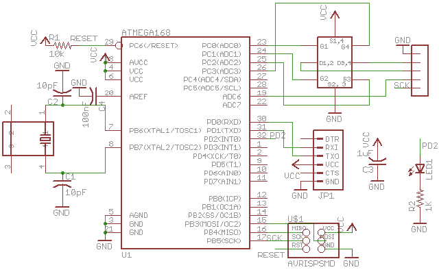
The microcontroller can be programmed through the on-board SPI header. There is also an FTDI header for serial communication (helpful in debugging!), and a five-pin header that connects to the slide potentiometer.
Firmware
I've used enough assembly to know that I like having a compiler to manage my stacks and variables. I wrote the firmware for this week's clock in C then used the avr-gcc + avrdude toolchain to program the chip.
Interesting features of the firmware include:
- Power-saving sleep, with Timer2 interrupts every second to keep time. The microcontroller spends the majority of its time in SLEEP_MODE_PWR_SAVE, where the core is inactive but Timer2 continues running asynchronously.
- The use of Timer0 as a PWM controller for motor-control purposes. I didn't wire the H-Bridge to any of the automatic PWM pins, so I implemented it in software.
- Interrupt-based ring buffers for serial input and output. These let you send and receive data without worrying if the last character has made it all the way out. They also don't block normal operation when running, since they are interrupt-based.
- Two-level ADC reads. The controller reads an ADC value with a reference voltage of 1.1V, then switches references and reads the ADC again with a 5V reference. This helps get decent resolution across the whole range of the logarithmic potentiometer.
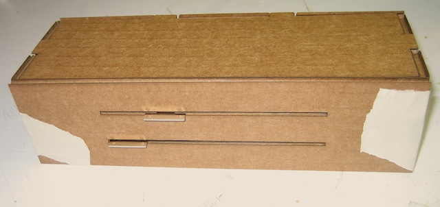
Case
I designed a case as a cad file, then fabricated it out of 1/8" scrap wood on the Universal laser cutter.
Of course, I made it out of cardboard first:
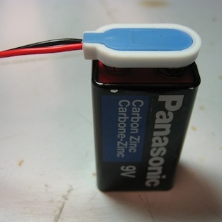
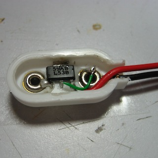
Power System
The project needed to be run from 5V, but I hadn't though to include a regulator on the board.
I solved this problem by making a clever modifications to a 9V battery plug:
Results
Source

All source files are licensed under a Creative Commons Attribution-NonCommercial 3.0 Unported License.