Electronics Design
Design the Board
I designed my board using eagle with the following tutorial on sparkfun.com.
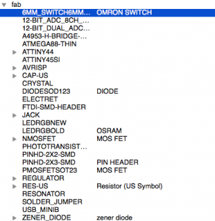
I used the fab.lbr, to drop parts library on my board. Once you download the fab.lrb, click on add a part, then you will see the parts list for you to drop in. The preview window is very helpful when determining the package.
I used hello.ftdi.44 layout as the template and added 3 LEDs and on button.
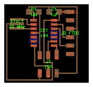
Using Net and Wire tools, your Schematic should look something like this. PS: Make sure you use GND and V+ 5V in “Supply 1″ Part list. This is the professional way to do it.
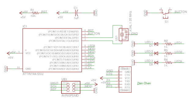
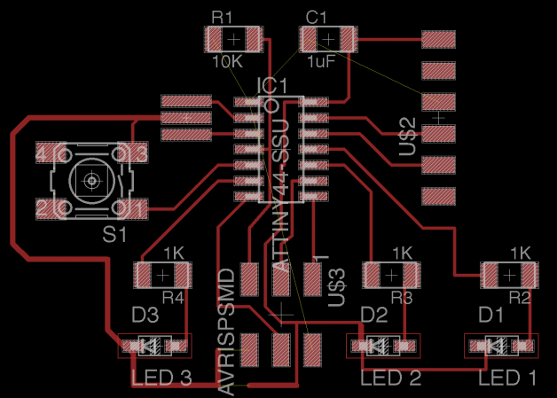
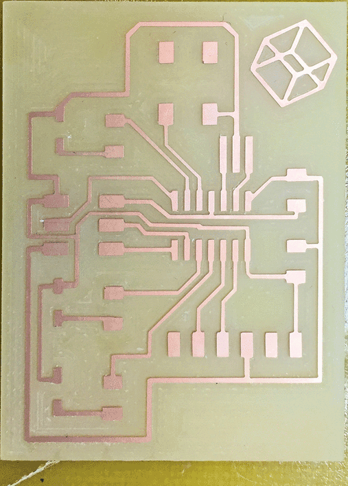
Once I lay the board out, I generated the board within Eagle. I moved all the parts to the center and tried to arrange them somewhat like the hello.ftdi.44 layout, but with spacings that would fit my buttons and LEDs. There are 4 open pins on ATtiny44 and I used all of them. (I probably should put the button on the digital pin, as later I will find out. It’s also waste of a PWM pin for fading the LED)
Export the Board
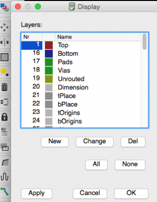
Click on Layer Setting icon (Blue, red & green square layering icon), and only leave the Top layer on. that will only give you the wire outlines for you to mill later.
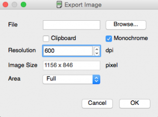
File > Export > Image … as PNG file at 600 dpi, and make it black & white.
To create the outline for the milling machine to cut, I used photoshop. I created 2 files, border file and trace file. I opened the trace file in photoshop and do Image > Canvas Size, and increase the size by 0.1 inche for heigh and width. For the border file, I did the same thing as for the trace file, but I then inverted the image, Image > Adjustment > Invert, and then used Marquee tool to select the center part, then fill it with white.
Making the Board
If the milling machine started to do something artistic, it’s probably the communication issue, talk to your TA about this.
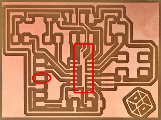
Opps, I made 2 mistakes.
#1. I forgot to wire the TX pin after I change my schematic.
#2 The wires in the middle of the IC are too close.
I fixed #2 by doing the DRU command in Eagle, decrease the line size, and make the snap grid smaller.
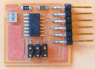
Final product. The right one is using the -1 filling path, 4 for the left in Fab Mod.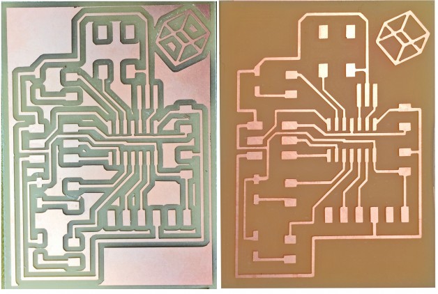
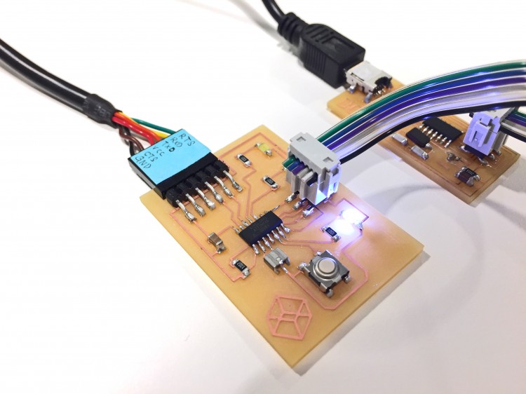
Stuffing the board.
Tips for getting Arduino IDE working on your own board
#1. Here are the json URLs for all Mega & Attiny board with all sorts of processor speed (1, 8, 16, 20 mHz)
Paste The following URLs into the Additional board section. (I also included other Atmega board like 382p)
#2. Burn Boot Loader using your FabISP from previous class or AVR MII
#3. Done!
All you need to program now is the FTDI cable, you can also use ISP pins to do all your programing and take out the FTDI cable all together (you might want to break out the TX/RX if yo wanna do serial communication)
You only need to do this once.

Upload Your Sketch to Blink LEDs
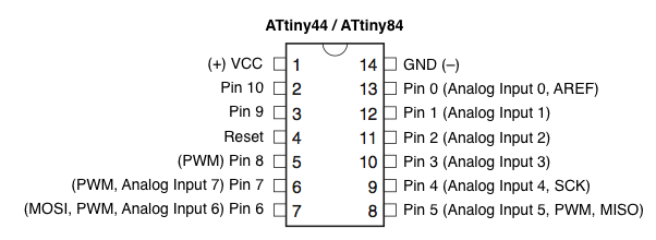
Use it like Arduino, here is the pin map.
Here is my blinking code & video
Using internal pullup to sense the push of the button since I don’t have a pull up resistor on the board.
pinMode(buttonPin, INPUT_PULLUP);
1 2 3 4 5 6 7 8 9 10 11 12 13 14 15 16 17 18 19 20 21 22 23 24 25 26 27 28 29 30 31 32 33 34 35 36 37 38 39 40 41 42 43 | const int buttonPin = 8; // the number of the pushbutton pin int buttonState = 0; // variable for reading the pushbutton status int switcher=0; int delaytime =80; void setup() { pinMode(buttonPin, INPUT_PULLUP); // using pullup to sense the push of the button pinMode(7, OUTPUT); pinMode(3, OUTPUT); pinMode(2, OUTPUT); } void loop() { buttonState = digitalRead(buttonPin); if (buttonState == HIGH) { switcher = 1; } else { switcher = 0; } if (switcher == 1 ) { digitalWrite(7, HIGH); delay (delaytime); digitalWrite(7, LOW); digitalWrite(3, HIGH); delay (delaytime); digitalWrite(3, LOW); digitalWrite(2, HIGH); delay (delaytime); digitalWrite(2, LOW); } else if (switcher == 0 ) { digitalWrite(2, HIGH); delay (delaytime); digitalWrite(2, LOW); digitalWrite(3, HIGH); delay (delaytime); digitalWrite(3, LOW); digitalWrite(7, HIGH); delay (delaytime); digitalWrite(7, LOW); } } |
Other Tips tricks
Picking the right resistor for the LED
http://www.evilmadscientist.com/2012/resistors-for-leds/