Input Devices
15 November 2017 | By Casey Evans
“I’ve wanted to tell you that I’ve changed. Irrevocably. Permanently. My soul is richer and my heart is fuller in brokenness than it ever was without. I’ve learned true despair, and it’s made me learn to appreciate true joy.” -Lexi Behrndt
![[ultrasonic.jpg]](img/ultrasonic.jpg)
I exploded one of these (smoke and all) in
undergrad. I got to keep it as a memento
and it used to sit on my desk staring at me
and asking me to think about what I'd done.
Assignment
Class Notes
Other People
Today is the one exception to the no late rule since it’s expected.
CBA Shop
Why pancakes? They’re not an easy problem. Based on batter viscosity. Hard to figure out the workflow. Electric griddle fit perfectly. This is Anna’s group. I want one of these. Dunno where I’d keep it but it’d be a fun squadron activities room thing. Toolpathing with CAM in Fusion. “There was this thing. And it could be made by someone who’s name was Jake.” Melting is a terrible sign. CBA team is the all star team. I almost think that the all star team should be on the worst equipped lab and the least experienced team should be on the most equipped lab. Unless that’s already been tried and it just results in things never getting used (though if they’re so motivated they would probably go to the other shops anyways). “Unless you’re sure you should be paranoid about speeds and feeds.”-Neil. Note upcut or down cut. Maybe shallow downcut and deep upcut. Can do it all on aluminum in about the same time now (not as good a material to learn on though). Z axis to control end effector. Mods breaks Chrome, Neil has Chrome fix what he breaks. The CBA team met a permissions issue in Chrome so they’re going to add an issue to the mods project issue tracker. 7s optimal gradient time on pancakes. Stateless machine with networked nodes instead of TinyG would be good.
Architecture Machine: VanGo – A Watercoloring Machine
What if it just drove around instead of having a test bed. Y axis is infinite. Don’t reach in, poke it and fix it when the end mill is shaking around. Don’t do that if you want to retain your limbs. Bandsawing all press-fit joints. Also drilled holes on corners to fix curved edges (from milling). Don’t have sharp corners where the flexures join. “Most watercolor CNC machines have a palette.” Okay so, wow, this is a thing. Cool. Reminds me of the automaton in Hugo.
EECS
Acrylic glue is a solvent.
Harvard
Luminescent emergency roll. Corgi.
Thanks to Jake for the prep and help. Class doesn’t have a midterm but this is like a midterm. It’s a very unusual amount of work. -Neil. Works. Not a long lifetime. Good for making mistakes. Aluminum has better tolerancse. Each machine can make a machine slightly better than itself with trochoidal milling. It’s good to learn all the ways you can fail. Usually have to do with system integration. Like fasteners sticking and bumping something, wires tugging against motion and so on. “I’m doing astrophysical units.”-Neil. I don’t remember the context but that’s an interesting thing to say. Machines to be ubiquitous not rate limiting. Something for a cattle rancher (someone in the class’s dad). Single thing they still need people for is to secure the fasteners. Fellesverkstedt. Fun to write submodules in mods (empowering). Help to document.
This Week
Add a sensor. Read it – get data from a sensor and in some way do something with it (act on the information you got in). Tiny45 works well. I’m not sure how to get a daughter board to work with another board. Comparator is fast. ADC also works. You can compare against known references. 10 bit converter in Tiny45. You can subtract two voltages (good for tiny changes or things with a moving background). It has an internal amplifier. 15k samples per second. It’s okay. You can go higher but bits get less reliable as you go up.
Buttons, FTDI serial to USB communication, pull up resistors. Capacitors for timing. Down and up sends d’s and u’s to an interface. Processor slower than clock to save battery life. Look for put_char(). Character routine takes a bit of time so no need for separate debouncing. Pyroelectric infrared motion sensor detector. Not an absolute sensor, it senses change in motion. Maybe this week I can make the ocarina with a motion detector near the mouth hole. Based on total thermal flux though so it doesn’t work well outside or areas with lots of light. “Good for turning on the lights in the bathroom, but not much else.”-Neil. I maybe should also make a very generic board with a mega to have more pins (and create a pin bed) and then just plug in different things to the pins. Ultrasonic detector only works if you have a good reflecting surface oriented at the detector. Not good with absorbing material or materials at an angle. “Commoditized” down to a couple of dollars. Trigger pulse to sonar and then listen. Sonar returns rising edge for start and falling edge for echo received (time from pulse sent until echo received). Python program for bar graph. Simple lidar. Might be fun since it’s kind of relevant to my research. Maybe have that to sense proximity to face. Hall effect magnetic field sensor. It’s signed so the two directions have different signs. It’s sensitive enough to measure Earth’s field. Compass? Nothing makes sense without the datasheet. Use registers to control ADC readings. Oversampling and averaging. Then using noise shaping (I think). Can run to interrupt. avr-lib types. Accumulator. Sending low, medium and high bits out separately. JavaScript instead of Python is possible. Chrome serial. Node is JavaScript outside of the browser. Runs a tiny program as a server. Talk to server talking to device. Maybe try using mods. Thermometer. Thermistor. RTDs better at higher temperatures. NTCs better at room temperatures. Voltage divider wastes most of the resolution. Use a bridge instead. It’s a square of resistors. Measure small changes in small signals, not small changes in large signals.
![[wheatstone.png]](img/wheatstone.png)
Image courtesy of Electronics360
Choose a reference voltage. Bathroom faucets IR reflected light (see Neil’s example on the LED on/off light differences). Phototransistor that doesn’t see visible light. There’s actually an IR one and a visible one in the inventory. Phototransistors have the photosensitive part on the gate. Smaller parts can be more sensitive than the resistor. Synchronous detection. LED sends out light, some light comes back, chop LED on and off. Subtract on and off times. Modulating to a higher frequency. Measure someone walking past a light sensor. Only finds light from the source. Magnetic field sensor on carriage to tell it to stop. Or to know when things are close, a box is closed, and so on. Gravity is acceleration so an accelerometer would be able to sense that (different right side up and upside down). Cute devices. Reading the accelerometer requires some reading and writing to it. Chip scale packaging. New skill required: reflow soldering. Tin the board to help the solder wet it. Then put solder bumps on the part pad. Turn on a hot air gun in the vicinity of the board. Slowly bring part into hot air. Surface tension helps align it (solder wants to stick to solder). Reflow oven stuff can be done in a frying pan or a toaster oven (just note that solder often has lead in it). Step response is “the best sensor of the week.” Touch pad. Can I emulate a touchpad to do good scrolling on my laptop? Can also do proximity sensing.
How a step response sensor works. (see picture) Put out a step up and step down. Humans have internal resistance and capacitance. They also have external capacitance. Dielectric constant of paper pad tightened magnetic fields.
Rotary capacitor. Used for tuning radios in the old days. Rotating changed the capacitance and therefore was an angle sensor. Tilt info if tube with liquid put above it. One trick in the code: turn on charging pulse and read AD. Charge up and charge down. Varying baseline.
MEMs microphone requires reflow. Grab batches of data to then display. Analog interface is nice. Has conditioner in it. Requires a regulator to get to 3.3V. Not high fidelity audio. Ordinary quality. Piezo disks can measure vibration. Force sensing resistors are terrible. Strain gauges. Elastomer (thin foam). Measure capacitance across it to measure force. Surround sensing part with high level signal. Calibration in stiffness of foam. Video models get cheaper and easier. They speak I2C. Webcams are “comically” cheap. NXP Development boards (linux). Mess around on mods with webcam. Use web RTC and JavaScript to do it in a browser. Recitation at Harvard before class next week (due to Thanksgiving). How to design (almost) anything. Arts and crafts with a vinyl cutter can do almost anything.
Training Summary
No training this week.
Assignments
Individual Assignments
So this week I will remake my metronome board so that I have a less fragile version. The changes I plan to make are (1) use a dab of hot glue on the ISP header to avoid the structural failure from the last board, (2) create pin headers on pins PA2 and PA3 so that they are usable with a daughter board and (3) build a battery pack that is generic and reusable with other boards. Hmm. I should also try coding in another environment, or translate it all into assembly since that's the other language I know. Or VHDL I guess, but I thought that was only really for FPGAs. Anyways, my other goals will be to build a sensor array daughter board with a few sensors of interest. Probably the one Neil likes (step response), temperature, lidar, and an LED/photodetector setup since those are all interesting in regards to my final project. Hmm. The speaker is magnetic so I might be able to use that to create an integrated system of PCBs. I'll add a magnetic sensor to my daughter board as well. Maybe I could have a system where when the speaker is put in position it outputs the Zelda "properly positioned item" sound. Probably the real goal for this week is to make an Ocarina using an ATMega (it will need 5 pins for 5 buttons, 1 pin for the speaker and maybe one pin for a sound or distance sensor that gates the output so it only plays if the ocarina is near something like a face). Level 2 Ocarina would track the order of the notes played and if you play one of the sequences from the game it will complete the song for you. This may be challenging since the songs are 5-8 button presses long and it would need to be able to handle that. Another struggle would be that one button should be on the bottom of the board to properly approximate an ocarina.
But I must also be reasonable. I am exhausted for a collection of reasons and I have a limited time scale for this week since I have a friend coming in tomorrow night who I need to be a good host for. With that in mind I will focus on working the three priorities expressed above before Wednesday. The ocarina board I will save for a later date, perhaps after the completion of the course. In order I will (1) redesign the board with pin access (2) design the sensor board with connections to a lidar, temperature sensor (if possible with some planning to connect to a meat probe), magnetic sensor and LED/photodetector setup (3) contruct the boards with battery capability (4) program button press control of LED (5) program temperature sensor output on computer (6) program magnetic sensor to turn on LED in proximity of speaker (7) LED with lidar (8) LED with synchronous setup of LED/photodetector. If I get all of that done I'd like to keep working on the metronome. If I get that done I'll move on to the Ocarina. The goal is to get to and through step 5 at a minimum. Step 4 is the minimum acceptable threshold.
And I got to step 4! But not without some adventure. After I do this initial write up I'm going to try my hand at ADC until maybe 1 am and then get some sleep. I think a basic interpretation of ADC will get me traction on both the Hall sensor and the thermistor. I'll save the step response and synchronous for after that, but I will go to sleep before trying the thermistor (I'm just doing the Hall effect sensor for now). Anyways, I feel I should describe the adventure. It started with me going to the lab--oh, well I guess before that I redesigned my metronome to get access to the two unused ports on the right side by adding pads for pin headers. I'm not going to put the board layout here because it was wrong (more on that later) but the schematic didn't change so we still have:
![[better_schematic.PNG]](img/better_schematic.PNG)
R1 is a 10k resistor for timing, R2 is a <1k resistor to current limit the LED (it must be greater than 125 ohms to not blow the LED), and R3 is representing the 8 ohm speaker. C1 is a 1uF capacitor and the resonator is a 20MHz resonator. The new traces can be found here.
I also designed the sensors board to interface with my original board using the two new pins I freed. I looked at Neil's basic circuits to pull the essential elements for the sensors out and add them to the board. I decided to use 2x2 pin headers so I could easily switch from sensor to sensor (right now I'm using individual cables since I didn't bring wire cutters home with me). I think the only real change I made was the direction of the LED. I prefer it going down to ground rather than coming down from VCC. Personal preference (I hope). Here are my sketches:
![[sensor_sketches.png]](img/sensor_sketches.png)
I then turned the sketch into a schematic:
![[sensors_schem.PNG]](img/sensors_schem.PNG)
Where R1 is the current limiting resistor for the LED (>125 ohms), R2=R4=R5=R7=10kohms, R3 is a 10k NTC thermistor, R6 is a 1Mohm resistor, and T1 is a Hall effect sensor. Unfortunately I didn't plan as well as I expected and my 2x2 assignments are all over the place and listed below. They correspond to the labelling in the schematic and later to the board layout since I didn't rotate them at all. I guess a tidy ribbon cable is not in order for this board just yet.
![[pin_labels.jpg]](img/pin_labels.jpg)
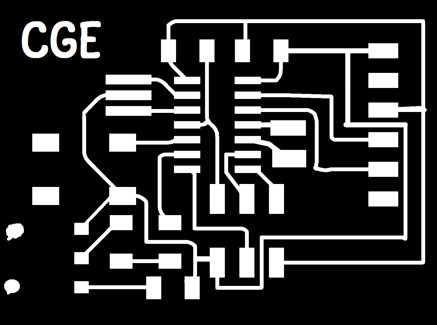
The schematic then became a board layout:
![[sensors_board.PNG]](img/sensors_board.PNG)
The traces are here and the outline is here if you want to make your own. But on to the real story. So I go to the lab, and of course it's like:
![[lab_closed.jpg]](img/lab_closed.jpg)
Which is unfortunate because I had hockey 19h-21h. So I asked my friend Anna if she was going to be in the CBA Shop and whether I could join if she was. She said she'd be around 21-2130 so I went right after hockey but her previous event went late and, well, I didn't get to machine that night. I went in the next morning with some extra success. But for some reason the first time I machined it it messed up on the resonator traces.
![[take_one.jpg]](img/take_one.jpg)
I tried again with 3.5 mm/s and what I thought was a lighter cut depth, but was accidentally an order of magnitude greater, producing these horrible outputs before I realized the issue:
![[speeds_n_feeds.jpg]](img/speeds_n_feeds.jpg)
I got it to print mostly right with 3.5 mm/s and 0.0047in cut depth but I changed the cut depth to 0.0045in and as you (maybe sorta almost) can see in the comparison below, the lighter cut depth helped to cut down on burrs.
![[burrs_or_nah.jpg]](img/burrs_or_nah.jpg)
So I soldered everything and hot glued the ISP headers and then--oh horror!--it didn't program my blinking light. But I had to go pick up a friend and drop her off at my condo before I could finish debugging. After my hasty apologies I made it back to the lab only to find that the issue was Eagle had somehow deleted several ground traces that I didn't catch in the layout stage, production stage or soldering stage. What helped me investigate this was a torn pad from my speaker:
![[pad_pull.jpg]](img/pad_pull.jpg)
When I went into Eagle I saw that there was another missing trace from the switch. Ben Yuan suggested I fix it with magnetic core wire, which was fairly effective but I also used copper tape and made an unused part of the board a big base for ground. Oh, I used a razor to get the hot glue up to fix the board by the way (I'd used hot glue to secure the speaker wires which I had to uproot on the one side to actually place correctly). The fixed board was as shown below and programmed well.
![[fixed_met.jpg]](img/fixed_met.jpg)
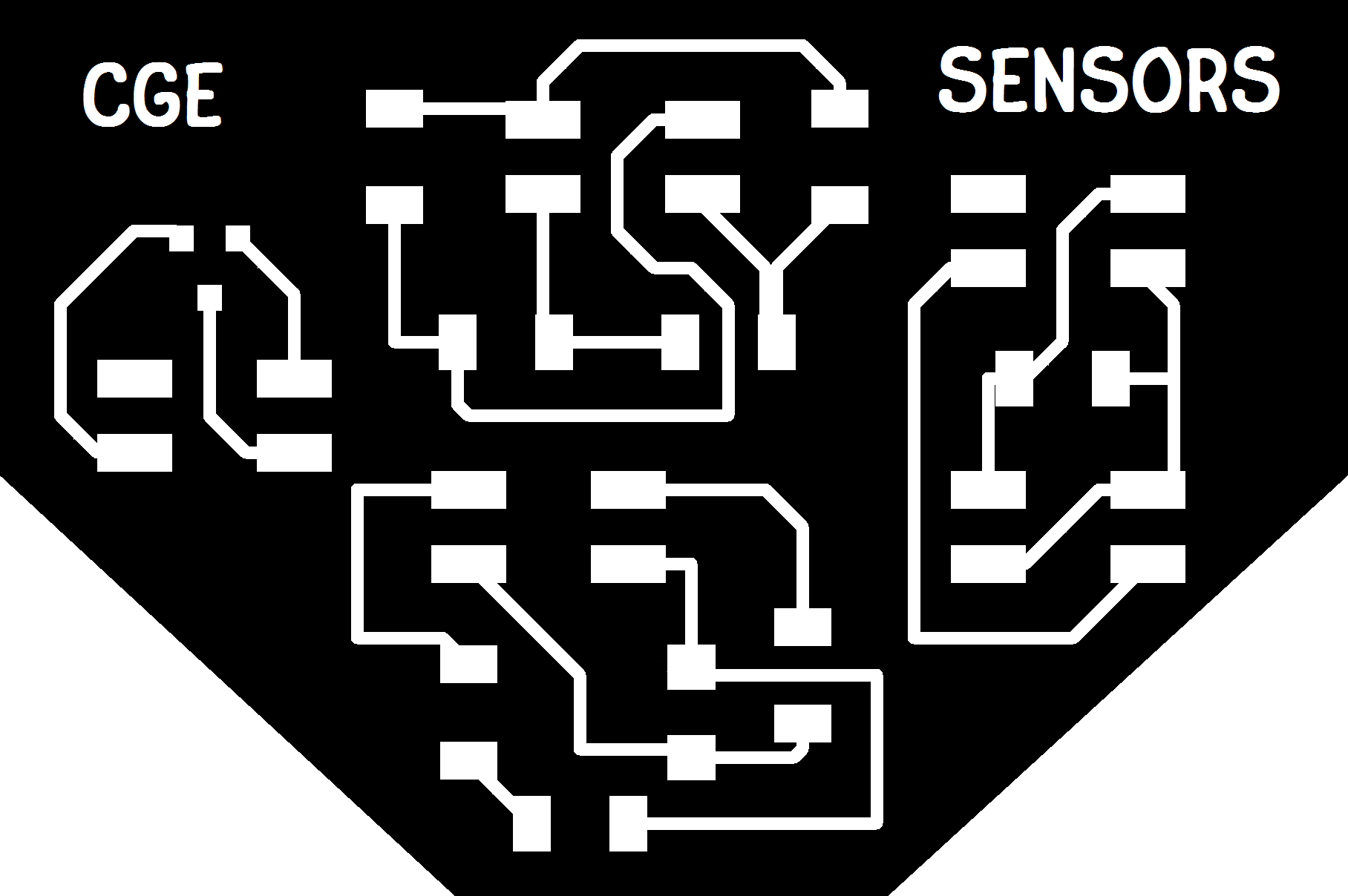
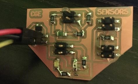
I did fix the board layout which can be seen in proper form here. I think the sensor board is fine. I won't know until I test if but here's what it looks like for now:
Also, starting from Neil's code on button pressing and then reworking it for the pin of interest on my ATTiny 44A to turn and off the LED was successful:
I did make a battery pack as promised but I used the part from the lab which is actually a 9V battery and I didn't realize it and didn't plan for it but I'd need some kind of step down transformation if I can't find a better way to deliver 5V. The AA/AAA batteries are 1.5V, which doesn't go to 5V very well. Meh. The lab is closed. Later--I will have to do it somehow (external power source, maybe not battery pack) for my final project. So it will get done. Probably. Just not tonight. And with all of that I'm going to close for the night since it's 1am. I would like to have tried each sensor and document on it before the end of the semester to do a better job at this week's assignment. A button press is very weak sauce. I wonder what it would take to build an MSP430 replica devboard. I'm just thinking because I think it would help me combine the work I've done in this class with the work I did before. The skills are translating but not as much as I'd hoped with the different environment, idk how to debug without a step by step emulator or register readers. Plus I don't want to print it out but I'm not very good with electronic datasheets. I don't think properly with them and I for some reason never know what I'm reading. Maybe paper is magic. Murphy's Law says I'll get called on to present tomorrow morning but I'll try to see what I can get done in the morning. Oh and almost forgot but pinout diagrams are great and this is the one for the ATTiny 44A:
![[pinout_attiny44a.PNG]](img/pinout_attiny44a.PNG)
The ADC is page 132 in the datasheet. It says to clear the PRADC in the PRR register. Then write a one to the ADSC bit. Higher than 10k impedance may cause non-negligible delay. I'm at 10k so I'll watch that. Ooh there's an internal temperature sensor. ADCSRA is the ADC status and control register. It's table is below:
![[adcsra.jpg]](img/adcsra_reg.jpg)
ADEN is AD enable (1 is enabled), ADSC is start conversion (1 is start), and there are also some prescalers (the table for selecting prescalers is shown on page 147 of the datasheet). I've copied some of the important ADMUX register information below. I'm using PA2 (pin 1) and PA3 (pin 2). The first table gives an overview of the register.
![[admux.jpg]](img/admux_reg.jpg)
The next table tells you which bits to set to select the voltage reference to be used.
![[table163.jpg]](img/table163.jpg)
This next table shows you how to set the mux bits to get the reading you want for a single input.
![[table164.jpg]](img/table164.jpg)
So for the magnetic sensor and synchronous detector I want MUX[5:0] = 000010. The temperature and step I think use differential. I'll have to check on that. This next table (in two parts) shows you how to set the mux bits to get the reading you want for a differential input.
![[table165a.jpg]](img/table165a.jpg)
![[table165b.jpg]](img/table165b.jpg)
Using differential with PA2 and PA3 is going to require a touch more thought since I'm not sure about gain yet and I'll have to think about which ones should be positive and negative. Not that it really matters I suppose.
If ADLAR (left adjusted) is set I can get an 8-bit precise response from ADCH (higher bits in ADC, as opposed to ADCL lower bits in ADC). It's possible to get 16-bits of precision but I will start with using a single register for now where I can. ADC (the combination of ADCH and ADCL) is the output of the ADC. And now I'm going to have to run to class. Sorry for not planning well, I overextend myself.
Well, I'm just going to go with the equivalent of Neil's settings but for the ATTiny44a. When I first started trying that I was having loads of issues so I eventually realized it must be a bit rate thing so I went to code Neil had written for ATTiny44a serial communication (hello echo) and did a bit of work to get that running just right. That work is documented here. I'm back here with a communicating ATTiny44a to get sensor data to the computer. If it doesn't work at least I have the button. This will also play back into interfaces week since I'll have to display the data somehow (first with Neil's Python files and then with something I'll make up, probably some binary determininant instead of a bar graph that shows when I reach a certain threshold in magnetic field or temperature. Or light, since I can use that later on my final project tertiary spiral.
Oh, I did make the button press octave jump circuit for output devices. That was my own code. I also traced Neil's code back to pure C without all the definitions to keep track of. I've also just messed around with setting pins throughout the semester. So button was my area of focus but I did play a bit with thermistors.
Group Assignments
None.