Electronics Design
4 October 2017 | By Casey Evans
“I wonder if there is anything I can do that other people can’t.”
![[opamp.png]](img/opamp.png)
Op Amp pinout. An operational amplifier is one type of component that can be used in PCB designs.
Assignment
Class Notes
Other People
Zach Cohen extruding concrete. Contour Crafting. Beads with a trowl. Ron Rael prints in clay. Neri Oxman glass printing. Ultimakers. “Bladder mechanism for flow control” -Zach. Great choice of words. Tomas. Sense uses a random dot pattern. Form 2 printer by formlabs in CBA Shop. Don’t leave in alcohol mix for too long or in UV curing for too long. Scanning bigger objects is better for the Sense. Zbrush is good for handling bug CG meshes. Meshlab is great for algorithmic work on meshes (fixing normal and finding holes). Blender has been catching up (not zbrush but it’s alright). It is based on mesh processing. EM skin drag display (tearing and shearing). Coil winder in CBA Shop—variable speed cordless drill also works. Having a flux core. Want low hysteresis. I remember learning about that but I don’t really remember what it is.
I wonder if there is anything I can do that other people can’t.
Jeremy Welburn. Based on Alexa Echo. Capacitive sensing in a drum kit. Keeter wrote Antimony and works at formlabs. He did a cool input project back in the day with capacitive sensing. April Johnson. You can print at different layer sizes and resolution. And speed. Apparently printing more slowly and at higher resolution doesn’t really do much for you. Form you can’t see the lines that make the layers. Very pretty. There are set chess pieces. Objects harder than people. Too much or too little of a background is hard for the Sense. Blimp project. Sensing carbon dioxide. Emily Salvador. 3D scanned different texture heels. Used a turn table. Matte does nice diffuse scattering. OpenSCAD does what Antimony does but Antimony does more. Data flow transformations. [Side note: Lawrence is right – when you’re learning trigonometry it’s the hardest thing but eventually it gets to the point where it’s simple and you wish everything could be like trigonometry. It’s not that any of it is hard or easy, it’s that you need to teach your brain to see the world in that way.] Representing things as volumes rather than areas (patches). Epcot is Epcot, not Ebcot…I never knew. Pepper’s ghost fishtank. It’d be cool is she did a jellyfish that followed your finger! Or Danny Phantom. Rosenberg final project had a pepper’s ghost thing. Train sets are fun. Moog synthesizers have analog modules. Track that plays sounds as it goes over a track. Gary Zhang. Stream of consciousness is good and okay. Great. Digital fabrication is cool. 3D printing is one mode of that. “Shamelessly overhyped.” Lots of things are shamelessly overhyped. Perdurantists-how can philosophy account for things that change. Worm theory. Very interesting. People think so differently here than at the Academy. You would be embarrassed to talk about those things there but here I’m embarrassed to talk about what would be cool there. Weird. Gershenfelt Artillect Gilles Azzaro. Cool print of sound. Amanda Ghassaei. 3D printing and laser cutting records. Super cool. Destructively scanning bread. ImageJ to reconstruct bread. Fab modules .vol marching cubes. Under input format. Agnes Cameron. Adversarial interaction on index.html. I should ask Shireen for bread recipes. Bread is good. MATLAB nah, matplotlib is “lovely, a pleasure to use.” Jake Read. This is the kid who did the webpage early. Used NextEngine but switched to Sense, which was “better because it was worse.” 3D scanning is aspirational, it’s not tomography. “What you get is not unrelated to the object.” Jake has a great progression of scans. I wonder if I should try to incorporate my Lincoln work into this class. It would be more cool, but I also don’t know about tying things together that are doing just fine separately. Double win could also be a double loss. FDM printers are not perfect, it’s just squishing beads. Optical photogrammetry. Jordan Kennedy. Goldfish racetrack. Beaver dams. Thesis work. 1000 pictures per site. avconv can make video into pictures or pictures into video. Neat. Agisoft is more serious photogrammetry software. ReCap with Autodesk. Alexandre did chainmail stuff. Fantastically interesting. Nervous system Davis Square. Kinematics dress. The dress I saw in Fresno with Nate. The Nervous system thing is very cool. It stuffs the dress into the printer. Lulzbot Taz 4 with ninja flex material. Generic FDM. Ultimater works or it doesn’t. I may try to scan a person in a posture. Hire Allie and Jon (for free). Then I could test the theory that people are easier than objects. Plasticine. CBA shop has an optimized distance for the Sense. EDS should talk with them to get one. Stag head. Our class is so cool.
This Week
Documenting but being efficient is okay. Notifications check. I get some but not all notifications. I may need to check again. Don’t come in late (ie 5 min after class). Unique recitations to group this week. It will be electronics debugging. I will go because I may contribute to the discussion, or maybe I’ll learn something. Final exam will be Tuesday 1330-1630 (presentations of final projects and weekly projects). If we need to reschedule, figure that out quickly. Bring show and tell from now on.
Designing electronics. Molding and casting is the inverse of 3D printing. Digikey->avr processors->Microchip Technology->SOT-23-6 package. Crystal helps with timing. FTDI header. Pull up resistor to tell it to run when it’s not connected to the programmer. Chip in cable doing serial to USB conversion. Button – in. LED – light out. Maybe a buzzer? And LED for the metronome! Boot loaders are a thing but I don’t understand them.
Components and drawing tools. MAS.862. Check out fab lab inventory. Buttons have four pads but you only need one from each side. Limit current, set time scales and charging times} resistors. Capacitors. C=Q/V. CdV=I. Supercapacitors (10F) between capacitors and batteries. Crystals and resonators. Crystals require external capacitors. They set the tick. Inductors are for filtering. Diodes. Anode->cathode current flow. Current voltage diagram. Generates power in positive voltage negative current. Zener diodes has a drop in the negative voltages. Clamps voltages. Tunneling. Ten cent MOSFETs. “Gate voltage controls drain to source resistance.” Big resistance is big power dissipation. Switching loads of current all the way on and all the way off. MOSFETs only consume power while switching, BJTs always consume power. BJT power dissipation from voltage drop, MOSFET power dissipation from rds. Regulators have output capacitors. Input capacitors can be used for buffering. Zeners for logic levels, regulators use a control loop. OPAMPS, low noise fast slew rates. Built into microcontrollers. ATTiny44 microcontroller ($1). Check out data sheet. Flashbacks to 281 and 382 (courses at USAFA). The Art of Electronics is apparently great. Kirchoff’s laws.
Now on to knowing about footprints in a software (gotta know your package). Fritzing I think is what I used in 382. VHDL for the win! SPICE is also great (Multisim). Tweak the footprint for the machine may be better than tweaking the design for the machine. Thick traces on vinyl cutter, thin traces on endmill. 1/64th is typical. Delaminates around 5/1000ths of an inch. You can also lie and tell it you’re using a slightly smaller tool. It should still work. Routing often collaborative—autorouter plus person. Placing of components can hugely impact how hard it is to route (why I never finished my first PCB design in undergrad). Can try cutting things out and moving them around (like interior design). Raphael Schaad made a hand sketch version. Producing art to machine. Vinyl layers. Fun fact: learning to do things the hard way for a while means the tools are that much more meaningful when you get there. Maybe make the metronome music note shaped. He agrees fritzing sucks. Yay. Eagle is by Autodesk. It’s apparently great. Eagle on Fusion. Maybe design the circuit in software and then add the artsy stuff in paint or something. Eagle is a structured workflow. But worth the effort because of the hierarchical design. DesignSpark and MultiSIM Blue are tied to parts (they’re also distributers). KiCAD open source and powerful but it’s a bunch of programs poorly stuck together. Altium is fairly high end. Circuit Maker is their community version. OrCAD powerful PCB tool, part of Cadence (high end IC design). LTspice is free. VHDL and Verilog – programming languages for circuits. Sam Calish. Mods has a pretty cool interface. I’m not sure it works on Windows though. I should ask for clarification on measuring operation versus testing operation. Xtal = crystal. Resistor in series with LED to limit current. 1kohm is typical since we expect 5V. 5-10mA in the LEDs is normal. Arrow to ground because of LED direction. Pull up on the switch or just know that the processor has built in pull up resistors. If you don’t use a pull up the logic will just be floating. We’re supposed to practice soldering again. Measuring is oscilloscope or multimeter stuff. Test is seeing if it talks. Simulating should be easy enough so I’m going to try that if I can download Multisim.
Training Summary
go to this page, copy fab.lbr somewhere, right click->new->schematic, the board is here: link, add ATTiny SOIC, add ISPSMC, net, right click for diagonals, switch to board, route/ripup, 1mil-25micron, adjust boundaries, layers, select none then only select top, file, export, image, check monochrome, 1000 dpi, rect, select bottom as layer, draw it, select only bottom layer, file, export, image, check monochrome, 1000 dpi
Assignments
Individual Assignments
Traditionally, I've always designed, done the maths, sim'd, built, then tested. This week isn't as clear but I will probably design, build, sim, do some maths and then test (after I finish building). I've always used Multisim for simulation but MIT doesn't have a school license (weird because USAFA, a much smaller school, did). Anyways, Multisim has this not very functional beta version of a browser simulator here. I got a 7 day trial of the real thing but I don't want to use it till I'm actually testing my board, just in case I need to redesign. I've also never used Multisim for premade parts like this before. I just did filters, transistor circuits and power electronics. I'm not even sure they have all the parts. I think to start then I will use the browser to model the two "design" parts to the week: the button and the LED. Or, well, just the LED I guess. Below is the sim for a 5V voltage high from the pin onto an LED and current limiting resistor. I chose a 1kohm resistor because with Ohm's law (V=IR) a 1kohm resistor will limit the current to about 5mA, which is well within the peak current limit of 200mA and the 100mW peak power (5mA*1.7V=8.5mW) given a 1.7V forward voltage.
![[simple_sim.PNG]](img/simple_sim.PNG)
From the sim you can see that it estimates a current of 4.3mA using a virtual LED. You can also see that it uses the 0.7V diode approximation. Forward voltage is not a parameter in editing the virtual LED model, otherwise I would improve the simulation by matching it more closely with the datasheet (and the diode itself after measuring its properties). But the exact resistance isn't necessary for the PCB manufacture. So I started working in Eagle because I got back from my lab a bit late and wanted to try to get the board milled ASAP. I have a soldering iron at home but no milling machine and I thought the EDS lab closed at 20h. They were kind enough to stay open until 21h but my board was still milling then. So spoiler alert, I didn't finish. Eagle is pretty great. I forgot to set the grid and trace width early on so I had to go back and adjust for that a bit later. I still don't think it was perfect though. I will have to see when I inspect my board after it gets out of the mill. The final trace diagram is below
![[light_traces.PNG]](img/light_traces.PNG)
Behold the rather unhelpful schematic:
![[schematic.PNG]](img/schematic.PNG)
After starting to mill that last trace I realized it would be better to put the current limiting resistor before the switch (more on that here). So I redid the design to look like this instead:
And here is a more intuitive schematic version of the design:
![[better_schematic.PNG]](img/better_schematic.PNG)
When I tried to mill I had issues since it didn't want to print deep enough.
![[bad_depth.jpg]](img/bad_depth.jpg)
After a few tries adjusting cut depth to 0.0045" and then 0.005" I eventually got a good cut. But that was when the lab closed. You can tell it's good because of the white dust coming up.
![[good_depth.jpg]](img/good_depth.jpg)
So what's left is to cut out the last trace, start the new design trace, cut that out, solder the board, program, test and measure results. Since I'm not entirely sure how the programming part works I'm going to have to talk to Gavin or Alexandre (who I know already programmed his--I think). I've only ever worked in code composer or VHDL. I don't know how else to load programs except to tell a GUI to do it for me. But, yeah. Time to look at the datasheet for the ATTiny. Here is a link. Brings back some memories. I'm pretty confident I could write some test code for it (turn the LED on/sound the buzzer based on a button press) but I would want someone to walk me through the programming steps. I'm incluned to believe that I'll need the chip I designed last week but I'm not sure how that all works and it's usually better to ask someone who has figured it out then to dig around in the dark forever and have the anticlimatic realization that it's not as challenging as it seemed. And I need to build it first. Mostly because I really prefer testing code incrementally. I'll probably use Neil's code as a baseline structure for my code. Not sure what I'll need to change yet, I haven't really looked into it. Goals.
So something happened to my board. I don't rembember what but the last one didn't actually work for some reason. So I had to try again. Oh wait, I remember. I changed the design to add the switch and the buzzer. And of course I had lp0 to lp1…drama. Now it’s printing, which is a great step towards actually finishing this. To help me remember in the future I will document: open the mod server command prompt, open the web browser, select open new server program, select the png file of interest, ensure the dpi is at the same setting you exported from Eagle at (for me this was 1000), hit mill traces, hit calculate, check that the device is /dev/usb/lp1 (for the particular setup in EDS), move the origin to where you want it, set the end mill, hit calculate again, send file to device. Also vacuum, because that is a good thing to do. Having just a black image doesn’t make an outline happen. You have to at least get a white outline around that. White is high, black is low. I think it cuts around white on the black surface. Which may be slightly problematic for my chip. The speaker can do 0.25W or 250mW. P=IV=I^2R=5mA^2*8ohms = 200uW. This is a very safe operation. Max current would be sqrt(0.25/8)=177mA. I tried to add a hole in the corner for like a keychain ring or something just to see what would happen but since it did the outline first it just popped the board out, which was convenient but something to look out for in the future.
![[pop_board.jpg]](img/pop_board.jpg)
It was undamaged though:
![[no_comp.jpg]](img/no_comp.jpg)
I tried to take off the excess copper in some areas, even setting up a surgical mask thing, but it ended up still not being worth it since I kept scratching other areas.
![[surgery.jpg]](img/surgery.jpg)
I had to take a razor to the switch to get it to sit comfortably on the surface of my board.
I added the buzzer with wires leading off the board:
![[board_n_buzzer.jpg]](img/board_n_buzzer.jpg)
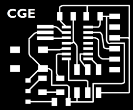
Then I bent those wires back and attached the buzzer to the back of the board. Looks pretty great.
![[cge_board.jpg]](img/cge_board.jpg)
Since this fab I tested VCC to be 5V, ground to be 0V, both configurations of the switch (the toggle ends up between the two nodes that are connected and the middle node is the input). We'll see how voltage levels stay after programming.
I programmed the board for the first time in week 7. All my other embedded work builds off of this board. I used the speaker and LED and button in week 9 and week 7 as well as incorporating it into my final project. I finally got hello echo to work in week 12. I did some work with sensors, the button and this board in week 11.
As an after thought - I am very comfortable with analog circuits (in week 13 I made a opamp/voltage divider circuit. So throughout the semester I mostly just tried integrating hello boards and adding things to them (like pins and sensors). I stuck with the ATTiny 44a because I like using minimal resources and dislike having things I don't use. But I feel confident that I could step up to a more powerful microcontroller if I wanted/needed to. As is the hello boards are very basic in form - there's not much you would change about them when using them in a circuit (for example I combined a bunch of sensor hellos in the input devices week). Anyways, I think I would like to go back and do more EE work with boards I mill myself. It would be fun.
Group Assignments
None.