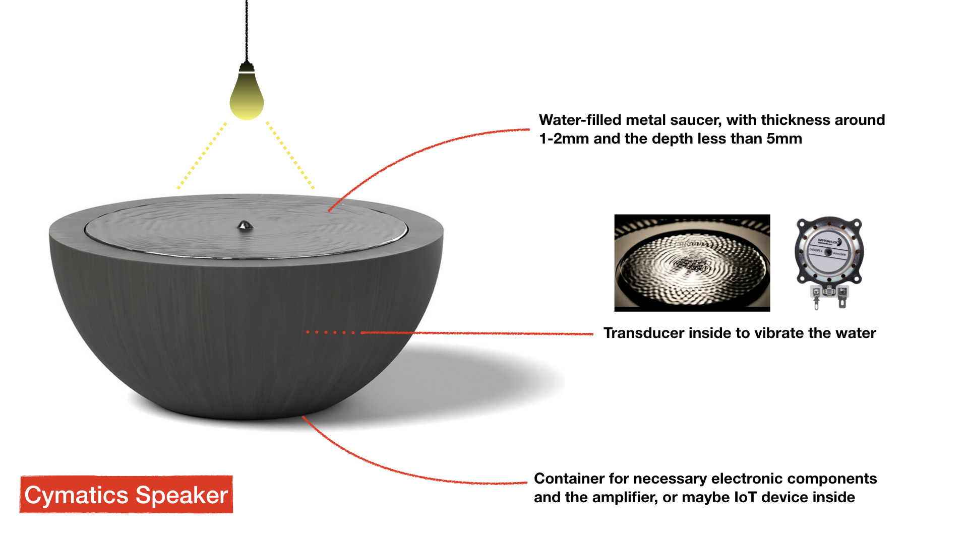
As you can see in Week1, my initial proposal is to create a cymatic wireless speaker that functions as an IoT device. I don't have experience in any visual and product design, so I limited the proposal on a more reasonable scale to make it come true. I wish I could build up a device that incorporates digital fabrications, electronic circuits, input/output components, and customized programs to implement the interaction with the computer-aids design process.
What I actually have for the final
The concept for my final product is to have a generative music device that creates the background atmosphere. This project aims to create an endless and evolving background soundscape with repetitions, unpredictabilities, and randomness. The software itself is the composition. The melody consists of the purest form of a sound-sine wave. The music happens when the ultrasonic sensor detects that there is someone in front of the device, and then continually evolving under the prepared rules.
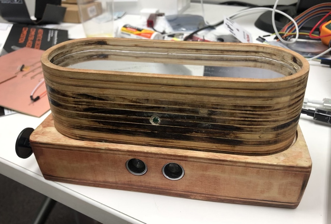
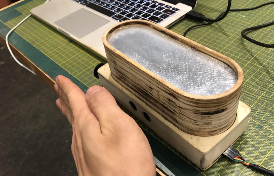
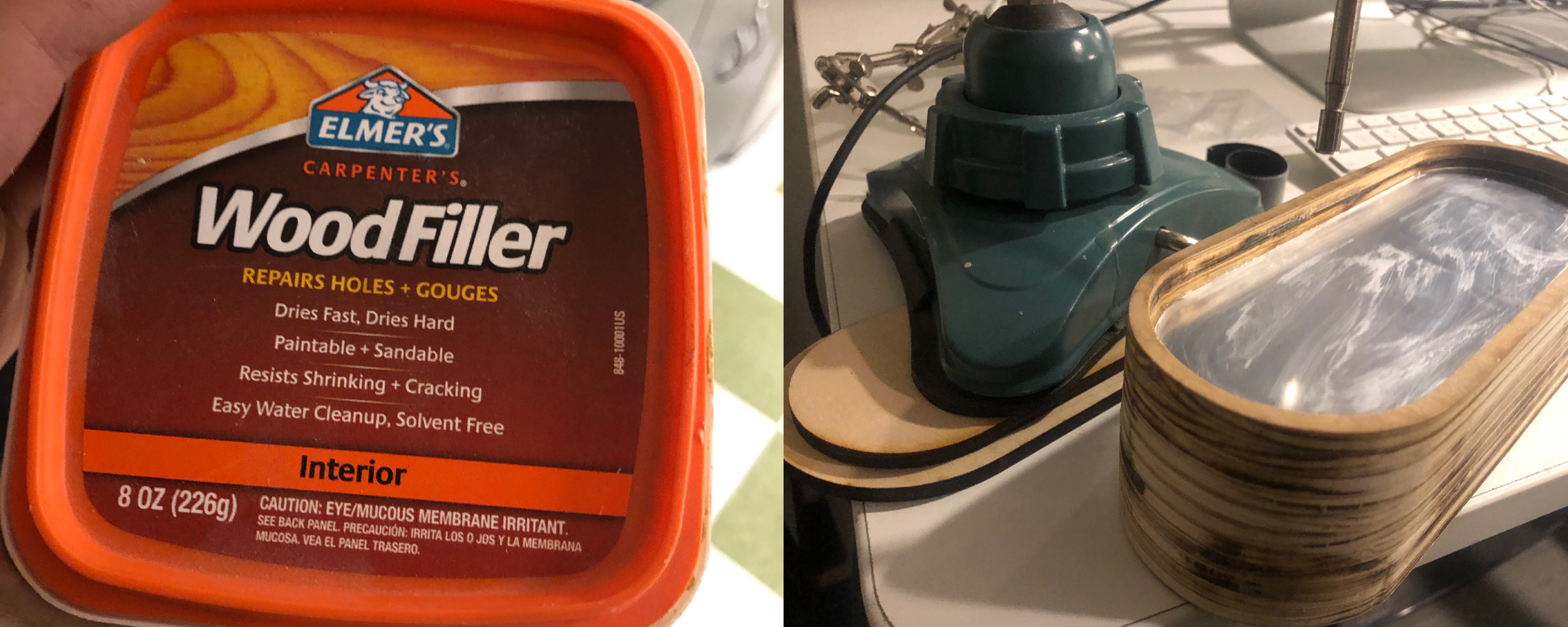
I was planning to make a small prototype before the final product. But in the end, I could barely finish the demo version with minimum functions. The laser-cut plywood is not the best choice for holding water, but the appearance looks good after sanding.
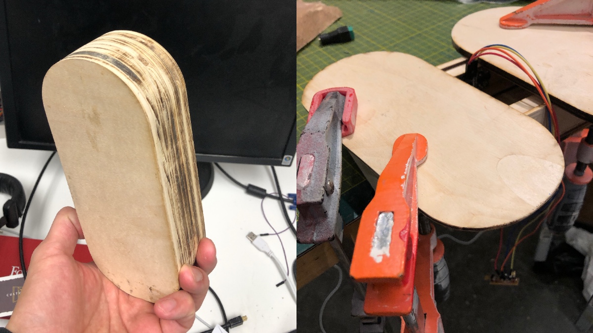
The procedure of making the container.
There are two transducers attached beneath the surface. I tested several combinations to get better performance. The water patterns appeared when the vibrating frequency corresponds to the resonant frequencies of the material.
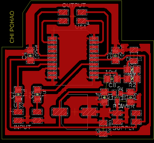
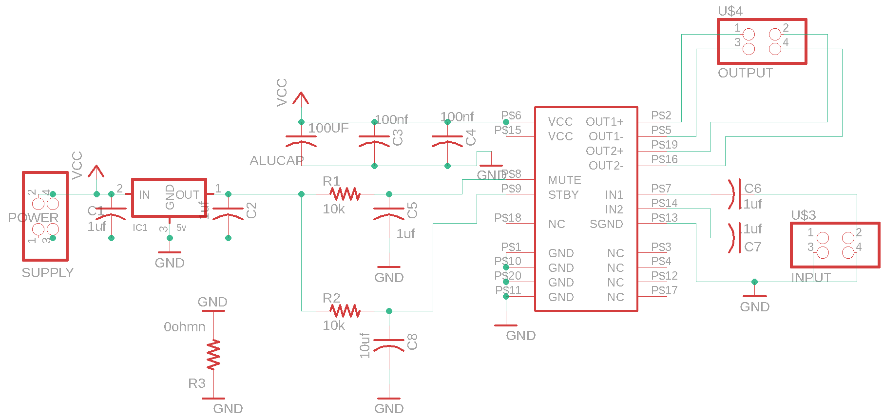
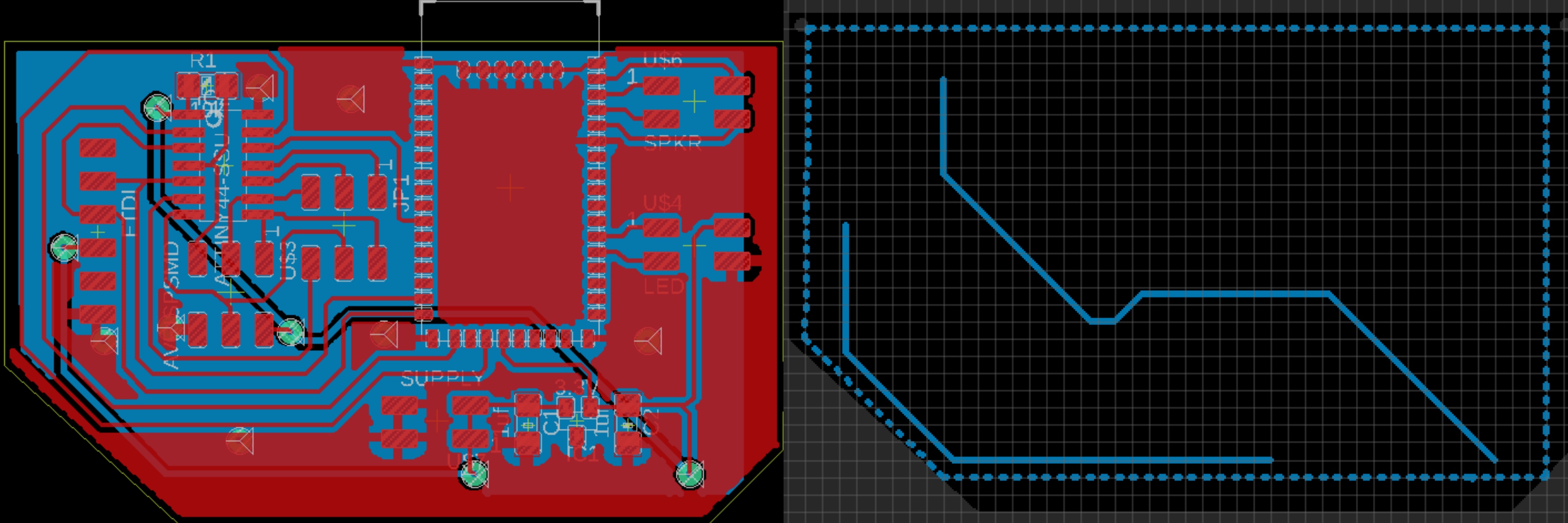
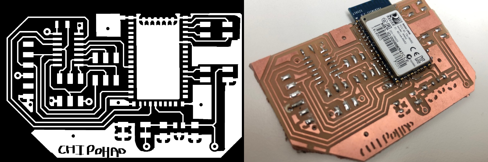
There are three separate boards inside the container, the amplifier, the Bluetooth, and the sensor. I designed the PCB layouts in Eagles. For the stereo amplifier board, I used a TDA7297 amp module. The TDA7297 is a dual bridge amplifier specially designed for TV and Portable Radio applications. It has 6V-18V supply voltage range and stand-by & mute functions. Here is the diagram. For the Bluetooth audio, I used the RN52 module, which has built-in controller commands and state indicators.
The TDA7297 amplifier board and schematic
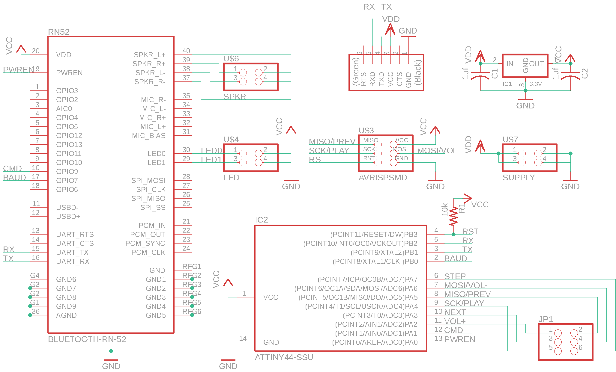
The RN52 Bluetooth board and schematic
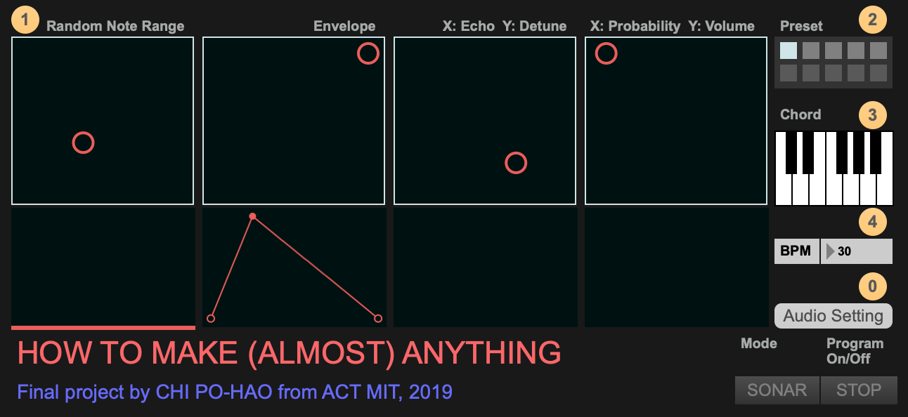
I developed the program that generates music in Max 8 (from Cycling'74 company). There is an adjustable note scaler, mode switch, and start toggle on the right side. The XY-pad interfaces control various parameters, including note range, amplitude envelope, detune and echo, volume, and probability. The probability and volume parameters are controlled by the distance and period detected by the ultrasonic sensor.
In edit mode in Max, you can see how I control the note range and distribution with the table object.
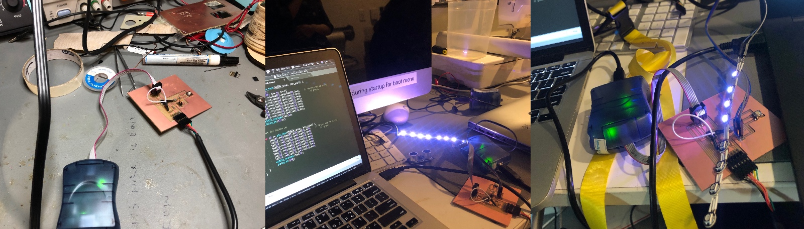
After finishing the program, I connect the ultrasonic sensor with FTDI cable as a serial input and scale it in the Max. I need to split the numbers in a readable range and filter out the noise and unwanted numbers. I did several tests to see how my program react to the sensor value.
I did a quick test after I successfully installed electronic components inside the container. You can see the cymatic effect of water pattern that controlled by the distance of my hand in the video.
Unfortunately, when I tried to install the light components on the system, I broke the PCB and couldn't fix it on time. I will try to fix it during the week after the finals.
The Failed Attempts & What has worked and what hasn't?
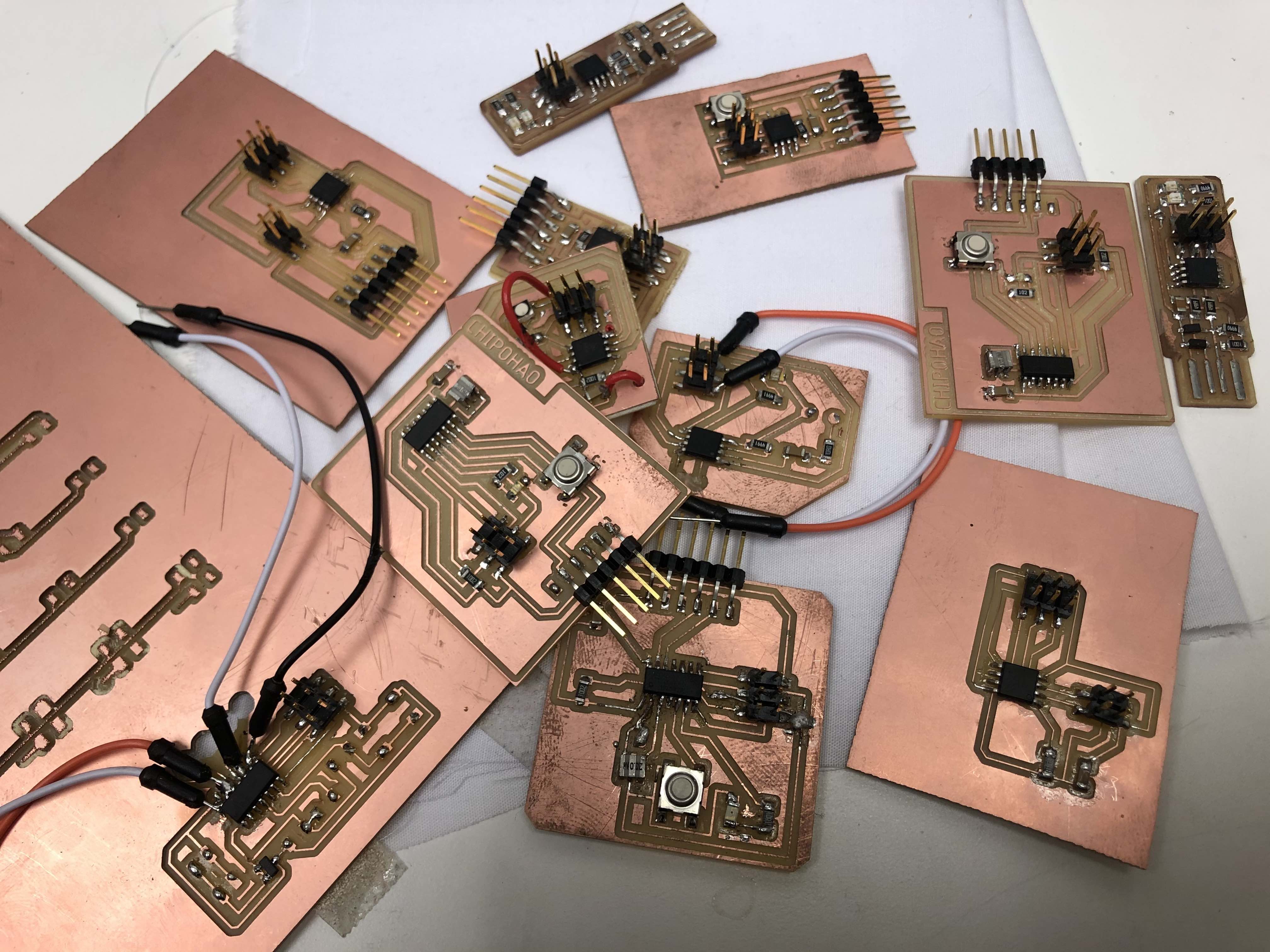
The whole process of learning electronic design is miserable. I kept making new boards but lack of ability to tell what was wrong in the electronics. The picture below is just a small part of my failed board. I think the better is to make a power board with enough GPIO pin and function similar to an Arduino so that I can test different input and output devices without milling a new PCB.
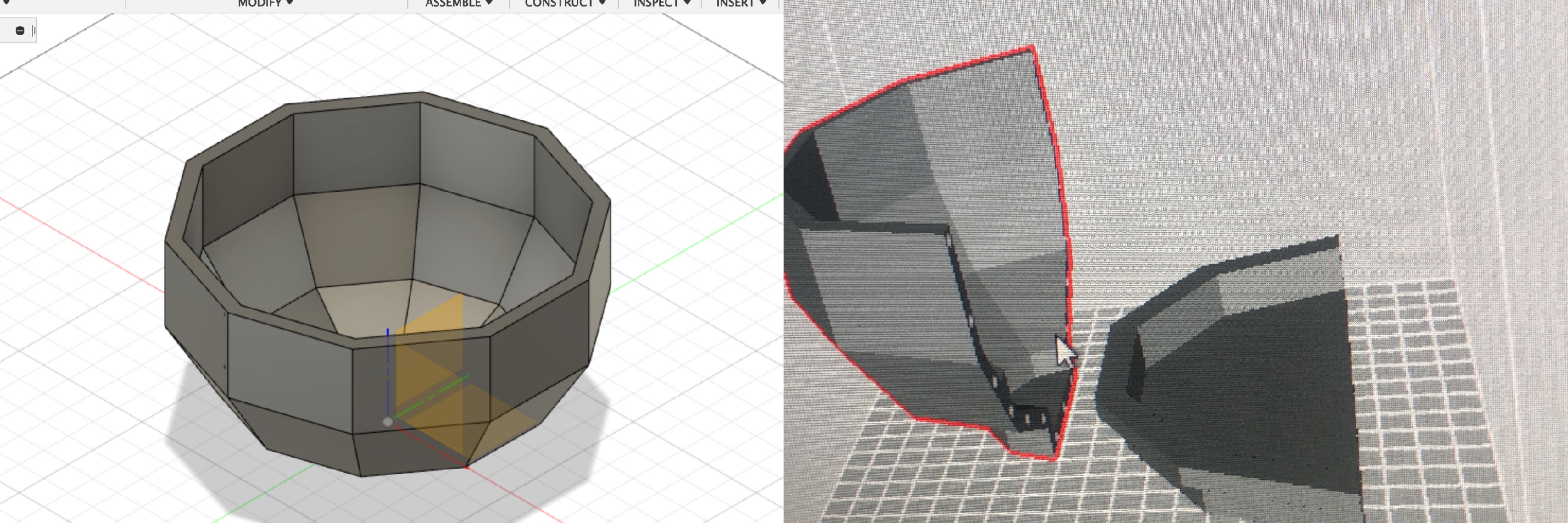
In the very beginning, my funal's container design was similar to the original concept demonstration image. Firstly, I drew in Fusion360 software, and 3D printed the parts evenly with the joints. But due to the errors during printing, the pieces cannot perfectly match.
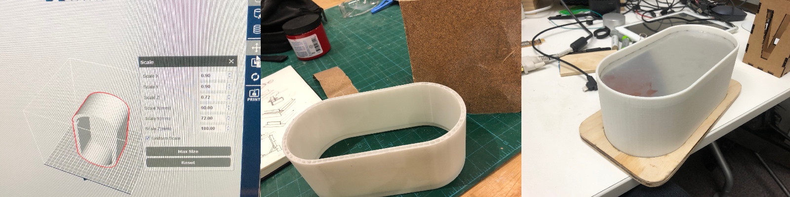
I modified the design and tried to print the whole thing and then used plaster to do molding and casting. Unfortunately, I couldn't demold because I don't know that I need to apply a layer of mold releasing agent first before pouring the plaster. And then, when I was working on the prototype, I made another design that is larger than the prototype to make it easier to install all the electronic components. I supposed to do molding and casting after 3D printing to make the new container have the elasticity to absorb the vibration, but I had no time to finish it due to my inefficient workflow.
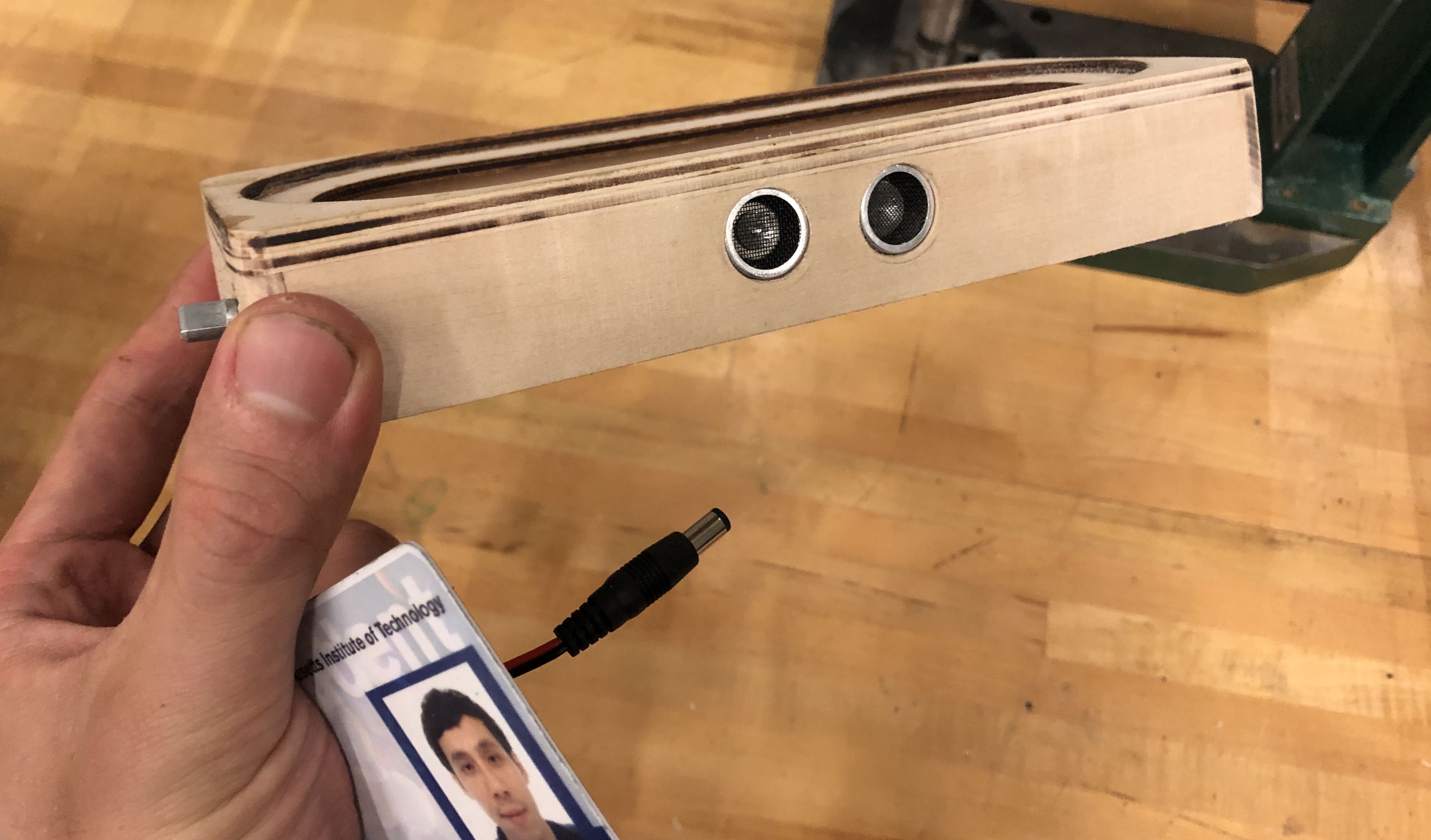
The prototype became my final product for this course. The chellenges waere to make everything inside the small container and drill holes for the control interface, power socket and wires to install on the container.
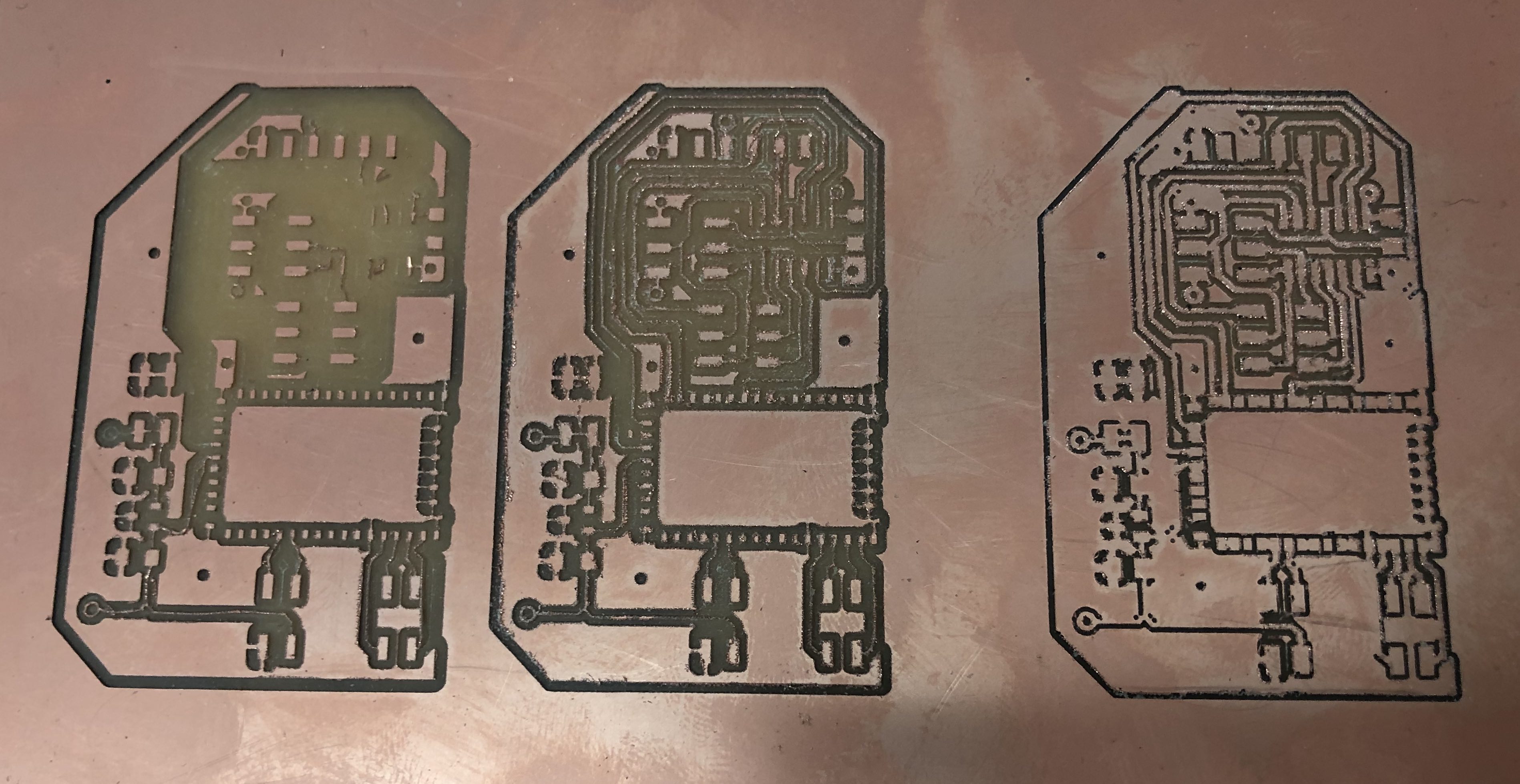
There is a crucial problem I encountered when making PCBs for the final project- the Mods couldn't read my Eagle-exported PNG file. Since the PNG files exported from a Mac system have a double resolution, we need to double the resolution value in Mods to get the correct size. Otherwise, the Mods interface will ignore the path and not cut through the gap between the original footprint. I tried to adjust the parameters and routing in the Mods (and learned a little bit more about it) but ended up wasting time and got numerous failed boards.
There were not so many problems during the first few weeks since the boards made at that time were not that complicated. Still, for a more complex design, or design with several layers, the image processing in Mods made me felt hopeless, and there is no tutorial and documentation that I can follow. I spent hours in Mods trying to get it to work and manually edited in other software like Adobe Photoshop (But I couldn't keep the image dimension after exporting). Thus, the whole working flow became very inefficient and hard to adjust. Overall, I used GIMP to manually increase the space between footprints and kept the same dimension of the images. And finally, I could mill and soldered the RN52 module on the milled PCB.
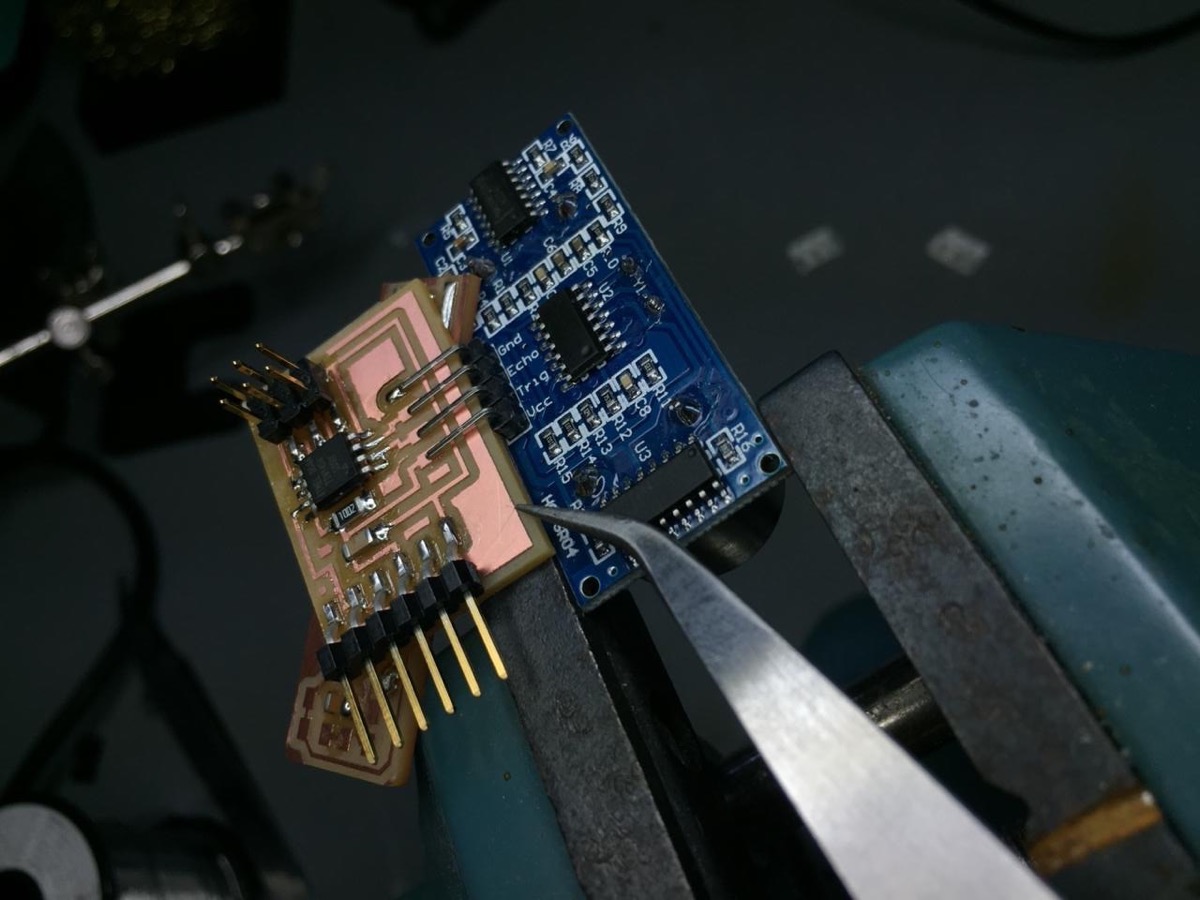
The failed board I made for controlling the light with ultrasonic sensor.
The Bluetooth and amplifier board, the cymatic effect, and the generative music system work fine in the end. But the wireless communication for the sensor failed. I couldn't figure out how to use the RN52 Bluetooth module to transmit the sound and receiving the data from the ultrasonic sensor through the serial port at the same time. For the amplifier board, I waited for a while to receive the capacitor I need (100uF 16V AL CAP). The image below is the finished amp board and its diagram.
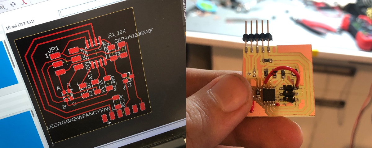
I wanted to use the input device to affect the output device. The original idea is that the value of the distance send out from the ultrasonic sensor should affect not only the sound but also the light. I designed several output devices and used the connector to communicate with each other, but all of them didn't work.
My tiny jump wires on the tiny board.
After searching and looking back to the previous week's HTMAA pages, I realized that I misused the MISO and MOSI, and I shouldn't use ATTiny45 but other ATMEL chips that provide more GPIO pins.
Sadly, even though I soldered the jump wires, the PCB board was still not working at all. After helping my ACT classmates, I felt that I should skip this step due to the limited time. I switched to consolidating all the necessary parts to make the final product functional and useable.
I helped Emma's project with Adafruit's NEOPixel LED array. The format of MAKEFILE from Adafruit is different from Neil's, so I spent some time to test and write the loop function with the button trigger.
Downloaded and modified files with my laptop to program and test the NEOPixel array.
What Have I Learned?
As an amateur and beginner, I should start working on the electronic design before the fabrication parts. In the end, I have no time to remake the board event though I understood what mistakes I made on my board. The workflow and schedule are essentials for implementing a project. And for things that you are not familiar with, it would be a good idea if you order and test them as early as possible. Otherwise, you have no time to adjust the design.
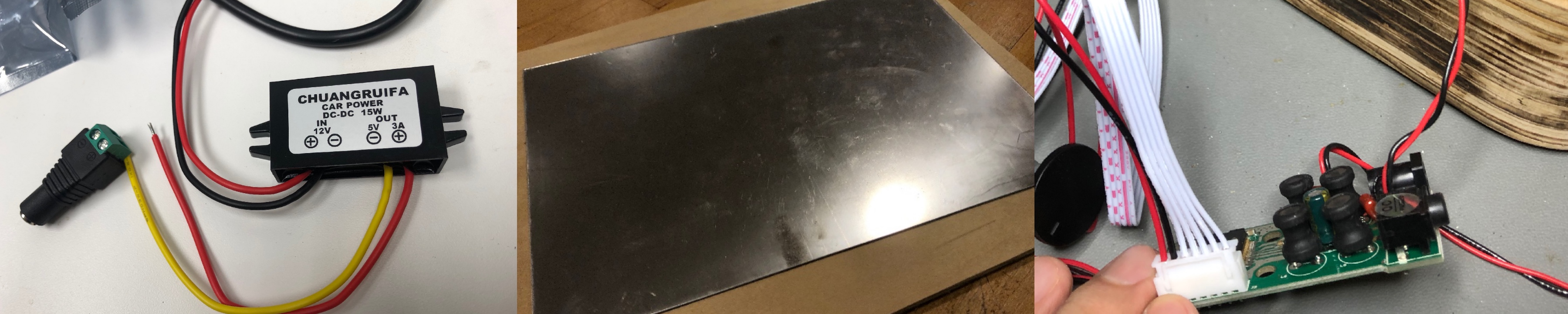
The 12 to 5V converter, mirror paper for reflecting light, and the amp module I used before I recieved the needed capacitor.
I have learned the basic manipulation and concepts for the PCB and AVR design. For example, using "ratsnest" to make the cooper layer as the ground, using the "ripup" command to reverse, using DRC to change the rules, and the function of different layers in Eagle. I also learned how to fill a hole in woodwork.
I should not waste too much time in milling the PCB boards. The main problem is that the PNG file, whether I use the python code or directly export from Eagles, the Mac system exported twice the resolution than Windows. It caused problems for Mods to process the images.
During the last week working on the final project, I finally learned the basic concept of AVR programming. I wish I could have some experience in C code so that I can explore and play with all the material we have in the CBA shop. Below is the short documentation about the AVR programming for an LED array that I did in less than 30 minutes of exploration. It was a simple task, but this couldn't be done if I had never taken this course.
For the digital fabrication part, I learned how design is crucial in the process. I kept making mistakes like the wrong position and size for holes, the order of steps, the routing of wires, which made me need to remedy in situations that difficult to work smoothly. I hope to be an TA next year to better incorporate skills I learned this semester.