Week8Molding & Casting
This week we worked on molding and casting, and the assignments were reading through the material datasheet and making something afterwards with the materials and milling machine. The while process involves four steps: (1) Design a 3D model, (2) Cut out the positive mold (3) Cast the negative mold with OOMOO (4) Cast the end result with plaster or metal. The training session gave us a comprehensive demonstration for each part and introduced the metal melter and the vacuum for mixed OOMOO.
3D Modeling
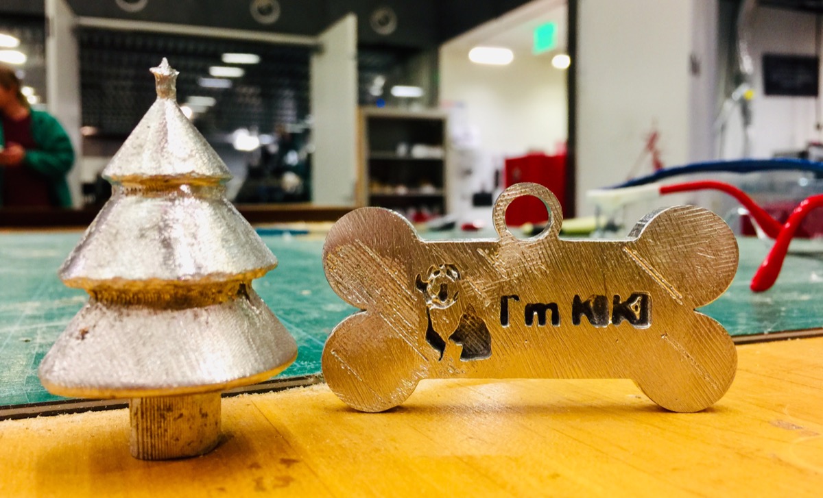
I made several prototyping designs, such as a dog tag and a Christmas tree in Fusion360. I imported it into PartWork3D to export the toolpath file for desktop ShopBot to mill the wax.

The wax brick should be fixed on a wood panel with glue and screwed on the milling machine surface. This part is similar what we have done in the week of CNC machine.
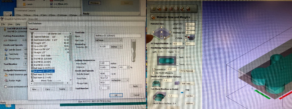
There are few things need be aware: (1)choose the correct mill type. (2)select the left-bottom corner as the original point. Most of suggested parameters can be found in the document that Tom put in the computer for desktop Shotbot.
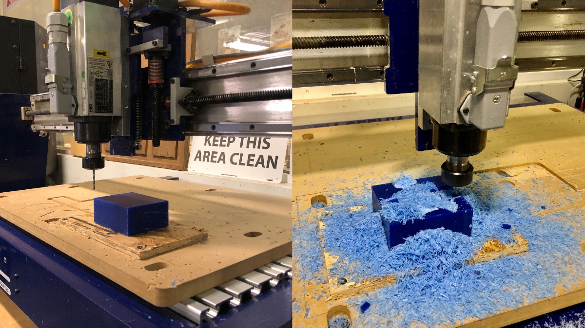
The machine actually did great jobs in milling wax.

Molding and Casting
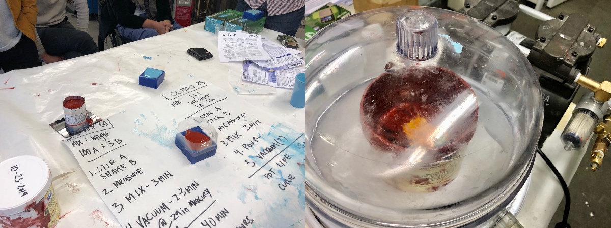
Followed the instruction and datasheet to integrate necessary materials. By pouring part A into part B, mixing it up, vacuuming the bubbles, and pouring the OOMOO into the mold, you can simply get the negative mold for casting.

You can see my casting result with the plaster(Hydrostone).
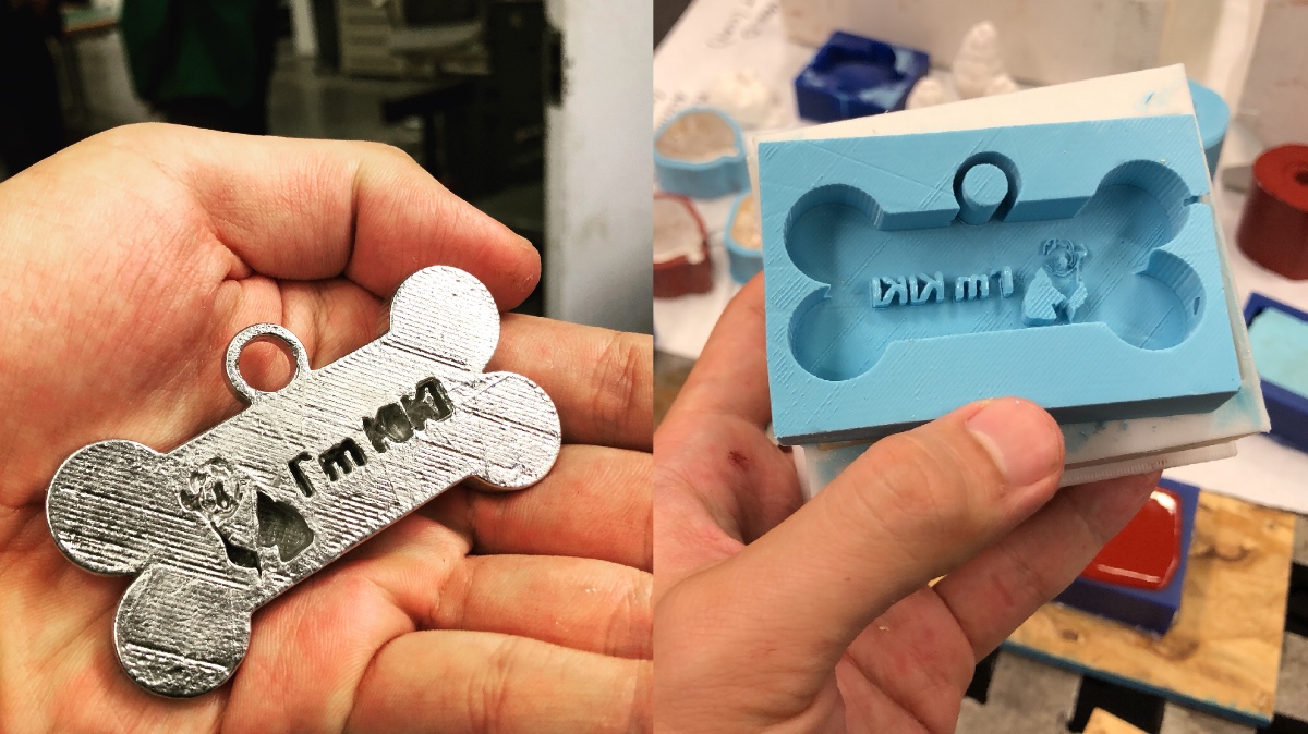
I also tried metal casting by melting the tin piece and carefully pour. It was a really fun week.

Week9Input Devices
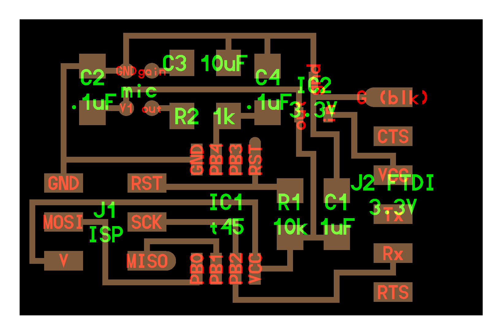
This week we focused on input devices for receiving the variations from the environment. I tried to add a MEMS(Microelectromechanical systems), which is a tiny microphone component that being widely used in our mobile devices and smart speakers, on the PCB board to run through the whole process.
Now we are more familiar with each step for electronic productions. Since it often takes a long time to use an SRM-20 milling machine. I used another milling machine in the electronic studio to mill my board.

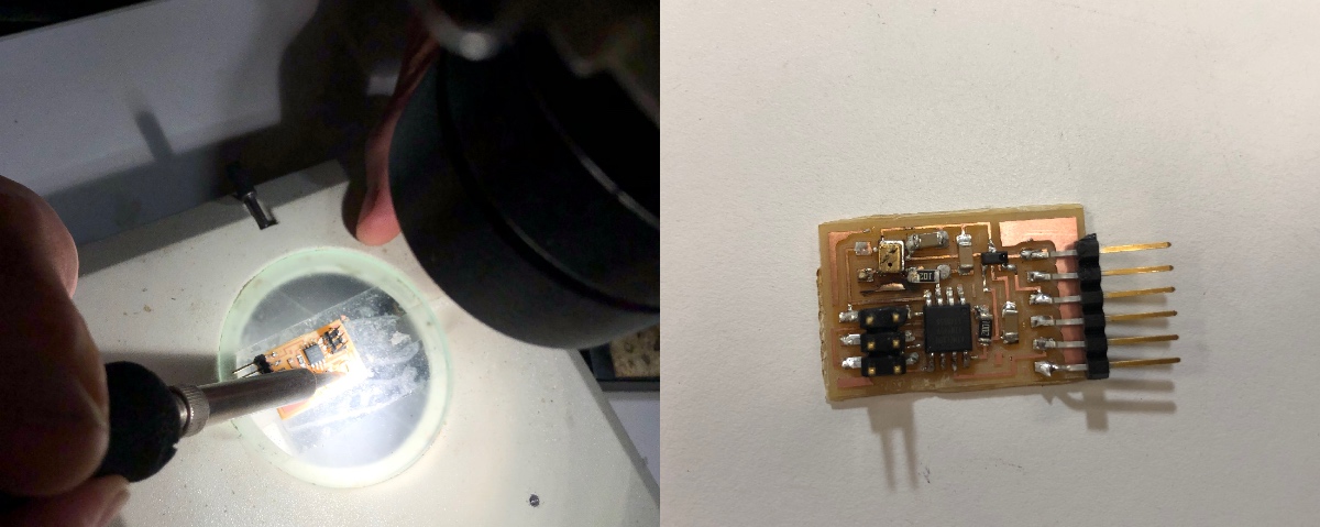
Soldering the MEMS components is such a challenge. I failed several times when I was trying to fix the pins on the coil spots by a soldering gun. In the end, I successfully soldered it by using a microscope and heat gun with some soldering iron attached to the MEMS in advance.
I tried to read through the C code and python code provided on Neil's website. It was a difficult task to me, but now I know a little about the logic, and the reason why it kept counting 1, 2, 3, 4 to be synchronized.
I used AVRSIP MKII and FTDI-to-USB cable to program my MEMS board.
To program the board in the terminal on a Mac, first, you need to indicate the exact USB port with this command to view all available ports on the computer.
ls /dev/tty.usb*
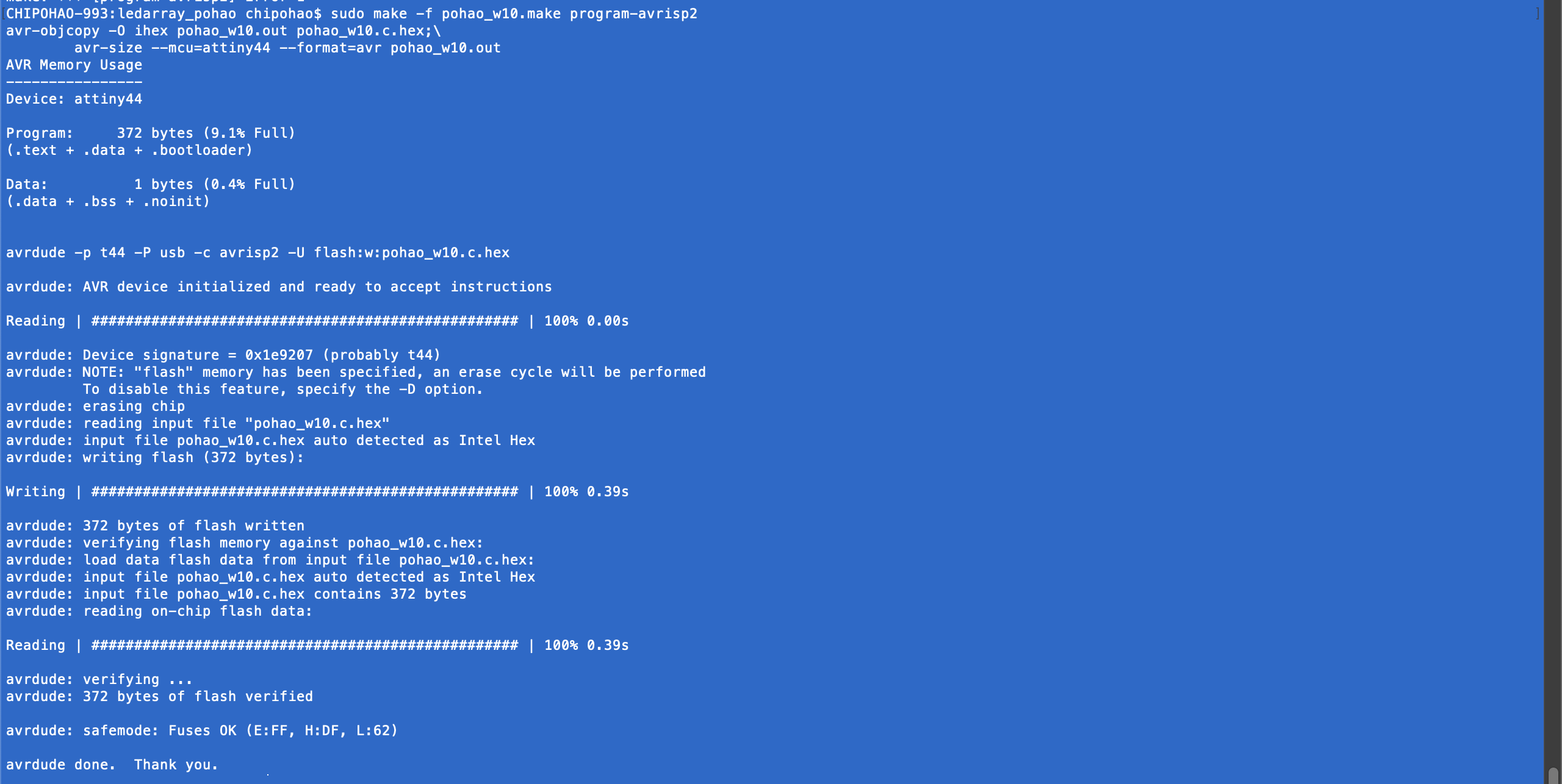
And then run the make file to program it with this command.
sudo make -f hello.HC-SR04.make program-avrisp2
Once the terminal returns positive responses and a finished message, your board is all set and can run the python file to receive the sensor value. The python file that Neil provided on the website functions as a graphical interface to visualize the input data.
python hello.SPU0414HR5H.py /dev/tty.usbserial-FTAV0OC8
Here you can see my result in the short video. I don't know why, but there it seems that there was always a latency between the occurrence of voice and the corresponding movement in the visualized amplitude waveform.
This week I only did a minimum requirement for the assignment, but I helped my ACT classmates to catch up on the embedded programming, so now we can move forward to the final projects!
You can see I redesigned the examples from HTMAA's website, added button and integrated the components in Week10 doucmentation!
Week10Output Devices
This week was very frustrating. I failed again and again. I wanted to make a Charlieplexing LED array that can be controlled with a push-button. I adapted Neil's board to include the push button and a pull-up resistor. I designed the board in Autodesk eagle. Here is my schematic.
I learned that I could use separated GND and VCC parts in the schematic view to make the design more readable in Eagle. Here is my board.

Initially, I want to make the PCB design in two parts. But when I tried to cut out my board, the parts peeled off and was being involved in the spindle. And then I cut another one, but I attached the soldering iron to the board too early and forgot to cover a layer of insulating paper in advance. PCB milled using Roland MDX-20.
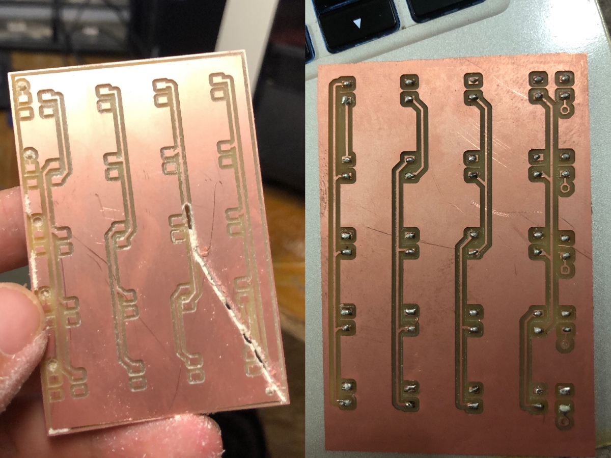
Here is my second round PCB, but it also failed due to some soldering problems. I spent quite a lot of time to figure out the problem but ended up with broken cooper-foils when unsoldering.
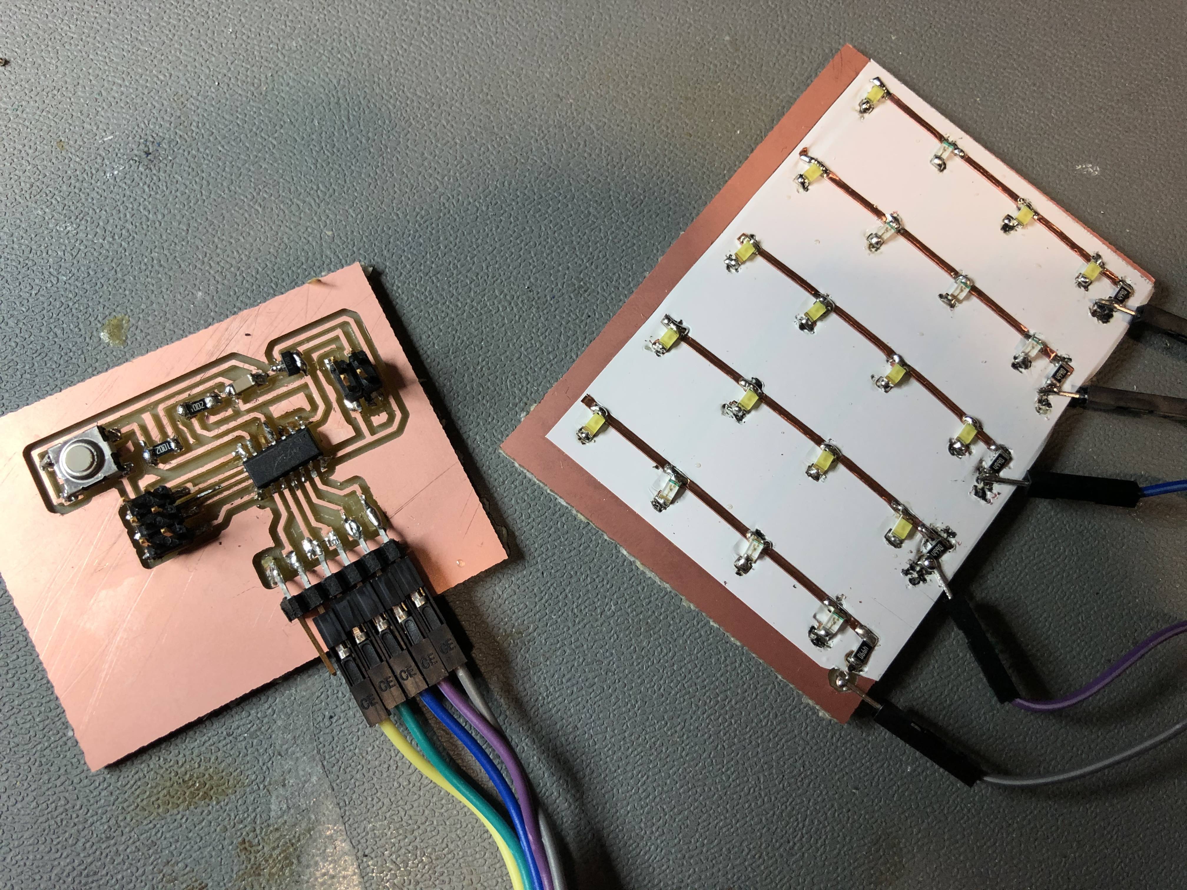
So, my third try as the picture below. I soldered all the components on a huge board.

I changed a little bit of the code to add a push button by typing a line of code below.
#define btn_pin (1 << PA7)
And then, I added an if-else function in the main loop.
while (1) {
          if (PINA & btn_pin){
            led_cycle(0,0);
             }
          else {
            led_cycle(100,1);
            led_cycle(1,100);
             }
          }
The programming part was done by changing the project name in Neil's make file to the name of my C code file. When I press the button, the LED array should start to display patterns of light.
This time it was finally working (partially). The background layer of copper foil caused the short-cut, so only half of the LEDs lit up. You can see my unperfected testing video here.
Week11Networking & Communications
This week's assignment is to design, build, and connect wired or wireless node(s) with network or bus addresses. In the beginning, I was thinking of starting with ESP32, but since I was not in town during the weekend, there was no ESP32 left in the CBA shop when I came back to Cambridge. As a result, I decided to use ESP8266 to try out wireless communication.

I am interested in what the network is and how it works. In "Me++: The Cyborg Self and the Networked City", William J. Mitchell claimed that the networked entities, whether humans or non-humans, creatures or machines, are being embedded everywhere, in every kind of systems. It changed the concept of the "real-world" and dissolved the boundary between cyberspace and meatspace. And Wendy Chun also suggested that "What it means when media moves from the new to the habitual—when our bodies become archives of supposedly obsolescent media, streaming, updating, sharing, saving." in "Updating to Remain the Same." These discussions and hypothesis are all corresponding to the introduction in "Internet Ø: Interdevice Internetworking- End-to-End Modulation for Embedded Networks." from Neil. I am excited about the possibilities of applying these networked systems in artistic practices and plan to explore related topics during my study at MIT.
The ESP8266 family and ESP8266 ESP-12E
ESP8266 is a low-cost RF module produced by the Chinese manufacturer Espressif Systems. It includes a full TCP/IP stack and comes pre-programmed with an AT command set firmware, like old modems: so, you can hook this module up to your Arduino (or hello board) and get WiFi-capabilities. However, the ESP8266 has on-board processing and storage capability (like an Arduino) that allows it to be programmed and extended. Moreover, it has a few GPIOs to which sensors and other interfaces can attach.
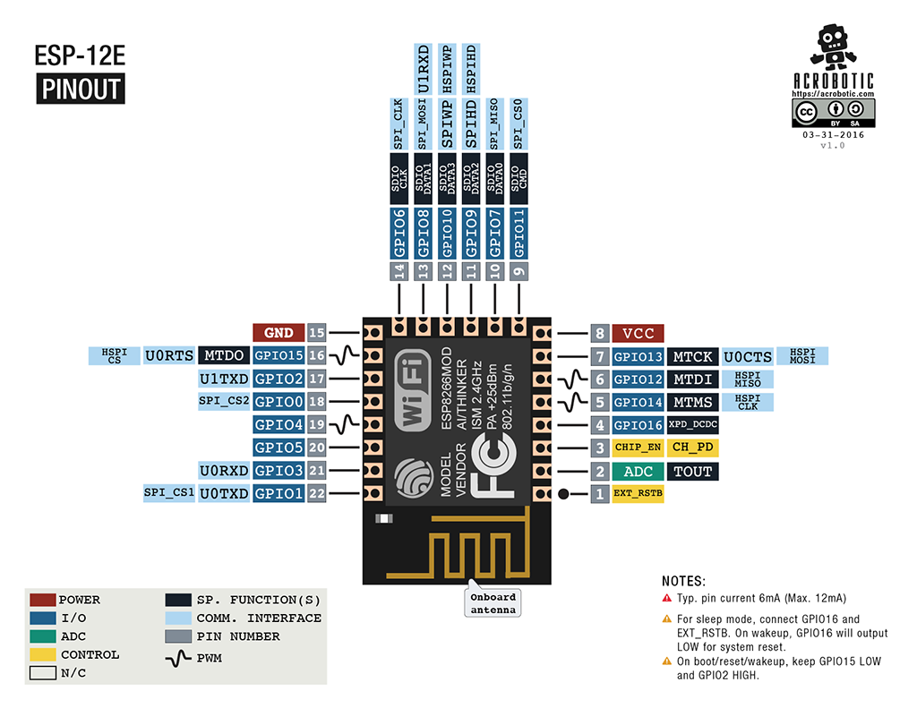
After doing some research, I found that the ESP8266 module is a huge family. There are several types of ESP8266, and the main difference is the replaceability of the antenna. For those ESP8266 modules that came with built-in unchangeable antenna, we can divide them into two types, one is the printed circuit board wiring (such as ESP-01 and ESP-12E), and the other is the ceramic antenna (ESP-11 ).
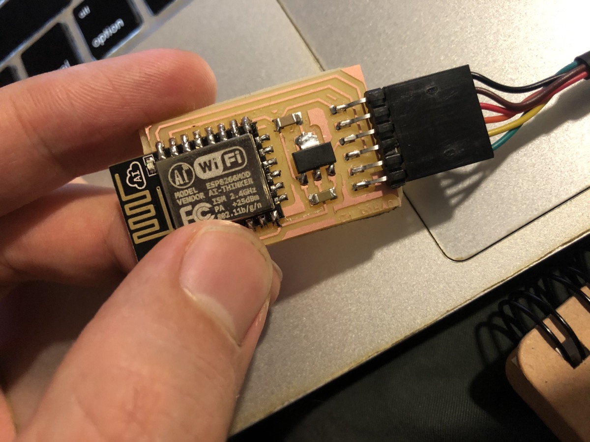
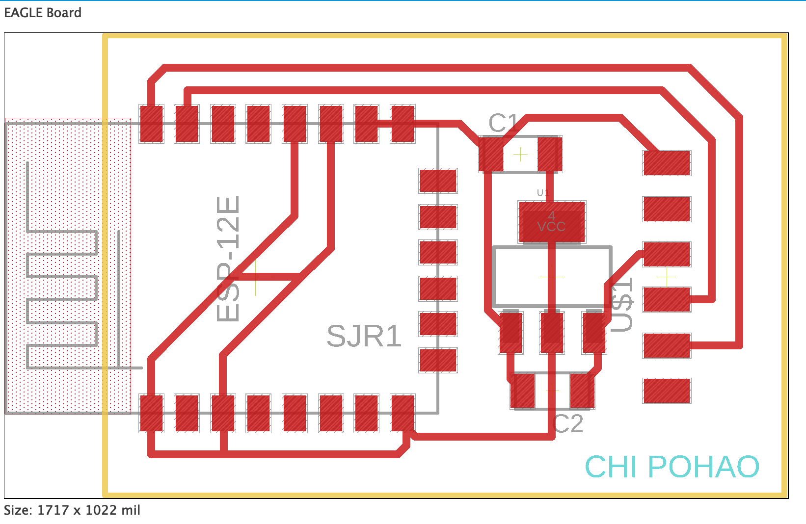
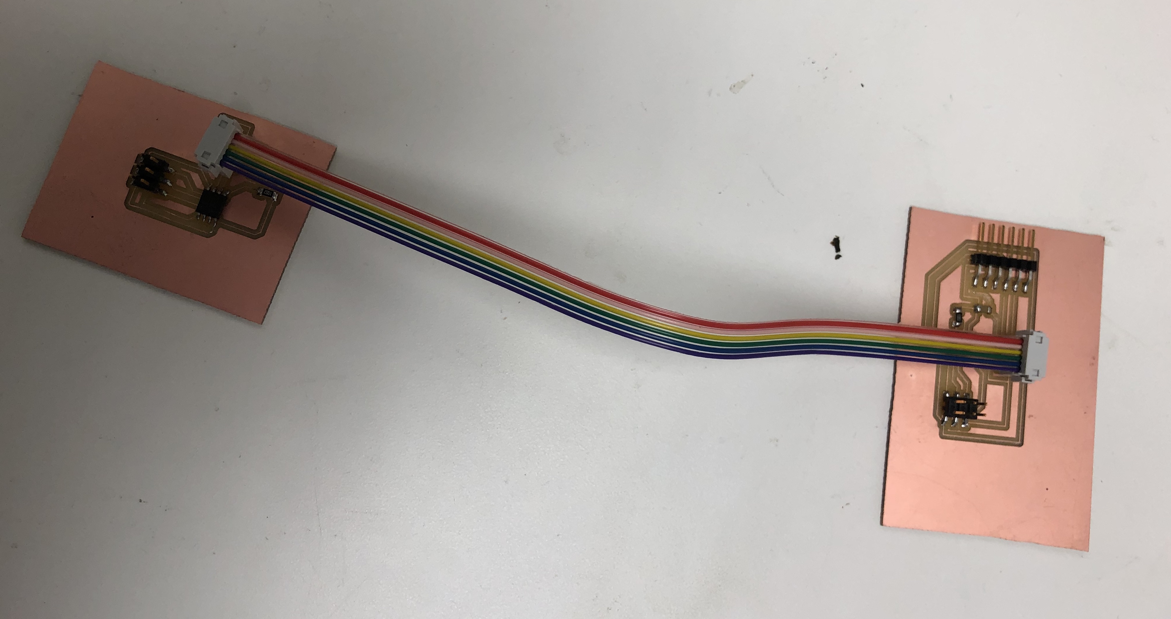
The ESP8266 I found in the CBA shop is ESP-12E. First of all, I need to design and mill the board.

I followed the tutorial from the HTMAA website and ran the test file. To run Neil's python file for ESP8266, you need to indicate the serial port and available wifi connection.
python esp8266test.py /dev/tty.usbserial-FTAV0OC8 115200 "MIT GUEST" ""
Above is what I typed in the Mac's terminal. The order is python command, file name, port, baud rate, and wifi information.
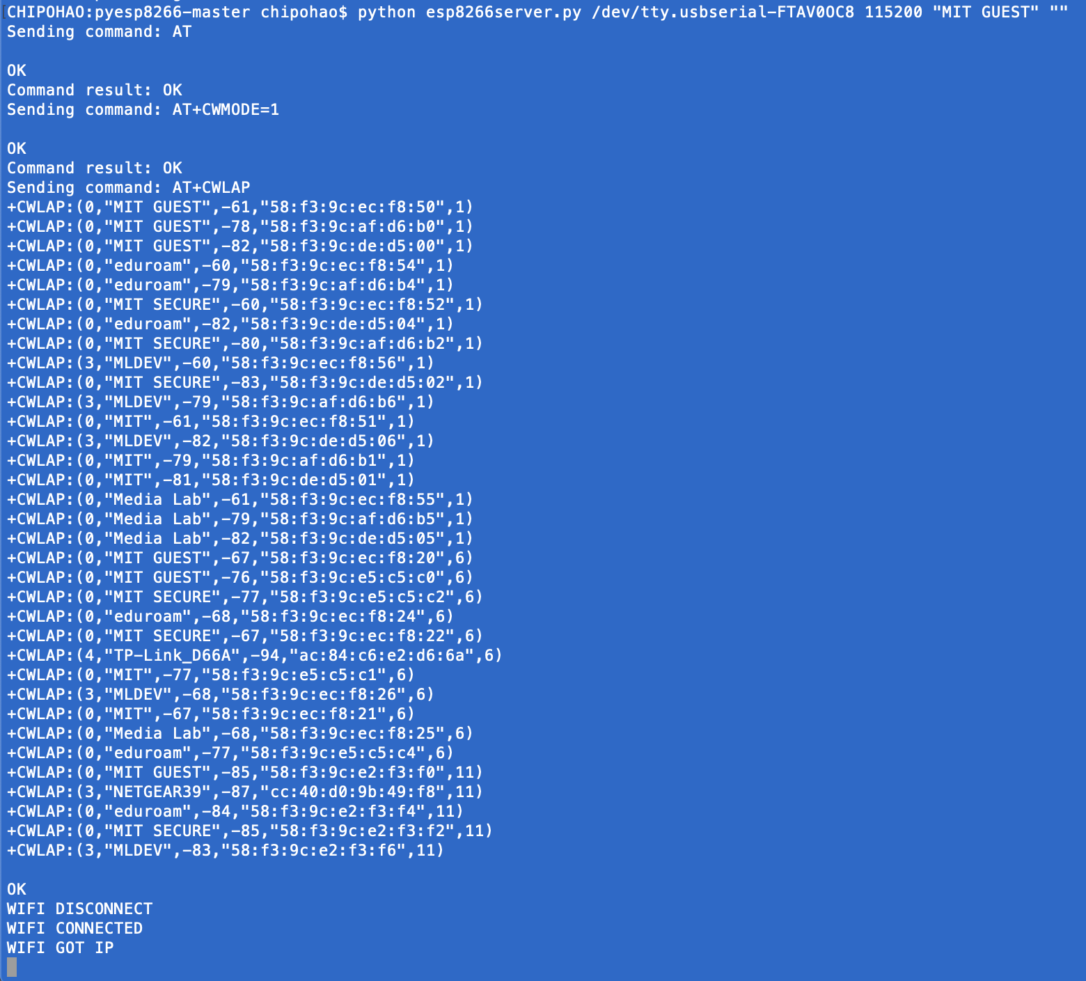
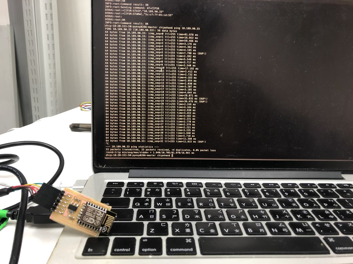
The terminal should return you "Command result: OK" and then an IP address after the "Got IP" message.
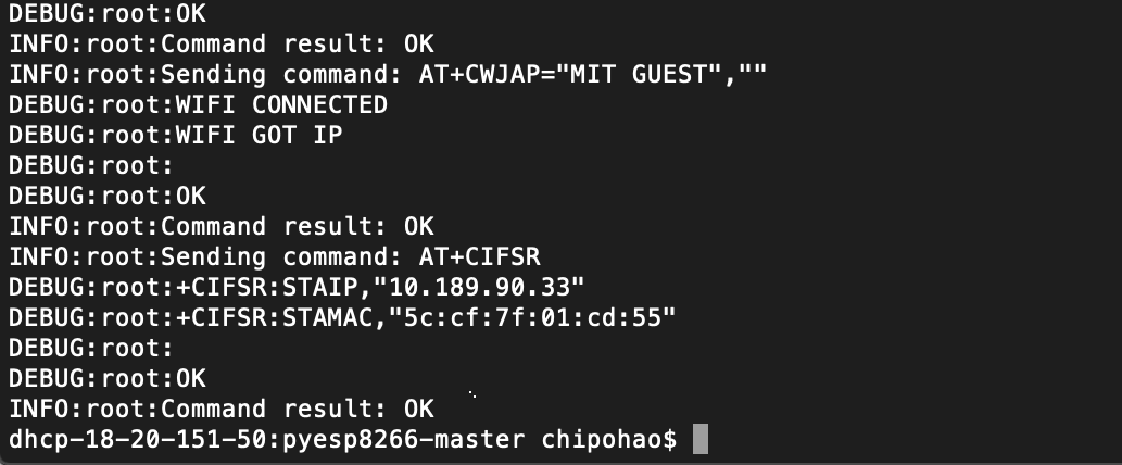
As we got the IP address of ESP8266, we can use the "ping + IP address" command to test the data transmitting. Sometimes it failed and transmitted an empty envelope, but usually, you only need to redo the process or reconnect the FTDI cable to overcome the errors.
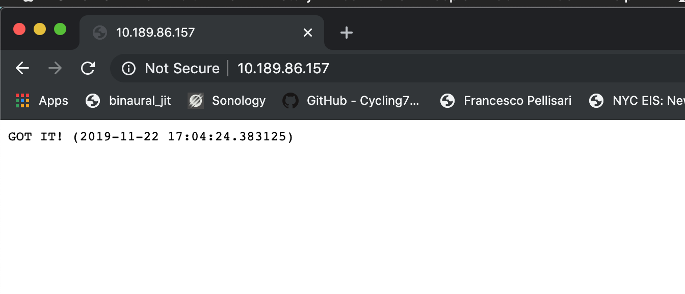
With the test python file, I realized that my PCB is functional and connected to the Internet. Afterward, I ran the "esp8266server.py" to communicate with the webpage..
Serial Communication
For the group assignment, we milled and soldered several new boards and successfully programmed them.
I learned a lot by debugging and try to understand the relationship between current and voltage.

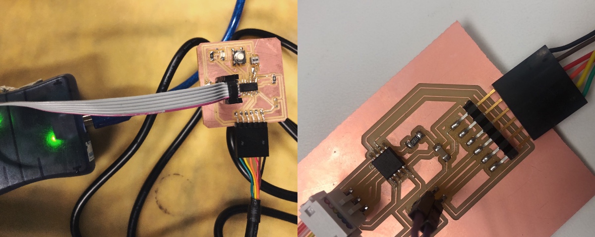
The tiny oscillator helped me to understand the states of the pcb and circuit.

However, it seems that the Python version and installation in my MacBookPro has some conflicts with the program. I couldn't open the pop-up window correctly. I will continue the experiment in networking communication in next couple weeks.

Week12Mechanical Machine Design
Brainstorming
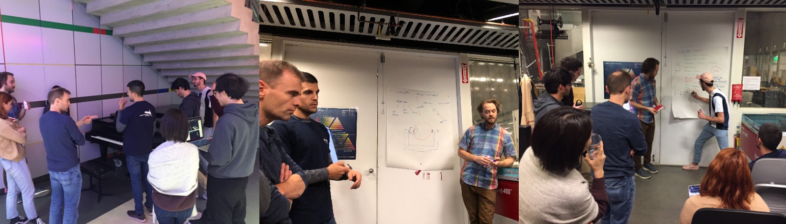
Our first meeting was all about idea brainstorming. We coincided that we wanted to make something fresh and practical in only seven days. We begin with two general directions: food-related machine and sound-related machine.
For the food direction, we talked about making noddles using the additive method and carving apple using the deductive method (we made a trip to the lathe machine and talked about our ideas there). For the sound direction, we discussed making a piano-plating machine (we made a trip to the piano in E15 and realized that there was already a similar project done on a same-size keyboard).
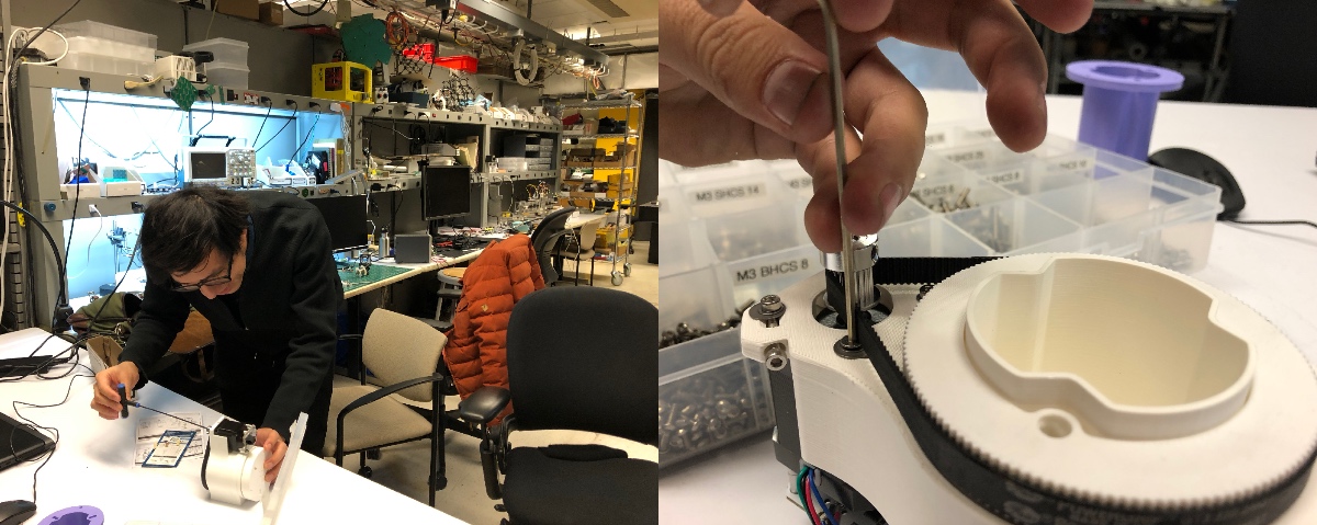
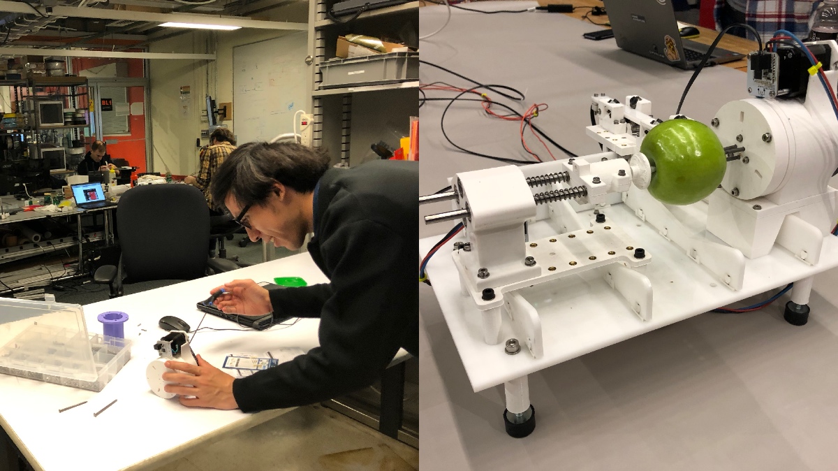
Apple Peeler!
The four-axis restriction constrained first ideas since the beginning, so we went from a printing extruder to a piano-playing machine to agree on an auto-lathe in the end. People in the CBA section are all ambitious and also capable of necessary skills. ACT folks seemed had no specific tasks that could help in mechanical parts.
The brainstorming session was fun but also taking a lot of time. Since we only have less than five days after we finished the brainstorming discussion, we need to separate the duties and work hard as soon as possible to reach our goal. ACT folks seemed had no specific tasks that could help in mechanical parts, so after agreeing on making an automatic apple peeler. We offered to make a documenting video and help with the hardware group. We ended up looking at every part of the process as we had to document everything.
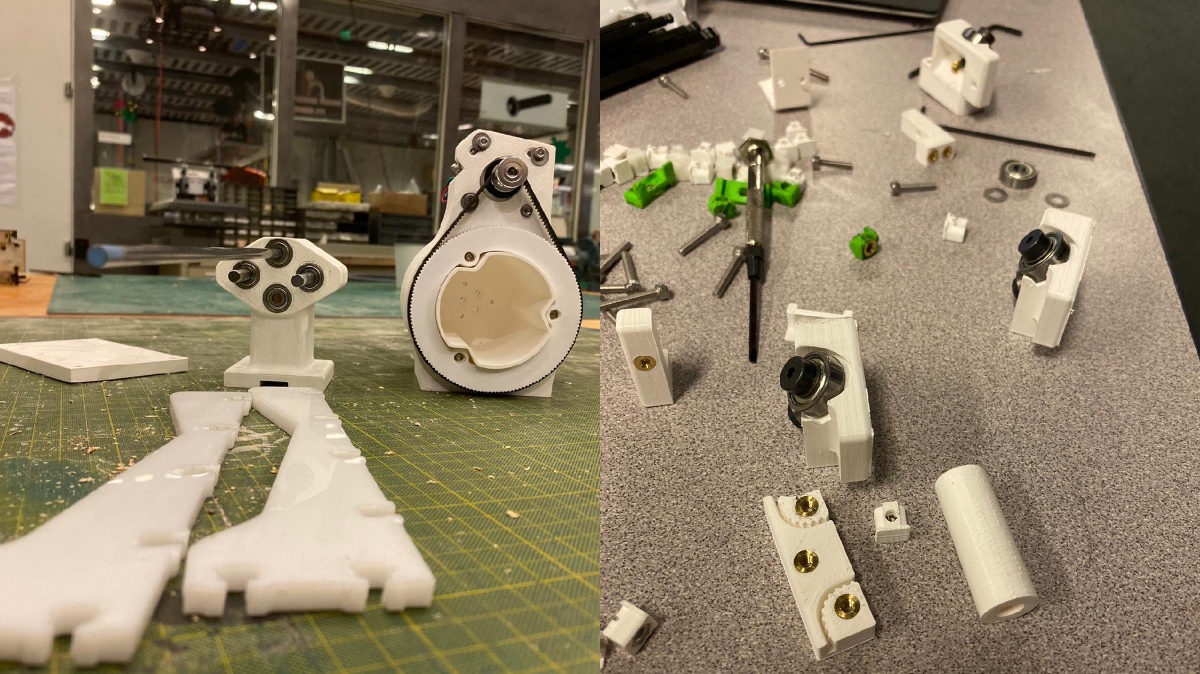
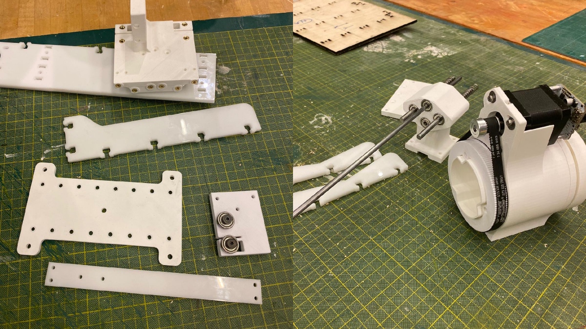
3D Printing and Laser Cutting Parts
On Friday, Alfonso did a prototype based on the machine Jake designed. ACT people offered to 3d print some small parts of this apple peeler. After finalizing the mechanical design, we started to 3D print the parts. I finally got more familiar with Fusion360 software. We got the entire design on fusion and printed out different elements. The first 120 pieces came out quite well.
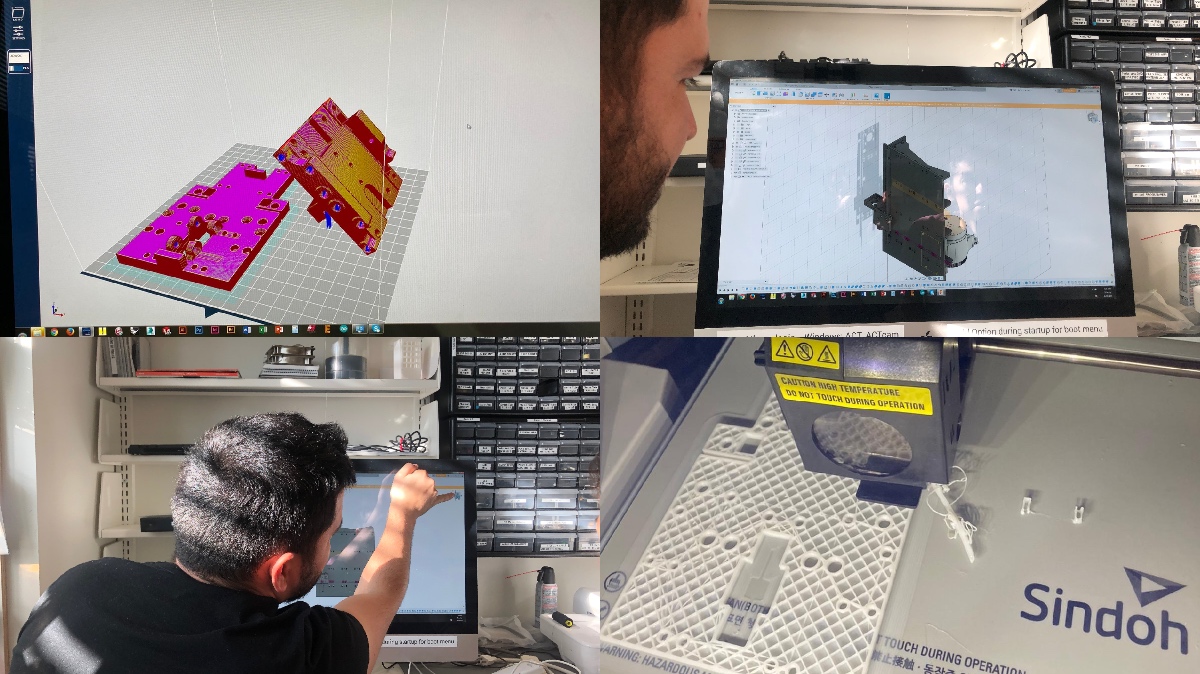
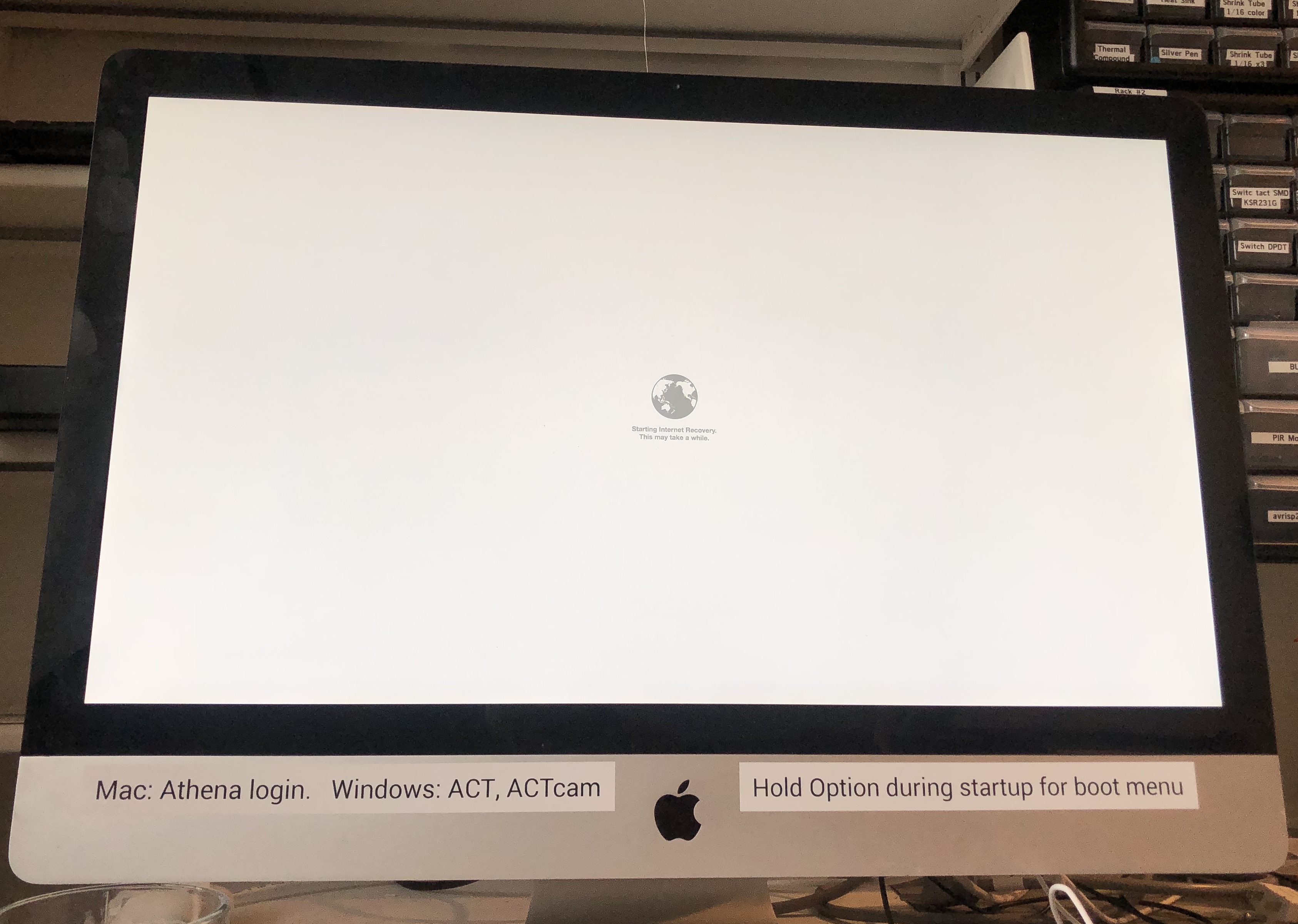
The second try for larger pieces was quite a mess. The computer in ACT electronic studio shut down without any reason and gave us a question mark in a folder icon after restarted. It was quite frustrating as they took about 14 hours to print and failed almost halfway through. The computer kept on breaking also, so we spent the entire day trying to fix this problem. There were lots of failures with Prusa and Sindoh machine. The pieces came out fine eventually, but we had a hard time.

More Meetings
We had several more group meetings along the way, and the electronic team is giving updates and negotiating with the UI team on how to communicate.
Prototyping
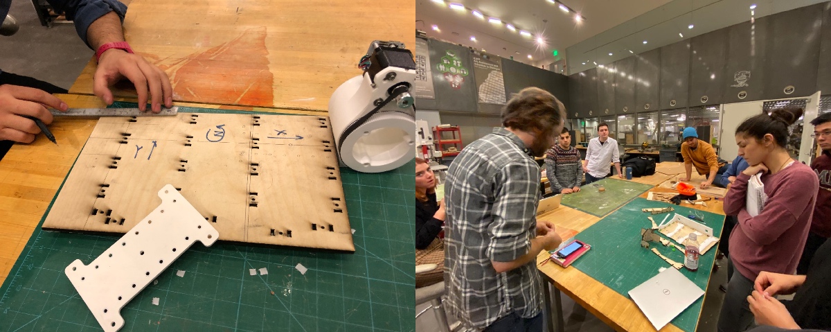
Assembling and Debugging
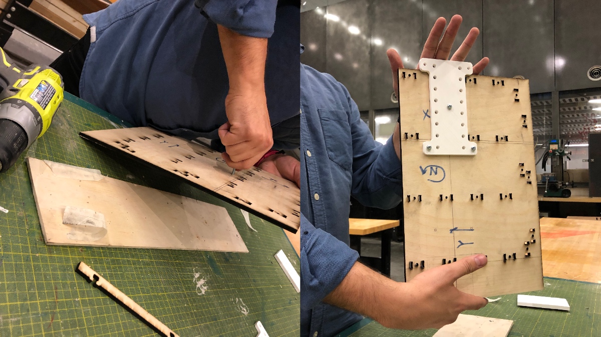
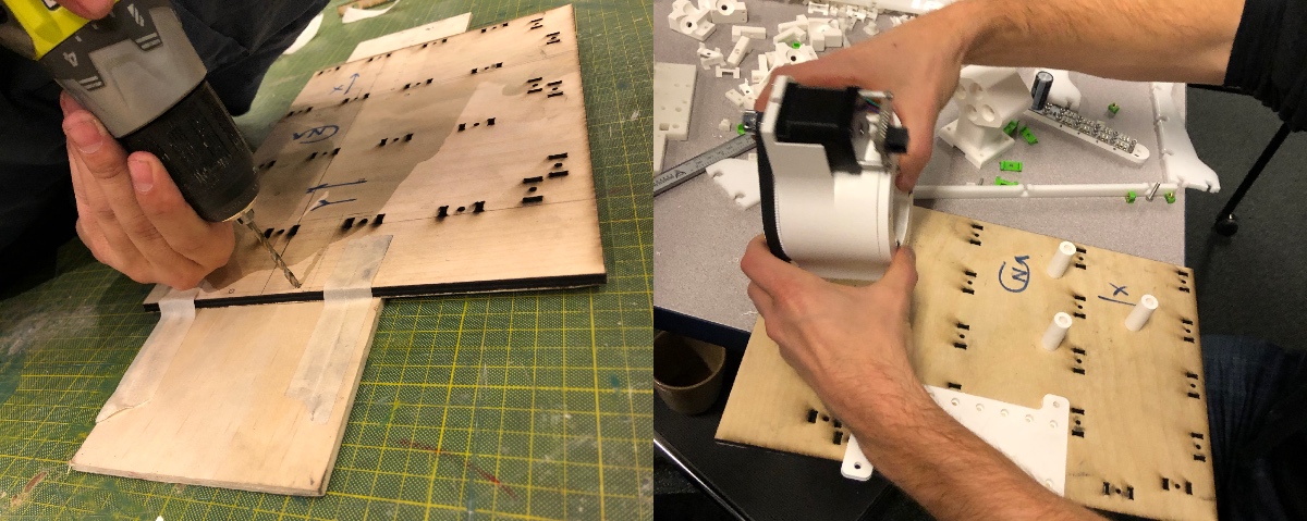
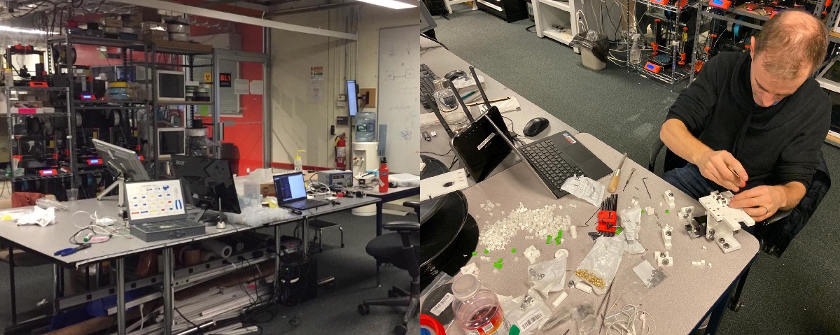
During the weekend, we started to assemble the machine. We did most of the works in the CBA office to ensure that there are always enough tools and knowledge people around. It was my first time entering the CBA office. We began assembling all 3d printed parts — lots of heat pressing and screw and nuts.
I tried to help in the assembling process. There were some small mistakes in the mechanical design, so we replaced some screws and components after confirmed with other CBA people.
Documentation & Video Editing
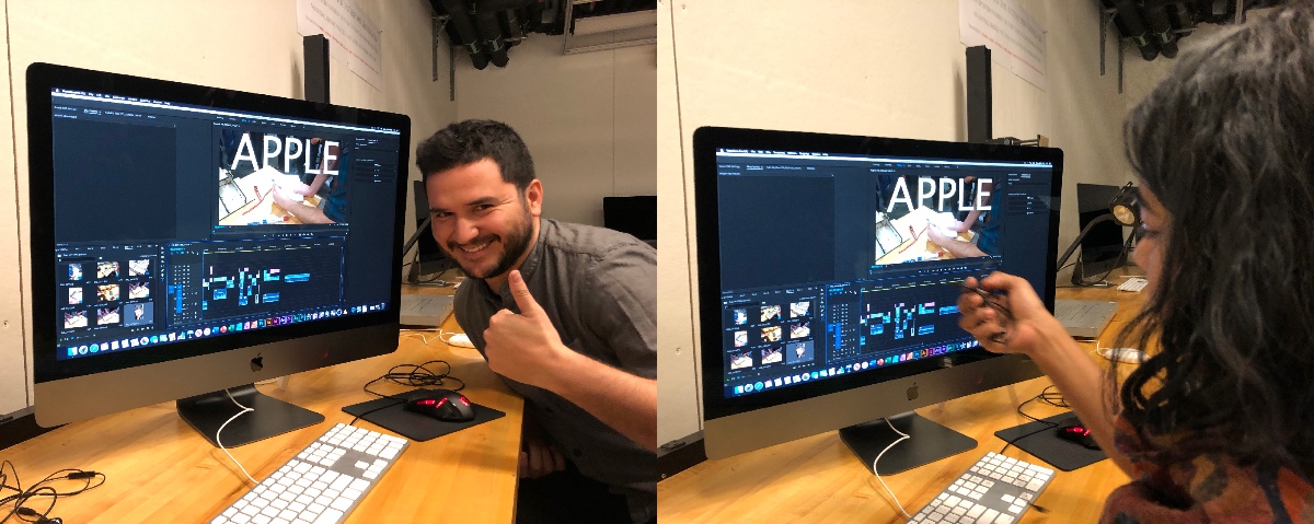
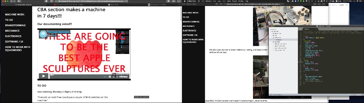
We did most video editing n the IEL, the ACT computer room. We tried different ways to integrated all video clips and images submitted from other CBA people. I opened an MIT Dropbox account for others to upload materials that they considered essential for the process.
We checked out cameras, tripods, and recorders from ACT's checkout room for the final product branding video, referenced to Apple's product promo video on Tuesday, the day before HTMAA's regular class.
This part was exciting as I got the chance to wander around and see how other people were working. Together with the other ACT people, we made a short video documenting the entire process from brainstorming to testing.
You can see the final result of the machenic apple peeler and detials of hardware and software design in the CBA Setction Websitefor machine week.
Week13Interface and Application Programming
This week's assignment is relatively easy to achieve. We need to write an application that interfaces a user with an input or out device that we made in previous weeks, and compare different tool options.
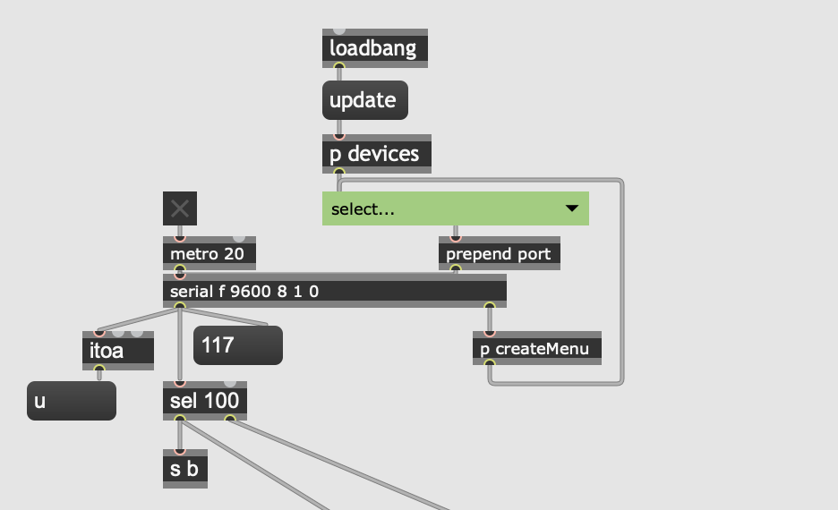
I created an application with "Max" software and "Node.js." Whenever you press the button, the program will automatically choose a breed of dogs and search an image of that kind of dog from the "DOG CEO API" database for you. The Max program was communicated with the Attiny board through the serial port with the baud rate 9600.
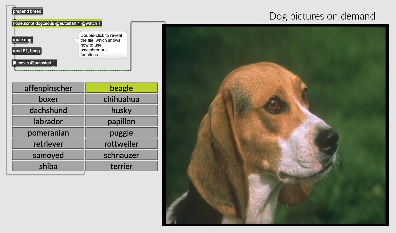
The button board's C code from Neil's Input Device example outputs char "d" when pressed and char "u" when unpressed. The data received in the Max program through the serial port was in binary format. So I use the "itoa" object which can convert integers to UTF-8(Unicode) characters and use the result as a boolean value to trigger the Max program.
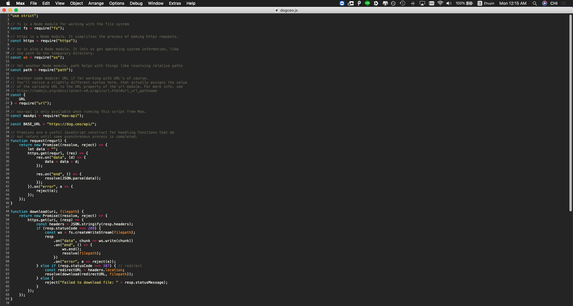
There is an embedded javascript object in Max, which loads the js file to implement the function. You can see in the javascript code. I recalled different APIs to access the DOG CEO API and import it to the Max interface.
Update- Another Experiment
Since I plan to use ultrasonic sensor for my final project, and Emma asked me to hlep for the Interface week's assignment, I made a webcam effect to demonstrate the functionality of the distance parameter.

You can see in the screenshot, I used the distance value from the ultrasonic sensor and scale then to control the "zoom_x" and "zoom_y" parameters of the webcam image. You can see the demonstration below.
Week14Wildcard Week
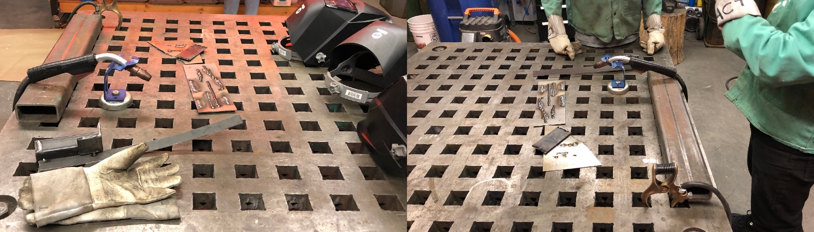
I joined the "SheetMetal" group this week. The training session was in CBA shop, John and Tome gave us a comprehensive introduction of working with sheet metal and related machines.
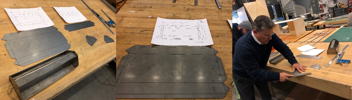
We learned about how to use the metalcutter, and other tools for folding and welding.
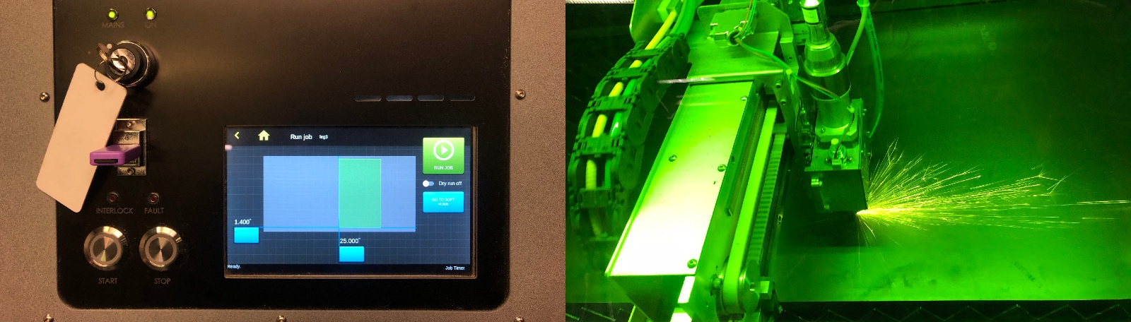
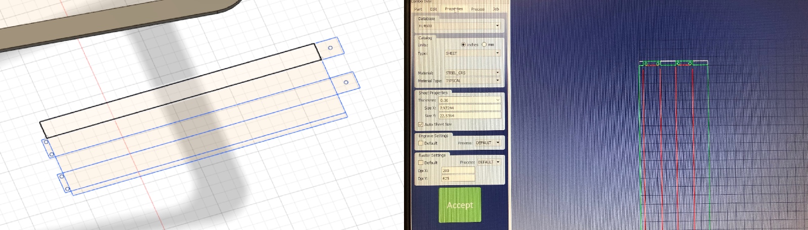
The machine use for cutting sheet metal is similar to the laser cutter. You need to use specific software to import the dxf file with the expected setting. After positioning the models and selecting the material, you can export the fab file to the USB drive and plug it into the machine.
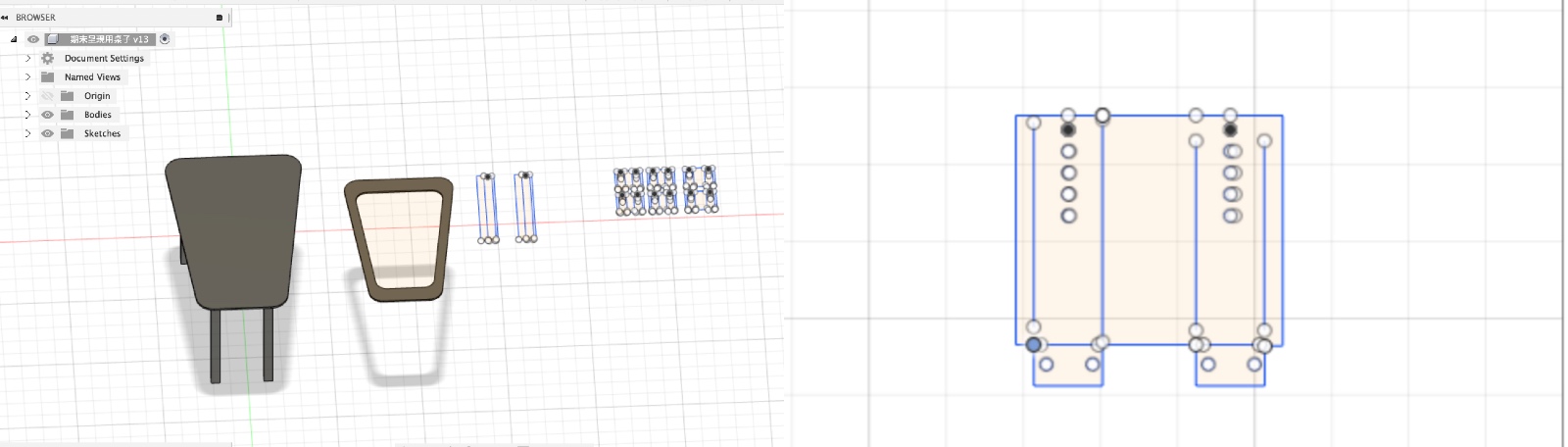
I planned to make an office table with legs made from sheet metal. Thus, I need to design the rules for folding and screwing. Graham taught me welding with large pieces with other dangerous tools.
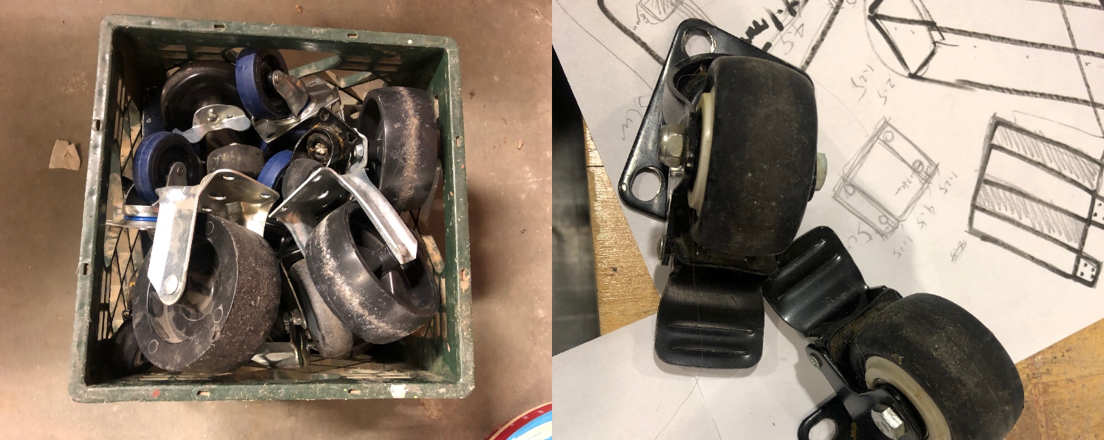
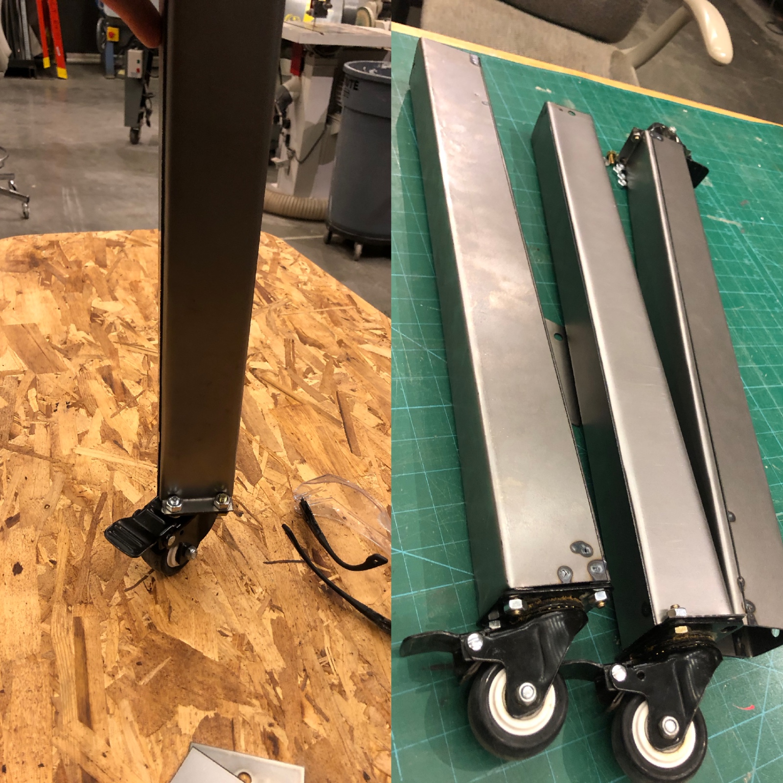
I got some wheels from Mars Lab. I want to screw it to the legs of the table to make it movable.
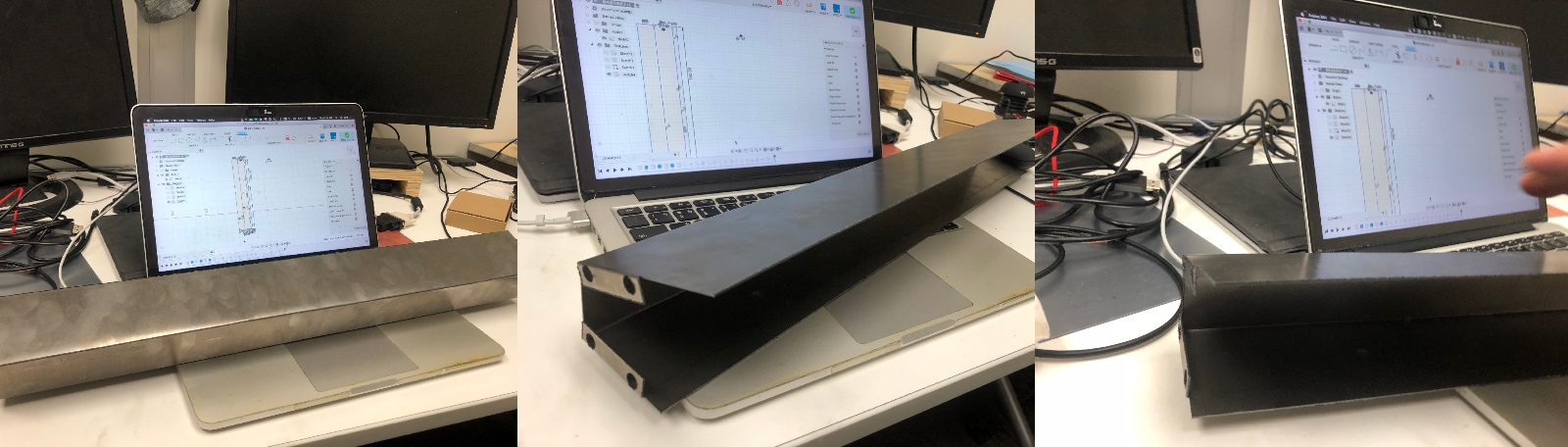
I got some difficulties when using the software to adjust and output the fab file for cutting sheet metal. So whenever I want to change the layout for cutting sheet metal, I need to go back to fusion360 to re-export the dxf files and save them into fab files
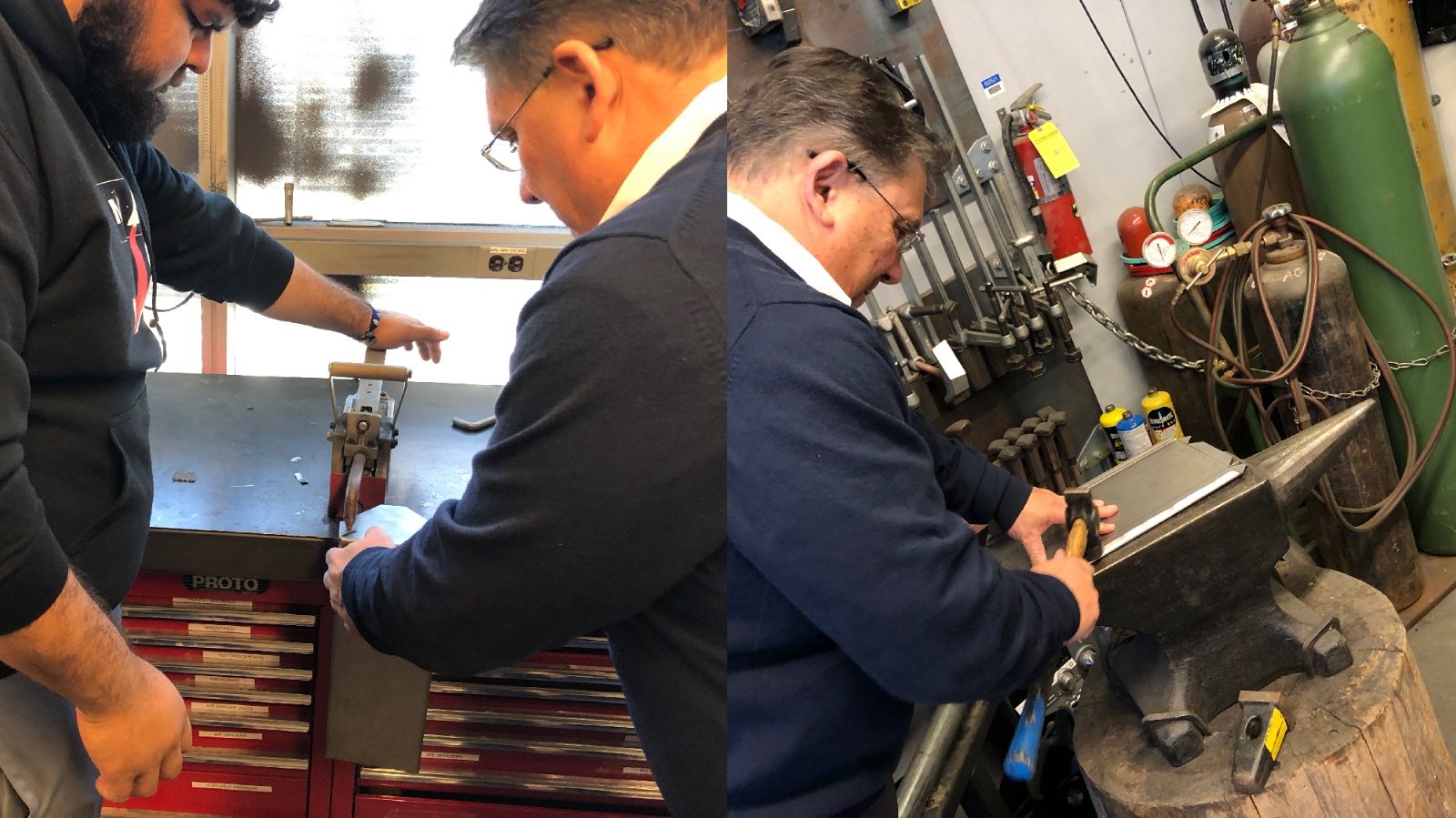
Folding sheetmetal was actually amusing.
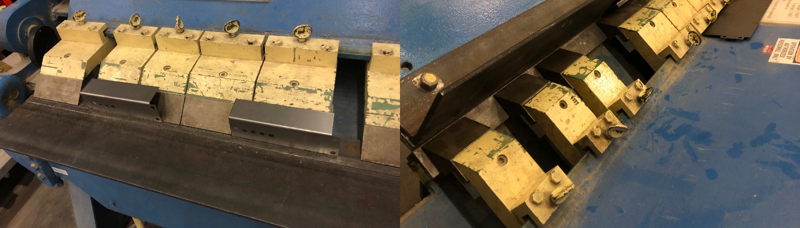
I failed on the first leg I made. The order to fold different surfaces did matter to the outcome. If you start with the wrong, it would be impossible to fold it into a rectangular shape. Also, I found that I should not only cut one piece and fold them into a rectangular leg, instead, but I also need to have two separate pieces to weld them together to form the leg.
And then I got few more legs in various sizes.
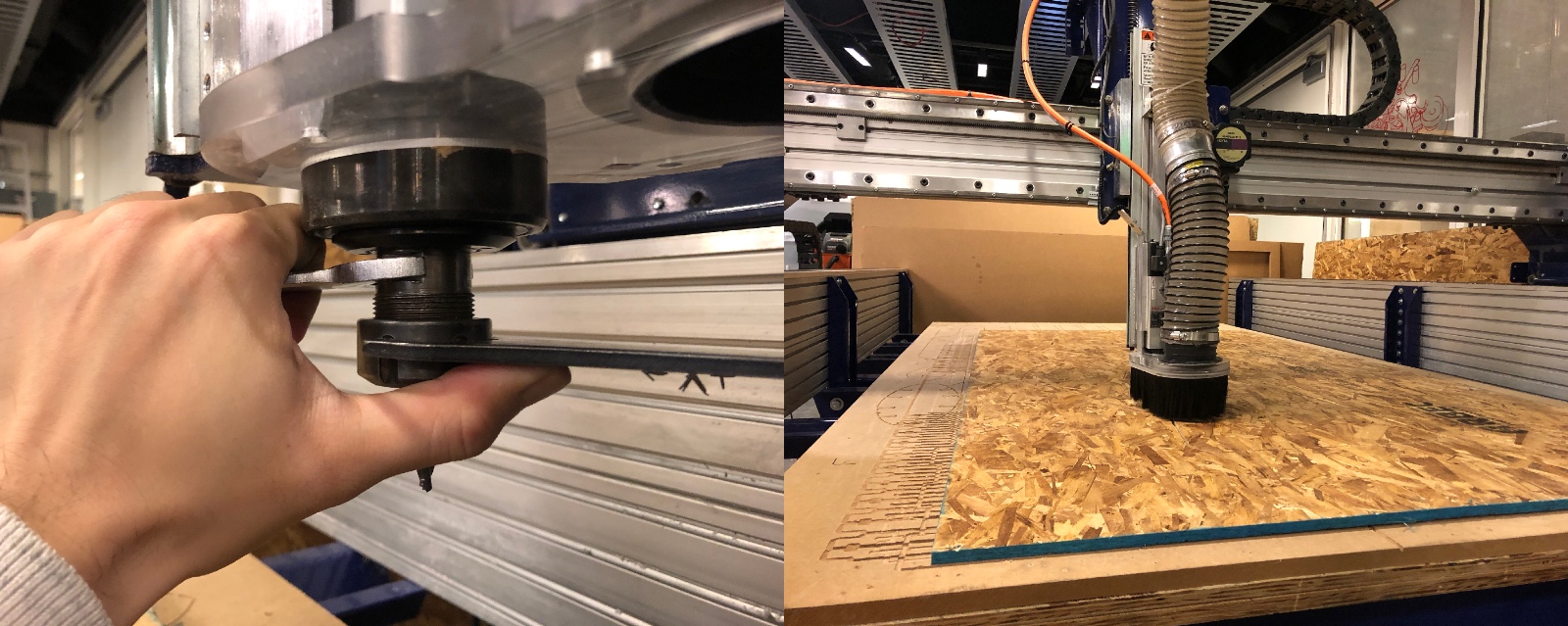
I made the desktop with CNC machine.
I screwed the wheels to the legs. Only one of the legs was fit with the holes on the wheel. It was not that easy to main the quality when folding the sheet manually.
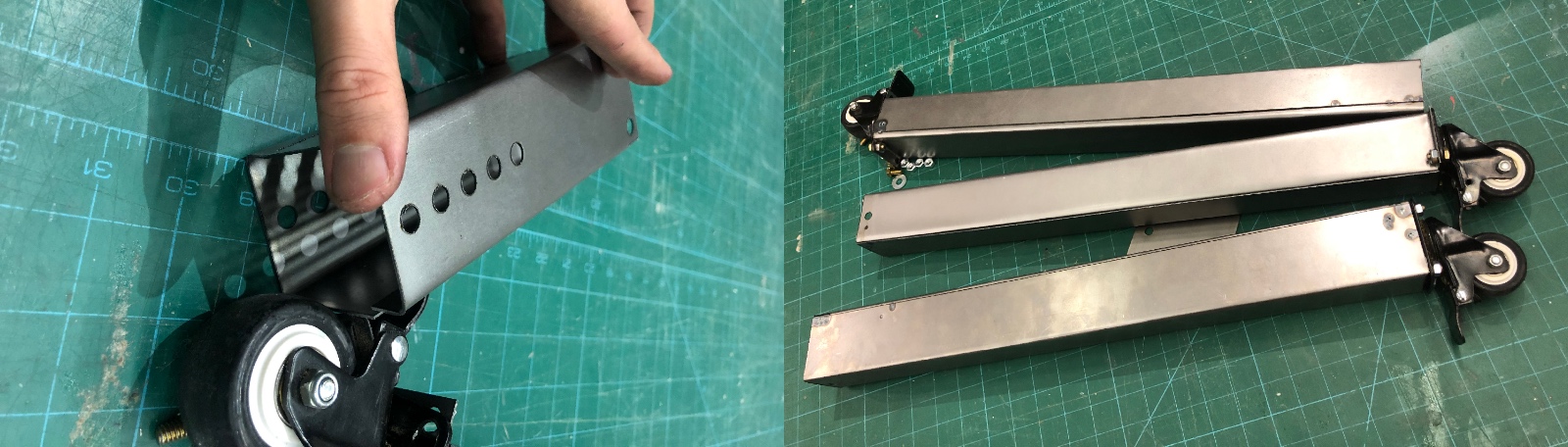
Since the sheet metal we have is not long enough to be the leg for office table, I designed the other part with screwing hoes as the joint to attach to the bottom of desktop.
I pounded on the sides of the joint parts to make it stronger.
I haven't finished it since some joints were in the wrong sizes. I don't know how to make it fit into the socket of the table leg, so I tried to cut the joints with different scalings, from 98% to 95% of the original size.
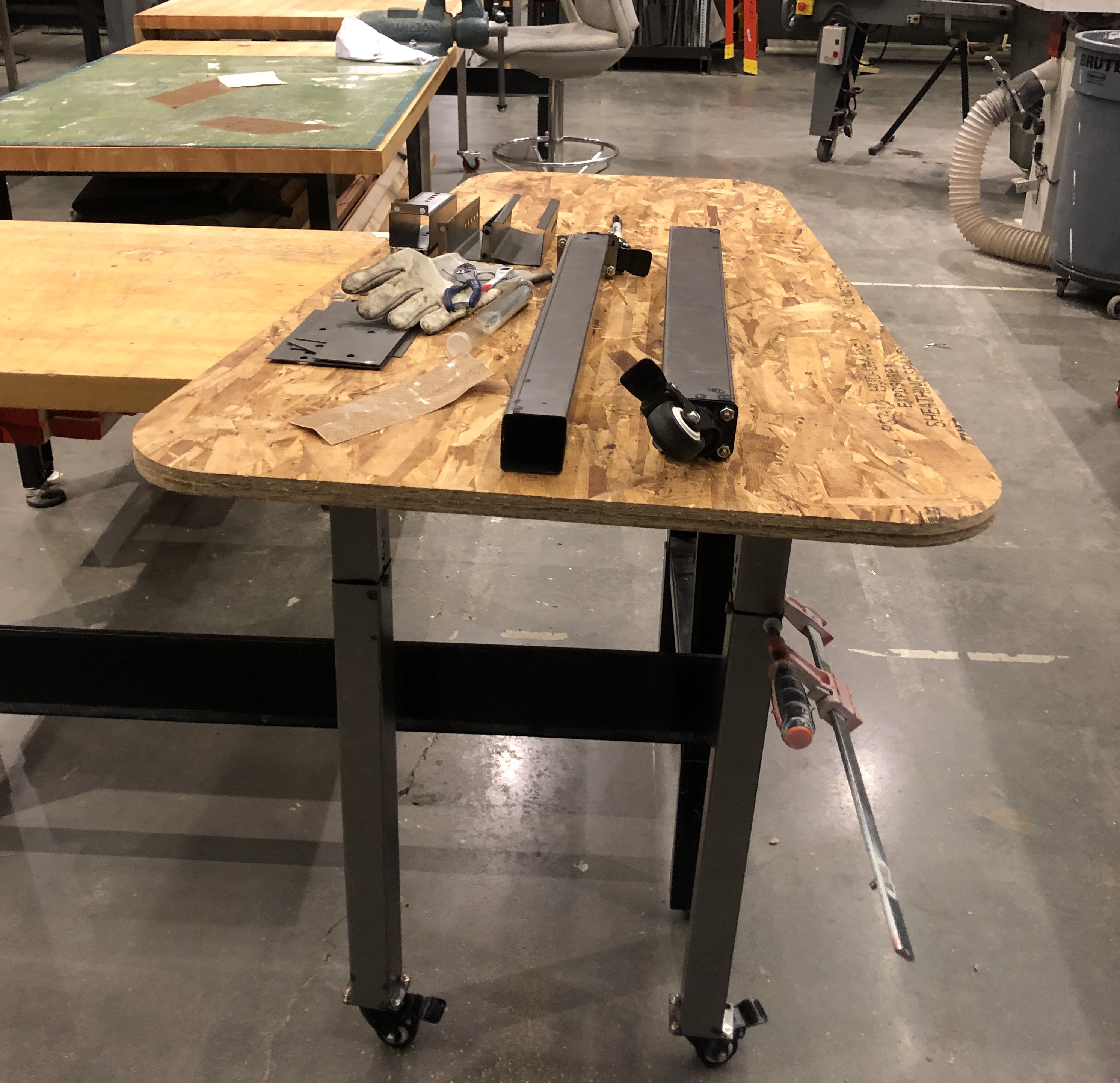
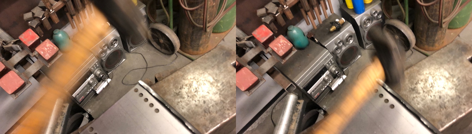
You can see my temporarily result above. It is a little bit unstable, but I learned a lot during the process. Below is the operation of the metal cutting machine.