Week1 Introduction
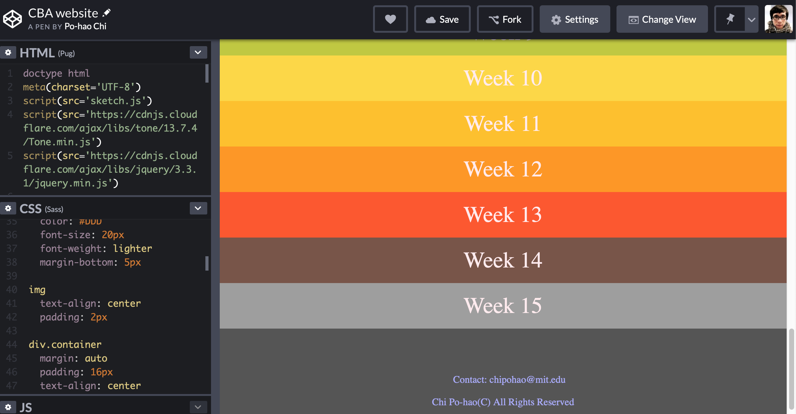
In the first class, Neil gave us a comprehensive introduction about the principles and applications of Fab Academy, as well as basic concepts and tools of computer-aided design. We learned about the version control tool -Git, a project management tool for improving the efficiency of project maintenance. We were asked to create a specific website to document the process for each week. Since I prefer to code HTML with Pug and CSS with Sass, I decided to start constructing my website layout on CODEPEN, a platform that allows the user to see the effects of every adjustment in real-time. It can help me to get used to the web-logic in a practical way.
I usually use Max (published by Cycling74 company)- a GUI programming language designed for artists and musicians, in combination with other creative technologies in personal artistic practices. Therefore, most of my works are software-based without physical elements. I want to challenge myself to design and make physical objects that people can interact with as the final project of this course.
Final project idea
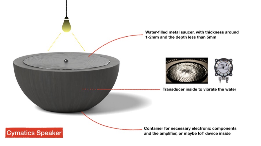
The initial concept is to create a cymatic installation that works as an IoT device. I don't have experience in any kind of visual or production design, but I wish I could build up a device that incorporates physical parts, electronic circuit, input/output and customized program to implement the interaction with computer-aids design process. I had made a demonstration with large size stainless steel metal parts with a high-power transducer to create cymatic effects. You can see a documentary video below.

Week2 Computer-Controlled Cutting
During the second-week class, we went over various tools for 2D and 3D design. The focus was on two computer-controlled cutting techniques: the vinyl-cutter and the laser cutting machine.
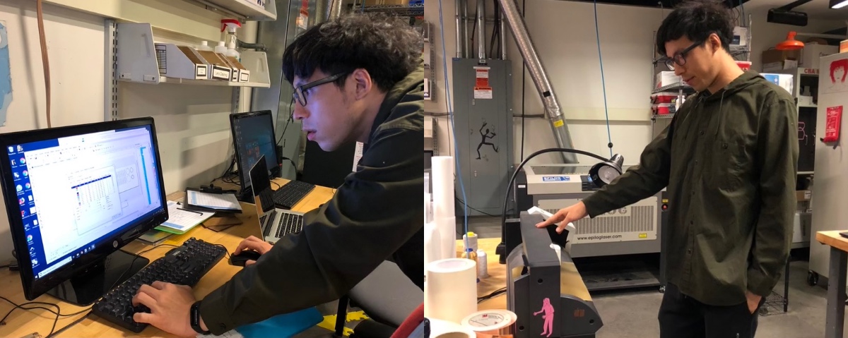
For the group assignment, we characterized the laser cutter setup and tested different parameter settings. For the individual tasks, we had to design a parametric press-fit construction kit and make something with the vinyl cutter. I did several unsuccessful experiments with devices in the CBA shop. However, I got some initial senses of the differences between laser cutting and raster engraving.
Vinyl Cutter
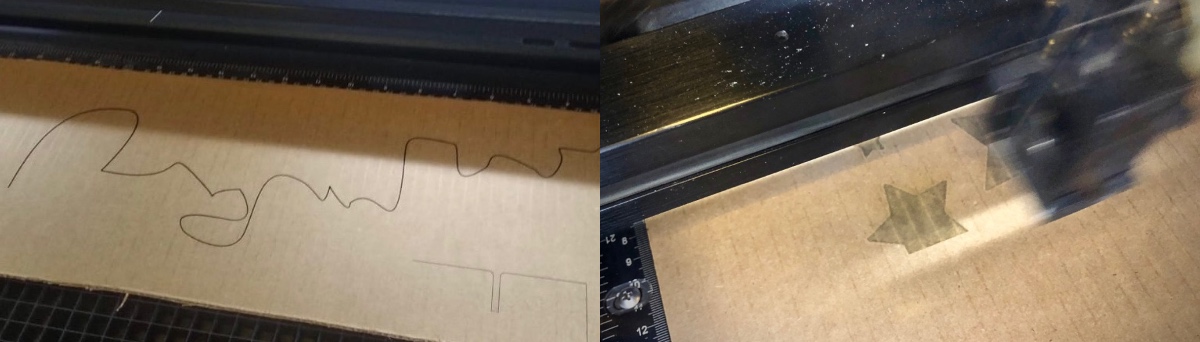
For this part of the assignment, I did numerous experiments and tried from failures. In the beginning, I decided to cut my name but forgot to adjust the force parameter of the machine so I can barely remove the vinyl from the plastic paper.
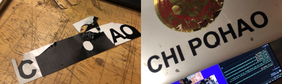
Afterward, I increased the force and got delicate cuttings.
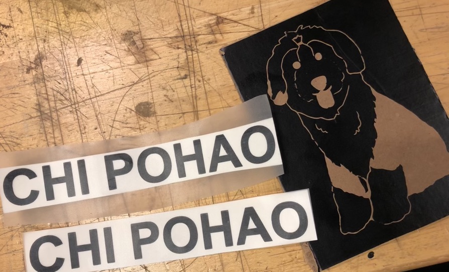
After I was a little familiar with the operation of the vinyl cutter, I modified the design of my dog in Illustrator, and send the file into both vinyl cutter and laser-cutting machine. You can see the result in pictures below.

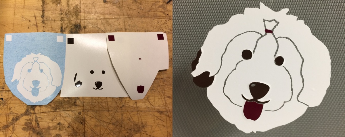
Finally, I applied more than one color of the vinyl to form a pattern and stick it on my studio door. I also cut many of my dog.
Laser Cutting Machine
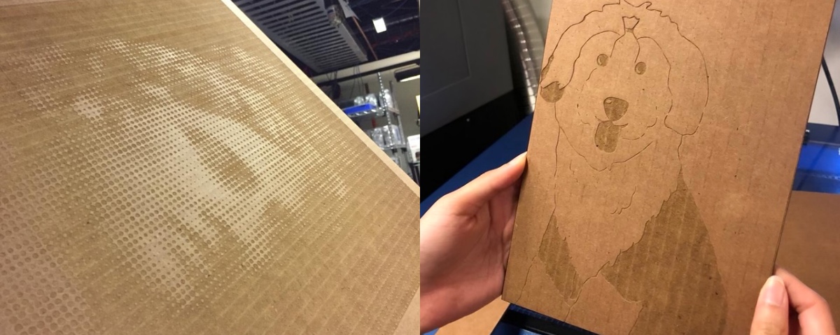
To characterize our laser cutting machine with power, speed, PPI, kerf, focus...etc., my ACT classmates and I tried different sets of parameters on the device for either cutting and rastering.
If we want to make the laser cut through the cardboard, the power parameter could be 100 with speed not higher than 2.5 and PPI set to 200. For rastering, we adjusted the speed from 30-50, with the power range from 50-80. The different combinations caused various effects, which depend on personal preference.


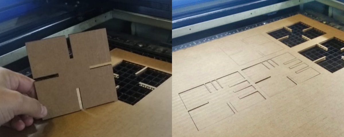
I tried to make a stool with latches and connectors that our teacher mentioned in the class. During the design process in the software, I had referred to some basic online tutorials for constructing a simple form with duplicated support elements and the upper, middle, lower layer's connection holes.
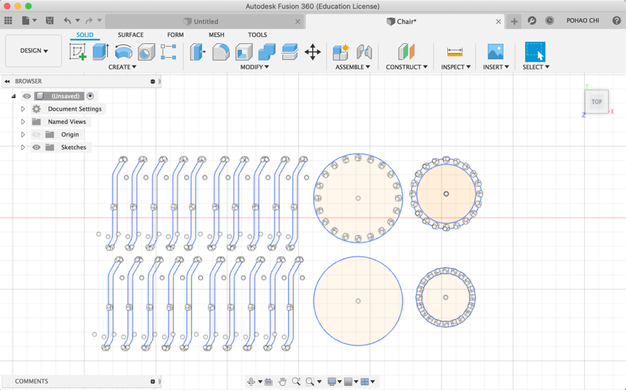
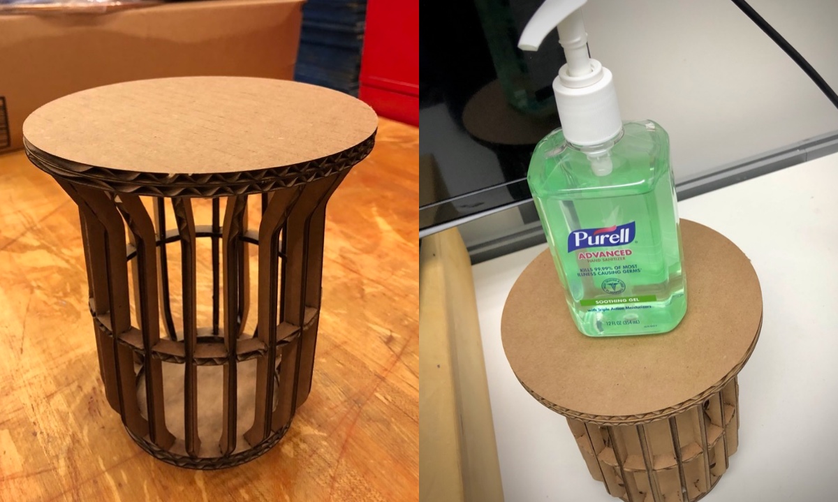
It was not an easy task for me to assemble all the separate parts. I found that cardboard is too soft for the connection of components, and I should have better performance if I use materials like wood or acrylic.

Since our cardboard is around 4mm thick, what I made is a small version of stool. However, it can still be a small platform for me to place objects. I also made several stationery boxes, you can see the assembling process below.
I am happy with the outcome, and I will keep learning more about the uses of Fusion 360 in the next couple weeks.
Week3Electronics Production
This week we learned how to use Roladn SRM-20 milling machine to cut out a PCB. The assignment was to solder the PCB and program it to make a programmer. More precisely, a FabISP in-circuit programmer. We use SRM-20 for this week's practice.

The first step was to mill the PCB on the Roland milling machine. We use Mods for loading the PNG file and adjusting the parameters of milling.

The Mods interface need to be opened with terminal commands. It communicated with the machine via websocket protocol which is convenient and pretty easy to use.

At the beginning we encountered some failure due to the Max Depth parameter was not high enough. It took more time with a higher Max Depth setting but you can get a better milled PCB. I milled two PCB just in case.
We also practiced soldering with little tiny components. I really enjoyed the soldering process. I have some experience in soldering audio cables and contact mics but not really done that for years.
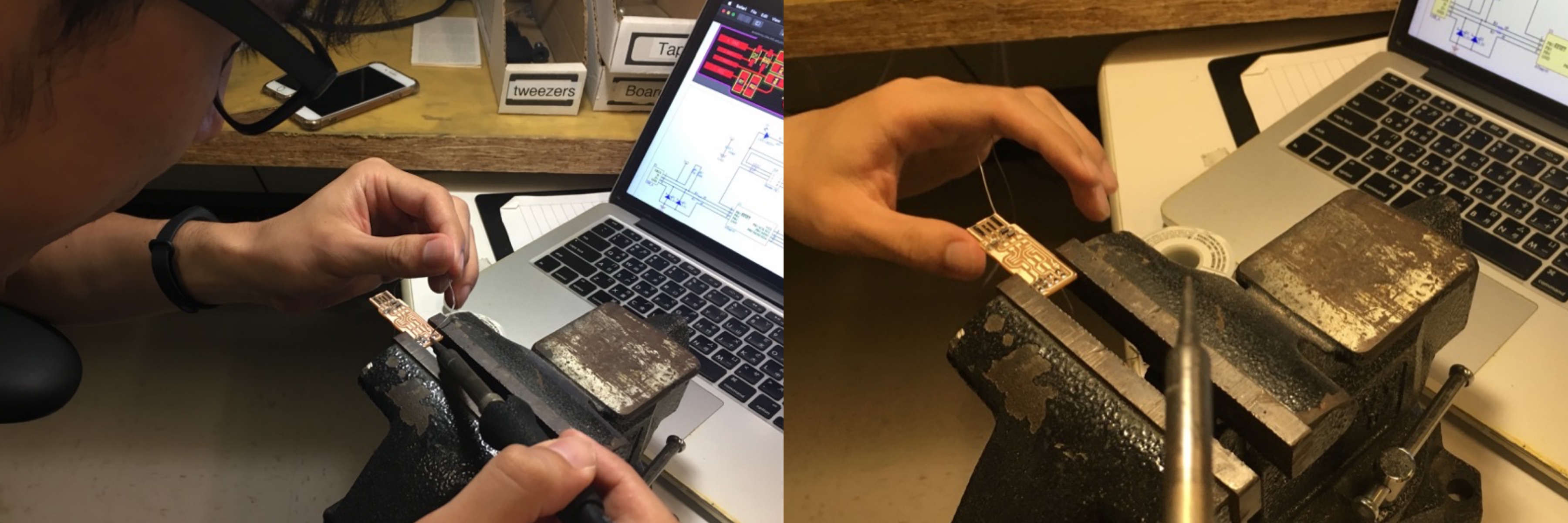
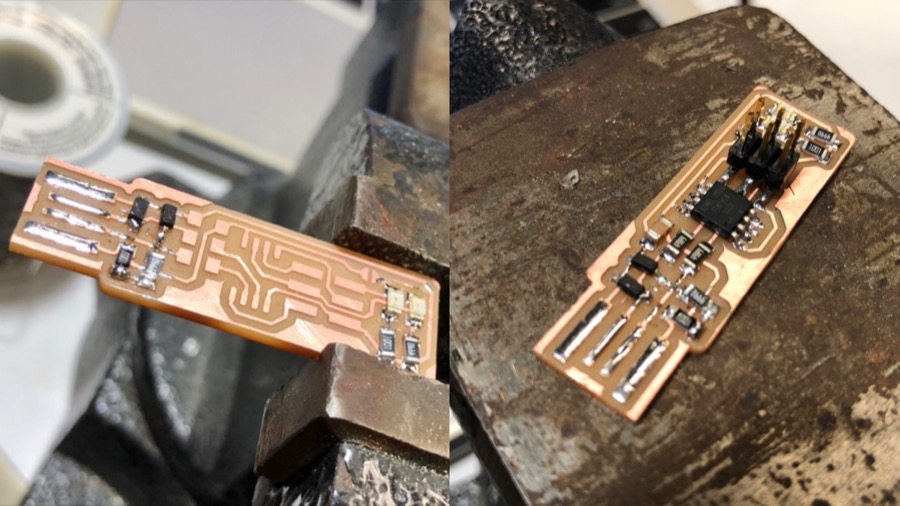
After figuring out how to put the directional leds and diodes in a correct way, I made two soldered PCBs and both of them lit up Red LED when plugged to 5V power.

However, one of them has never working, but the other one is fine. I followed the instruction on Brian's page and finished the operation in the terminal.

I use Graham's programmer to program it. Now it became a fully functional USB programmer, and can be recognized by the computer, which is amazing!

Week43D Scanning & Printing

This week we worked on 3D printing and scanning. The assignments were to design and print out a 3D object that can't be made subtractively and to experiment 3D scanning. I spent quite a lot time to experiment scanning and printing with different machines and material. Most of them failed but I documented the process as references to future students of this course.
3D Scanning
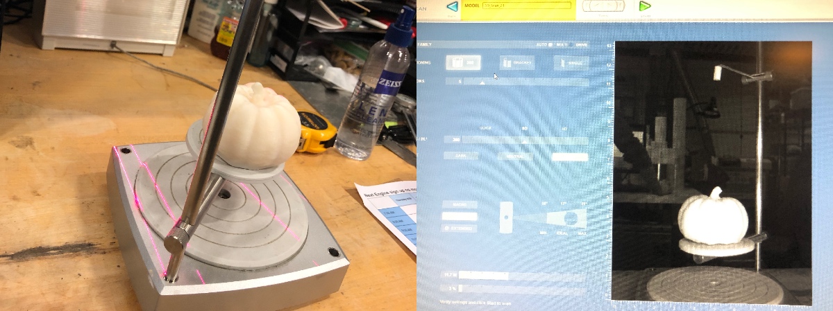
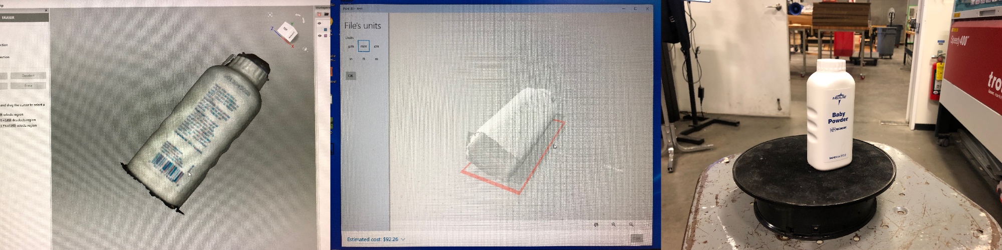
I did several unsuccessful tests on both Artec Studio 13 and Next Engine scanner. It was really difficult to get a complete model and easily be affected by external disturbances.

Even an ordinary bottle looked strange after filling the hole.
The fluffy penguin couldn't be scanned either, since the fur interfered with optical reflections.
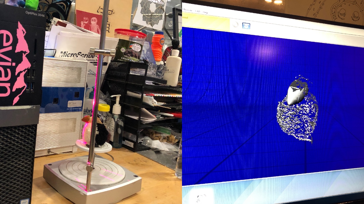
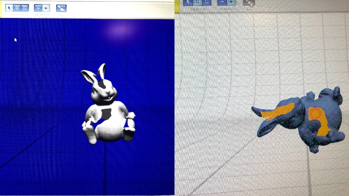
I then tried to scan a small rabbit night light with smooth surface. It looked nice in the software when finished the scanning and fusing process. Only few holes left and need to be filled. However, the computer for the Next Engine 3D scanning was too slow to work on visual processing, and the software crushed before completing the task.
3D Printing
I tried to make something foldable to form an outer covering without support material. I divided it into 3 different STL files to fit the size of 3D printers.
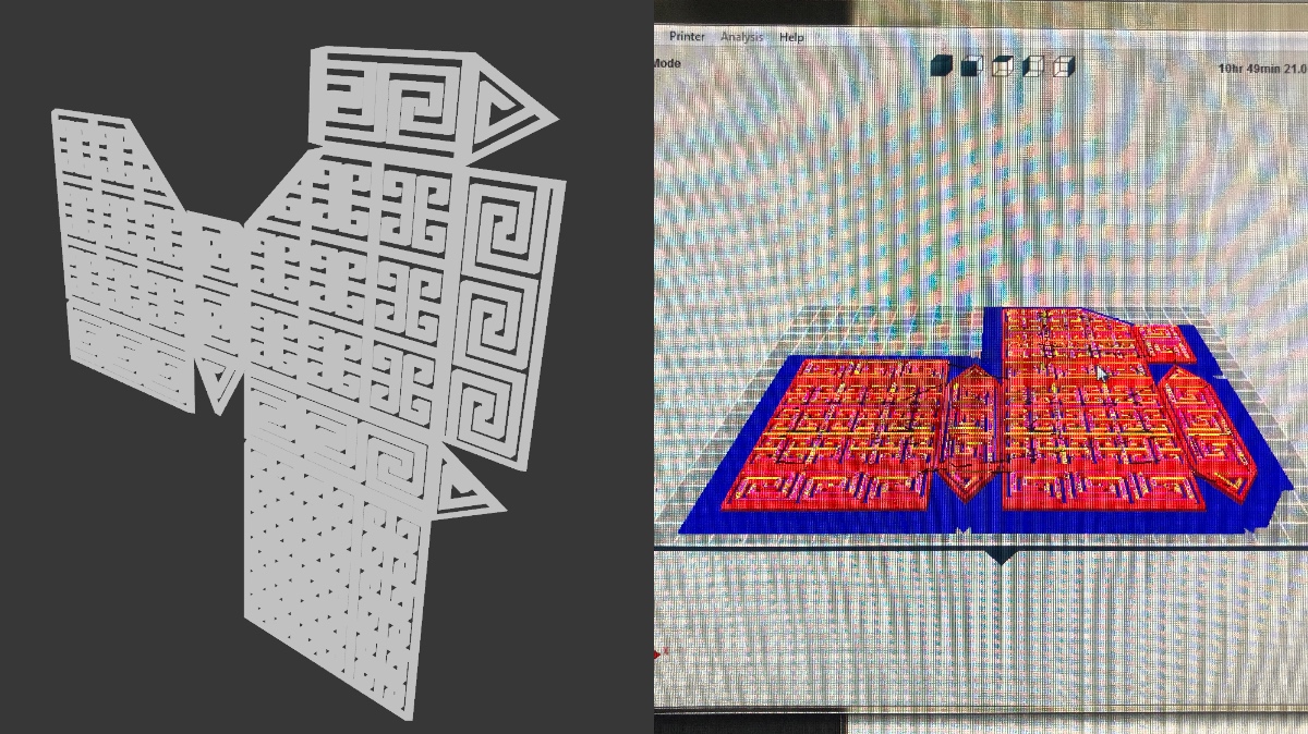
I printed it out with standard PLA but also with the Connex printer. However, my design was failed with Form3 since the structural was too skinny that may be torn off after the bathing process.
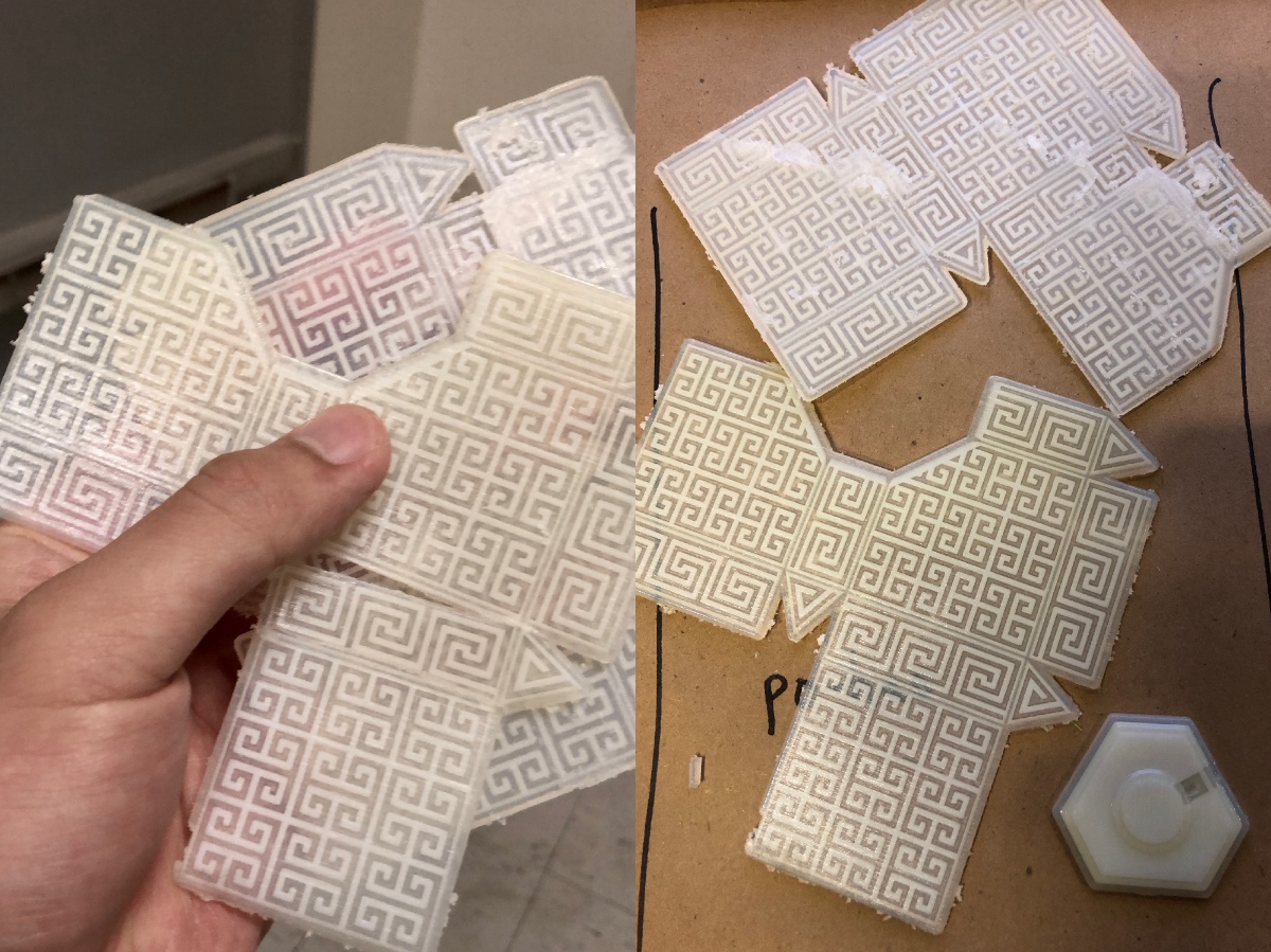
Due to the thickness error of the layers, the printed object could not fit adjacent sides. The joints were too fragile, which caused damages during the assembly process. The result was not as good as I expected, but I have no time to re-print it this week. You can see the final outcome below.
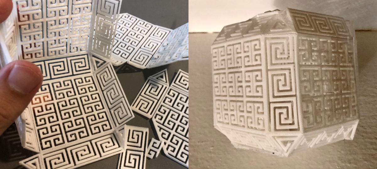
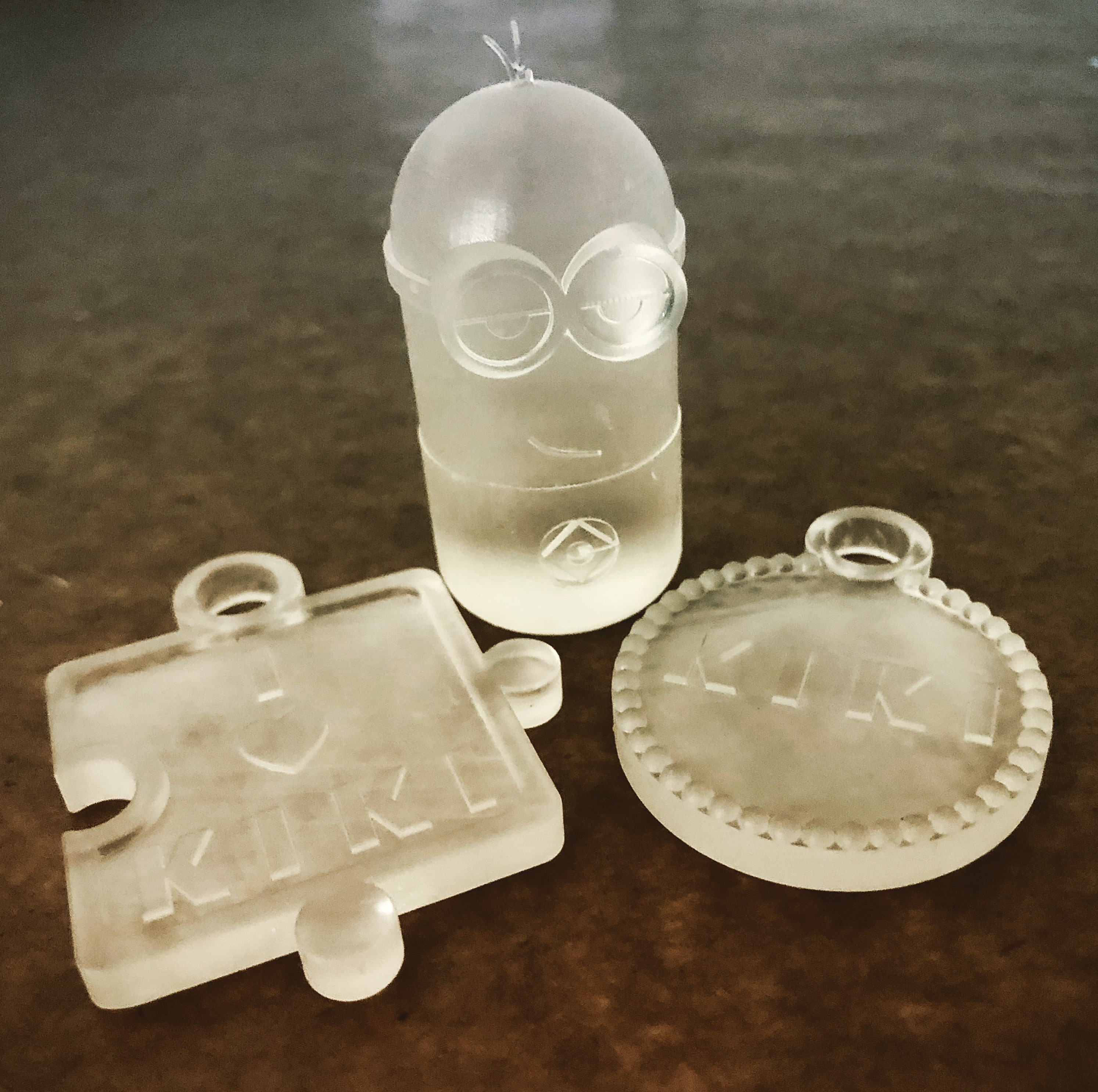
I made several different models and printed them with Form3. They all looks amazing. I learned that how design is important to different tools.
Week5Electronics Design
This week is similar to week2. We need to use equipment in the shop to observe the operation of a micro-controller circuit board as a group and to design, mill, and program an echo hello-world board individually.
Board Design
I used Eagle to redraw the board. My classmates and I downloaded the fab lab library for necessary components and imported the "eagle_fab.lbr" file into the Eagle Library Manager. After pressed the "Use" button, we were able to expand the library folder to browse different libraries in the "In Use" tab.
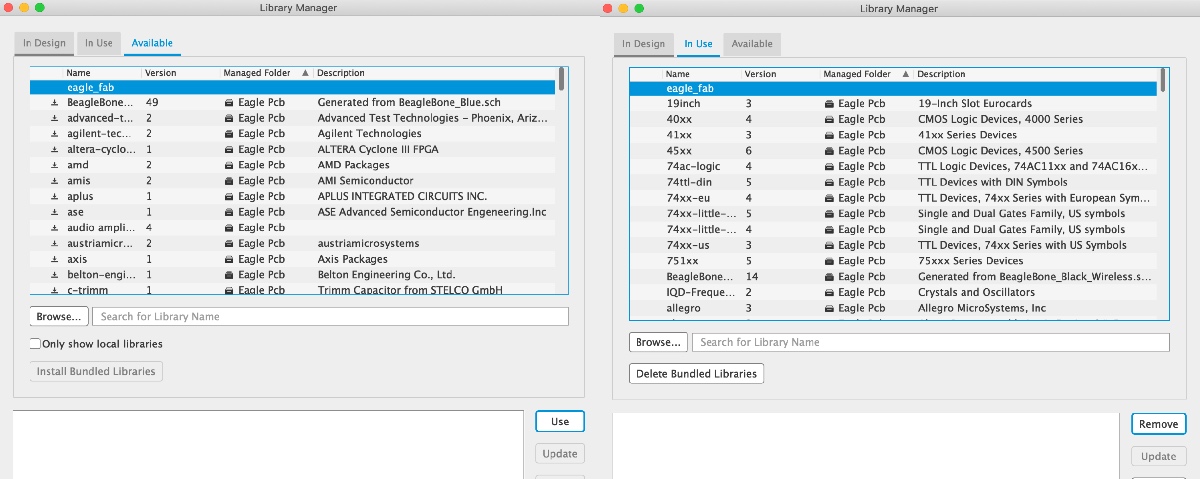
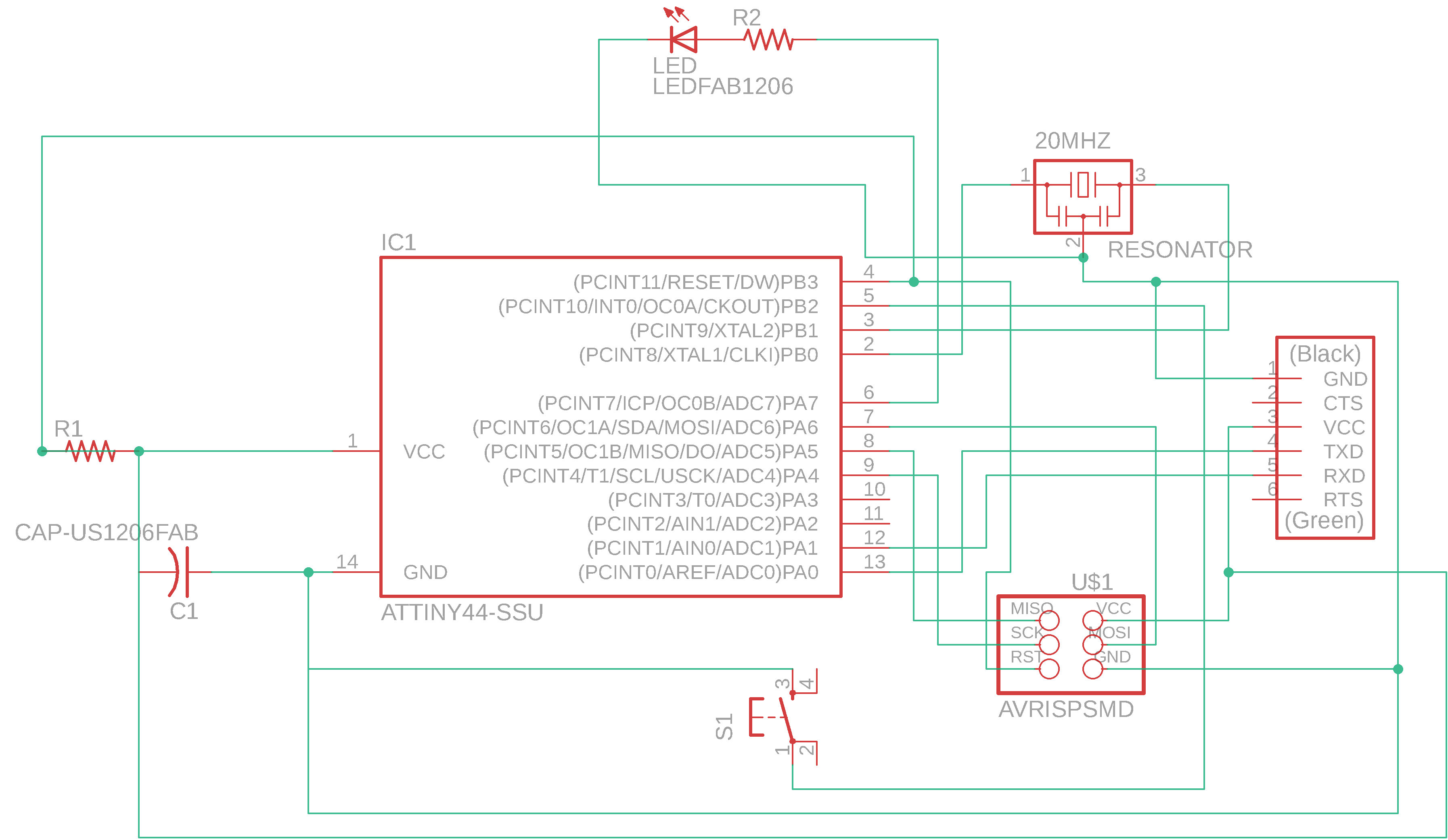
To begin the PCB design process, you will need to generate both Board and Schematic View. I started with "Add Part" function in the Board View and connected all components correctly by following this reference picture.

I added all the components showed in the picture, including an ATTINY44, 1μF capacitor, FTDI connector, ISP connector, 10k resistor, 20MHz resonator. For this week's assignment, we need to add a button, and an extra LED plus a 1k resistor to the sheet before switching to Schematic View. The final routing is as follows-
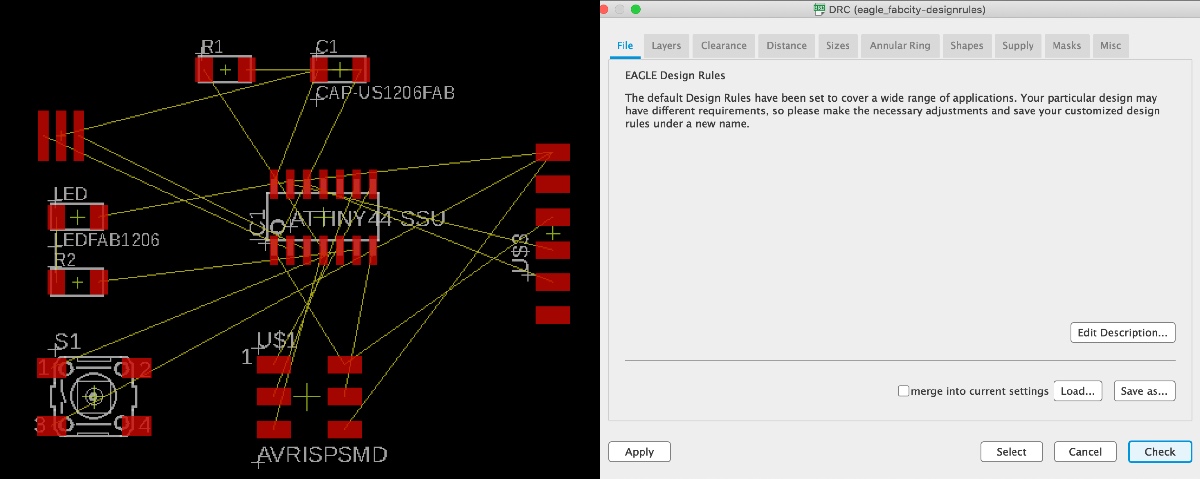
It's amusing to find a working circuit map from the chaos. I encountered difficulties at the beginning, but then I figured out that some lines should go through other components underneath. After solving the routing of the circuit, I import the "eagle_fabcity-designrules.dru" in the DRC tool to check if the circuit design does not conflict to the design rules.
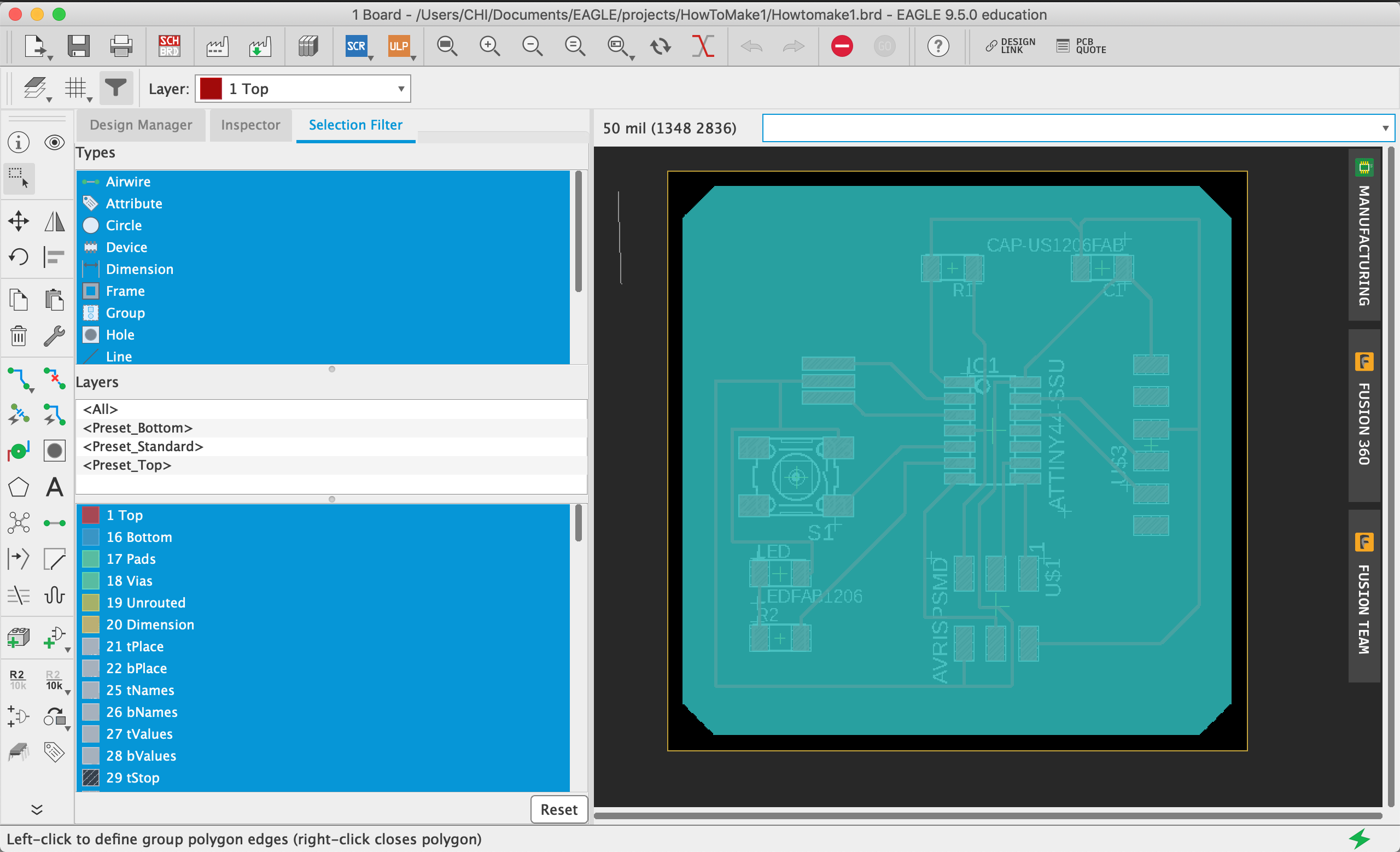
I added a polygon on layer46(milling layer) and narrow down the layer20(dimension layer) to get the outline to mill. I used the command "DISP NONE", "DISP TOP", "DISP DIM" to switch between layers. The final schematic sheet with all the layers showed up as shown below-
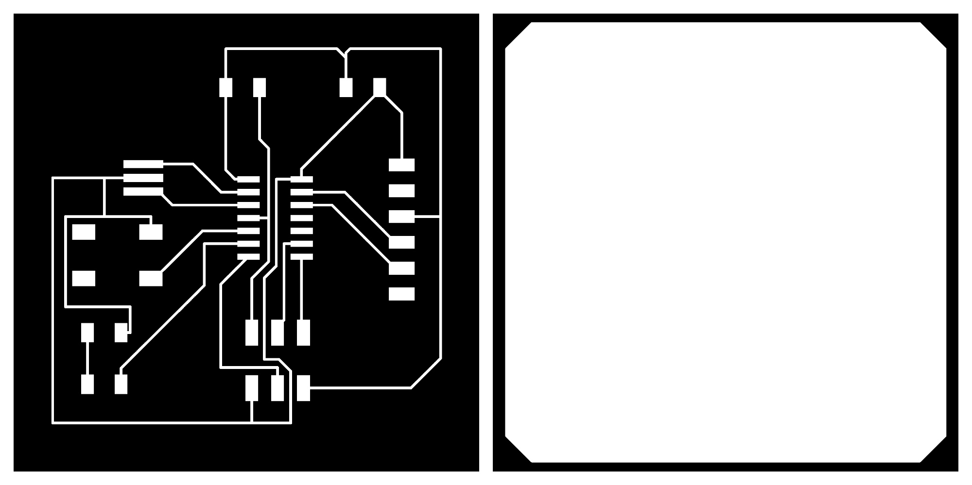
To export the PNG files you must make the Dimension layer(20) visible, while the one with the circuit routing contains the Top layer(1), and the other one with the board outline to cutoff contains the Milling layer(46). In order to run the python script, I installed XQuartz and Homebrew before installing ImageMagick since I was not able to figure out how to install ImageMagick on my mac with both official instruction and our gitlab document. Homebrew can install the stuff I need that Apple didn’t provide in the build-in system. After making some incorrect attempts, I typed and ran "brew install imagemagick" command in the Terminal and the ImageMagick was successfully installed. I followed the instruction here to generate the PNG files for milling. Make sure the size and the resolution are in the right settings. You can see the images I exported below-
Soldering and Programming

I made bad soldering this time. To test the programming part, you will need an FTDI cable, but it was difficult to find a spare one in the electronic shop for the CBA section most of the time.
Even though my soldering was terrible, but the programming part seems to be okay.

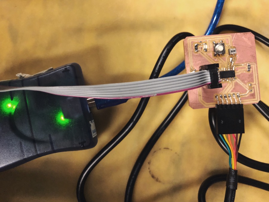
I followed the instruction from Joao and used a Linux system computer in the electronic shop. Firstly implement the program commands and then fuse it. The computer was able to recognize the board as a USB device, which indicates the board has been successfully burning. However, I got some problems when running term.py with the command "$ python term.py /dev/tty0/USB0 115200", which declares the port and speed.

I redesigned another PCB to test the echo function and serial communication. But I couldn't figure out if there were mistakes in my electronic design or just the lousy soldering caused them didn't work.
The FTDI cable is important since it transmit data with RX and TX pin in both directions.

I learned that the "Error 1" and "rc=-1" messages mean there are some problems on my board. Usually caused by the hardware design or soldering. I need to learn how to use multimeter and oscilloscope to fix the problems.

Week6Computer-Controlled Machining

This week's assignment is to test the parameters(runout, alignment, speeds, feeds, and toolpath) of the CNC and make something Big. We learned how to use the ShopBot router for cutting extensive material and got a bunch of 4'x8'x7/16" sheets of OSB to try out the assignment. These tools are useful for rapid prototyping huge cuttable material.
We were mainly using a 1/4" diameter end-mill during the week for cutting OBS. You need to use two different tools to fix the end mill to the Shopbot router.
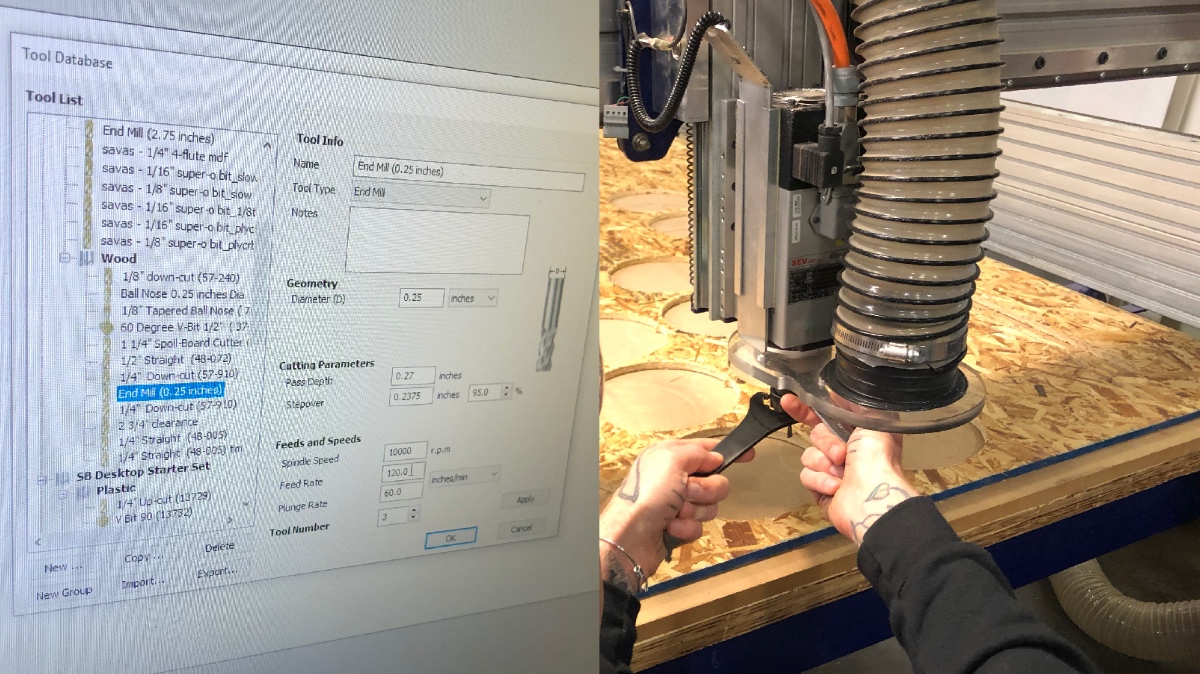
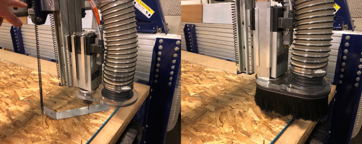
Before making the machine start to cut, we need to adjust the original point and remeasure the 0-point of the z-axis with a built-in metal plate. Remember to attach the hairy cover for the mill and open the vacuum.
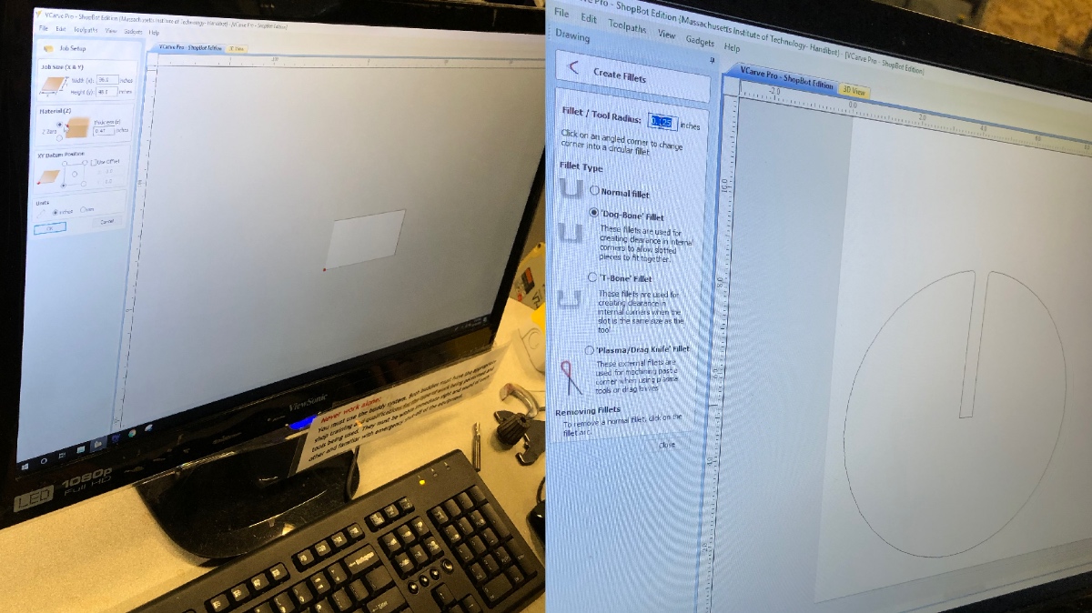
The choice of fillet types is crucial for assembling parts. Also, most of the time, you will need to set "tabs" to avoid the unexpected moving of cutting elements. Load the toolpath file to Shopbot software and activate the spindle.
For the group assignment, we practiced the operation of the Shopbot and tested several settings for CNC cutting and rastering.
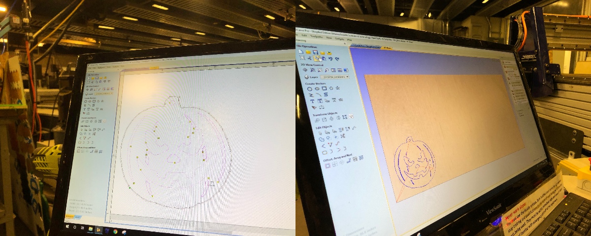
You can switch between the 2D and 3D views in VCarve to evaluate the design before export the toolpath.
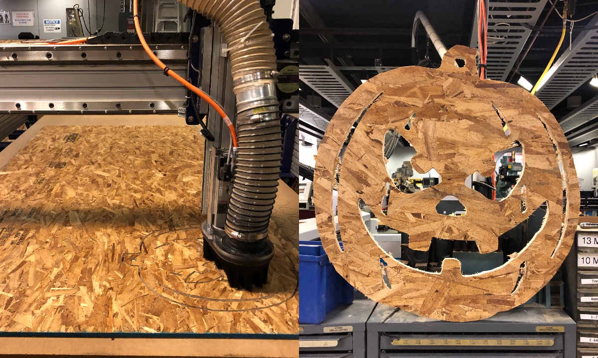
We finally got a milled pumpkin and a rastered ACT banner.

For the individual assignment, I used Fusion360 to draw the parts and do prototyping. After creating an assembly and arrange pieces as required, you can use the "Save As" option to export the drawing in the desired format. I exported .dxf files for each part to in my design and import into VCarve.

I added dog-bone fillets to the holes for joints. To ensure the milled size is the same as the initial design, we should set cut from outside for frames and cut from inside for holes. I tested the joint with smaller parts before cut through the whole piece to avoid wasting material.
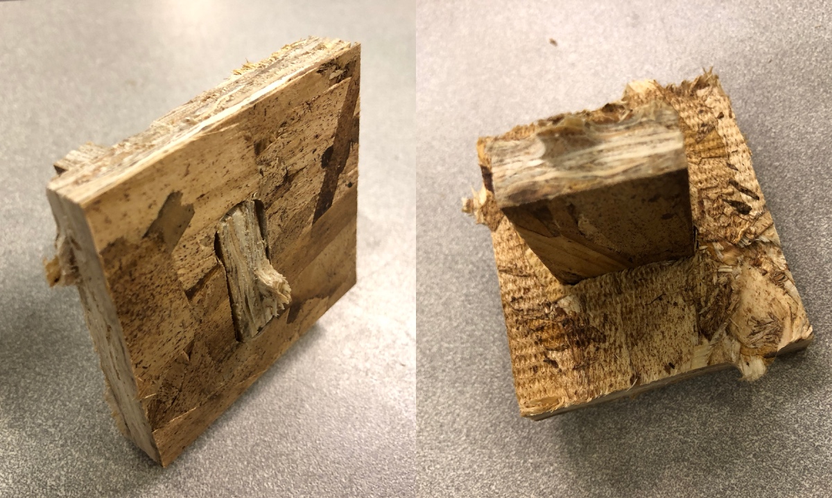
The time slots I booked was over when I finished this small table.
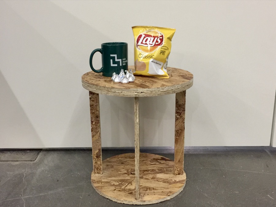
I actually made another design for a more massive desk. However, I didn't get the chance to use the Shopbot again this week. Might give it another try in a couple weeks.

Week7Embedded Programming
The assignments for this week were to read through the datasheet and to program a new board doing something with additional components.
Board
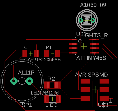
I was thinking of making a light-controlled noise generator with an Attiny45 microcontroller. The input is the light, so I need an LDR (Light Dependent Resistor), which decreases the resistance with increasing incident light intensity. The output is the sound of ticks and clicks so that I might need a speaker. Overall the components I used include:
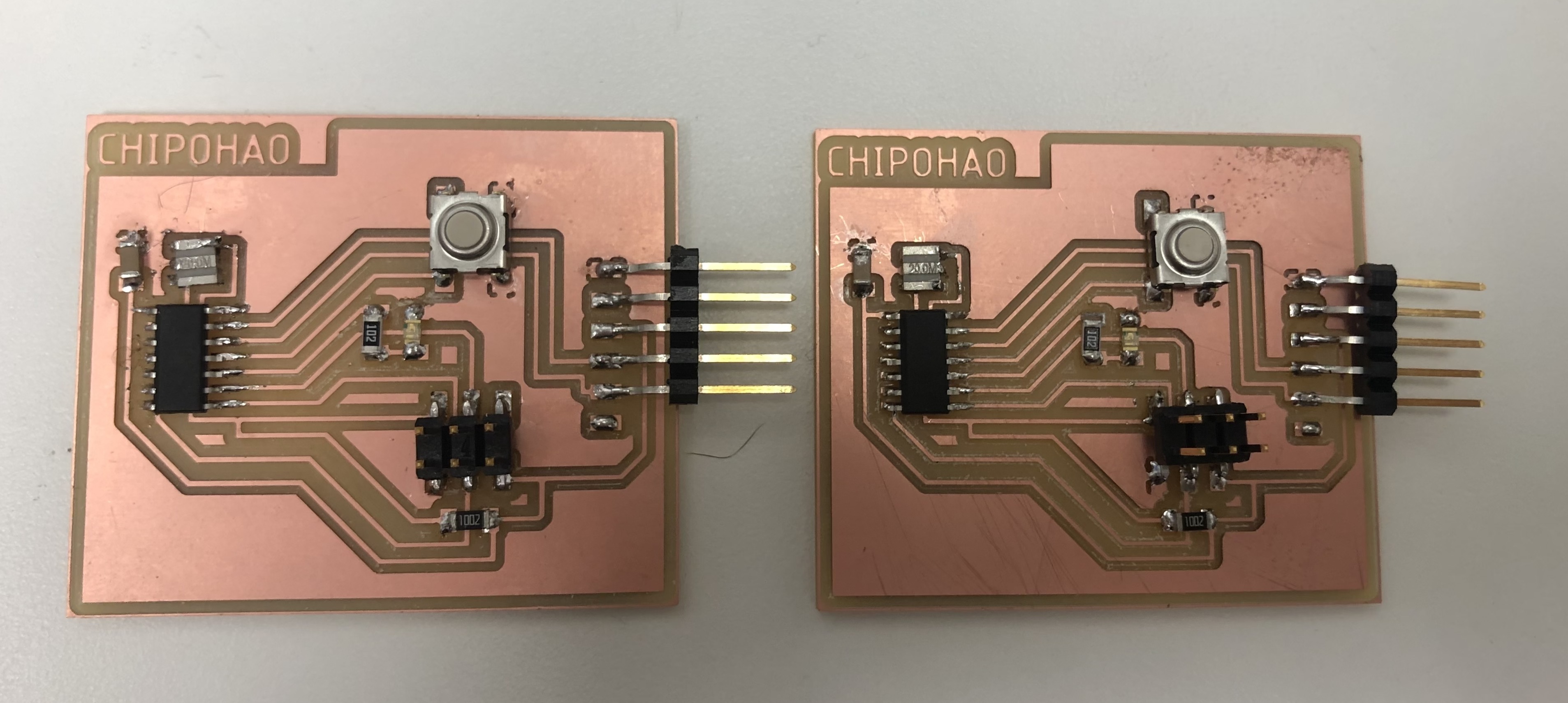
I designed the PCB with all of these components as pictures below.

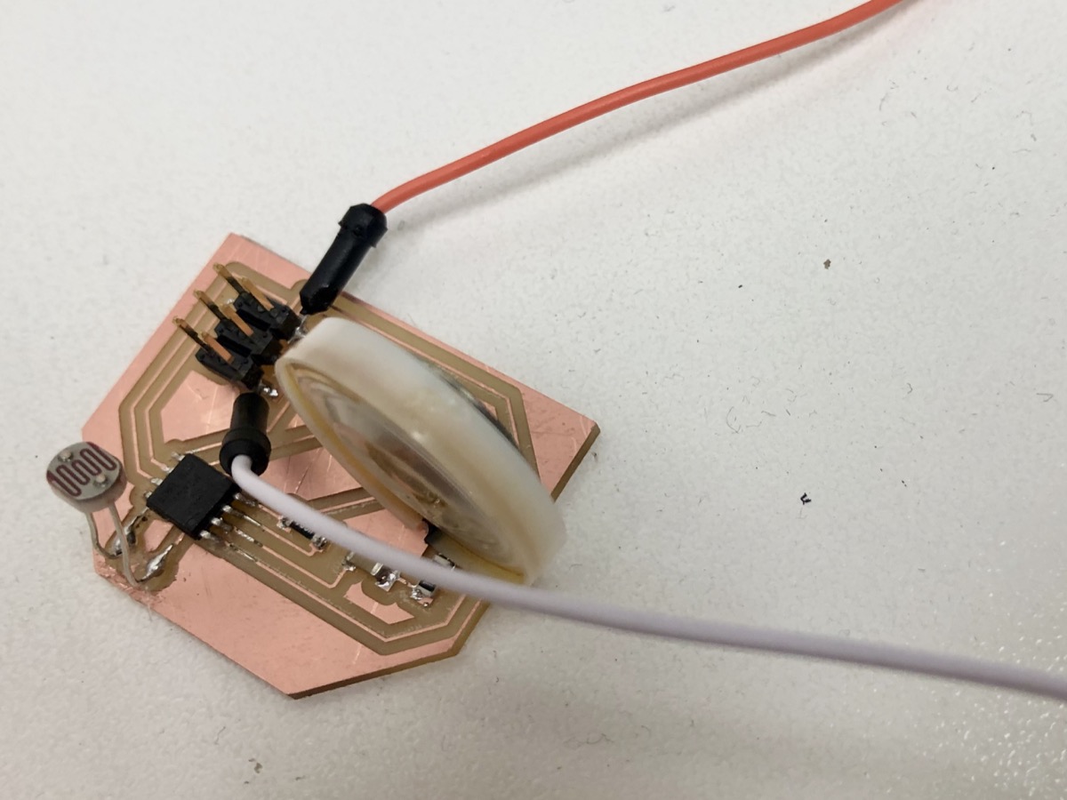
I tried to drill the holes but failed. Don't know how to export the PNG file with the holes.

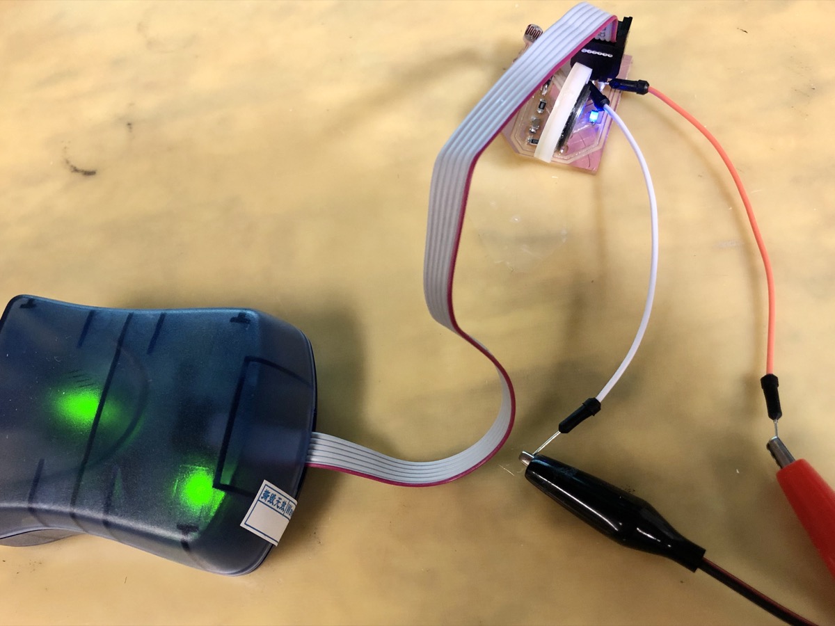
However, I finally got my board and soldered everything on it. I didn't put the FTDI connector on the board so I soldered two external wires for supplying the power.

Program
I installed HomeBrew a few weeks ago on my MBP, so I was typing "brew install avrdude" to run the avrdude commands.
There are two numbers for the input in this PCB:
So I tried to read the input value and comparing it to the former input value giving me the difference:
"valueADC = adc_read(3);diff = abs(valueADC - valueADC_old)". Thanks to Erik's office hour, he explained the basic of signal processing in C and helped me to review my code.
Now it was time to see if it was working or not. In the beginning, I cannot find my programmer in the terminal. Not sure if I typed the wrong command.
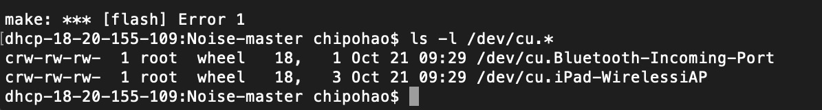
And when I tried to "Make flash," it just didn't work. I kept getting the rc=-1 issue over and over again.
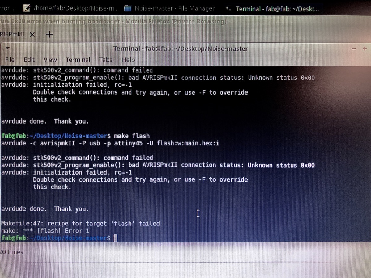
I checked with the multimeter, but the voltage and current seemed to be in reasonable values.

I found Ben's useful checklist on the class website. I might follow this checklist to figure out what's wrong on my board in the next couple of weeks, or just make another board to get a functional PCB.
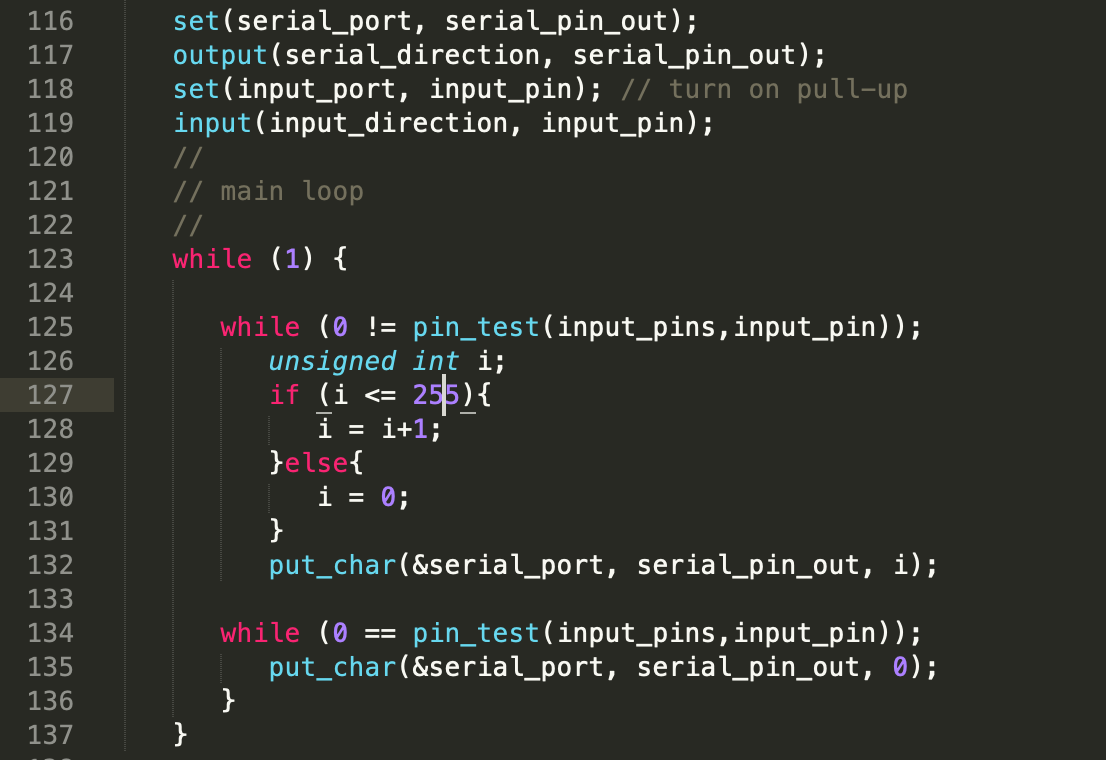
Update- Counting button pressed time
I modified and programed a button board to make it count the time I pressed the button. I used Max to receive the result and showed it on the screen. Below is the code I added to the C code file.
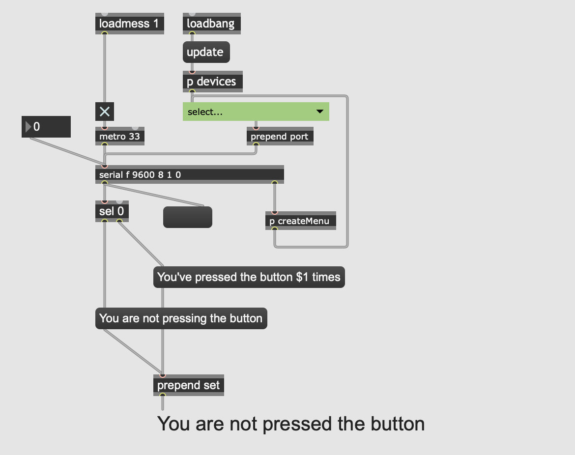
Here is the screenshot from Max. It only used the number receibved from the button board to replace the $1 variable.
You can see the result as the video below.