Thin Film Microphone
Electronics
This is key circuit to get the sound from the piezo sensor. My amplification circuit uses as AD8253 amplifier and UAF42 filter to get a clear audio signal from the piezoelectric sensor. My current implementation uses a -6 / +6 volts power supply with a center at 0V. The AD8253 is set to a 10x gain on the signal and the UAF42 set as a high pass filter with a cut of frequency of 200Hz. This board doesn't include the ADC yet. My plan is to use the ESP32 as my ADC board.
Board v1
For this first model of my board I decided to work with amplifier that I had been working so far and implement a one channel version of my amplifier. The board characteristics are +6/-6 (dual supply) and using a instrumentation amplifier AD8253 with a UAF47 filter as a high pass. The piezo signal goes into the differential input of the op amp and has a filter stage (high pass).
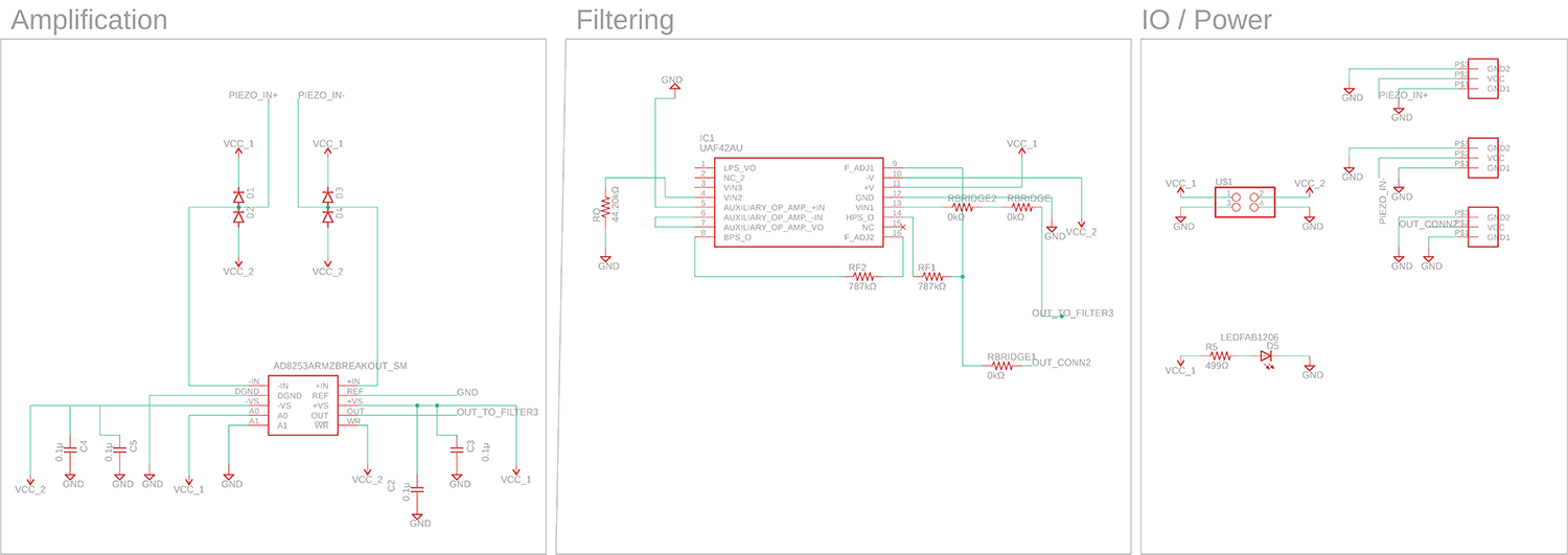
This board worked really well but it is overkill for what I need. The voltage level of the microcontroller (SAMDD11) is 3.3V whereas my pkpk at the moment is 12V. I also require to use a dual supply (+/-) given the technuical specs of the UAF47 filter. And the footpring of the AD8253 (MSOP-10) can't be milled with our Roland SRM-20 machine. I also don't like the bulkyness of my current connection strategy.
Here is me moving the paper using different levels on the volume. You can hear some distortion there and my suspicion is that the sensor (that has an unshielded electrode) is capacitively coupling to itself as I giggle the paper.
More testing with moving the sensor to get a singal, it sounds super clean and without any interference from 60Hz
Here is me moving the paper using different levels on the volume. You can hear some distortion there and my suspicion is that the sensor (that has an unshielded electrode) is capacitively coupling to itself as I giggle the paper.
This led me to design a V2 of this board, using a different opamp (that has similar characteristics to the 8253) that can be single supply powered and sourced in a SOIC package for ease of handling.
Board v2
Requirements:- Performant in audio range (20Hz-200Khz)
- Single supply(ideally 0-5V) - facilitate leveling with DSP chip
- High impedance input (for AC signal from piezo)
- Minimum gain of 10x and maximum of 100x (for my long term plan I use the audio interface as a secondary gain stage).
- Controllable gain
- Ouput for analog signal
- Integration of SAMD11 Some options I looked at:
AD8253
4Mhz Bandwidth (G = 10)
CMRR: 100 dB at G = 1000 (DC to 20 kHz)
Package: 10-lead MSOP
Observations: the strength of this opamp is the fast gain change through high/low pins which is a feature I don't use. It also has a high CMRR at high frequencies. GBP is way above what I require for my application Challenge is the package (MSOP) which I can't mill which makes it hard to iterate.
AD8220
800KHz Bandwidth (G = 10)
CMRR: 90 dB at 5 kHz for G = 10.
Package: MSOP-8
Observations: This has a lower GBP and a CMRR similar to AD8253 and can run on single supply but the package would still be a challenge.
AD8221
562 kHz Bandwidth (G = 10)
CMMR 80dB at 10 kHz G=10
80 dB minimum CMRR to 10 kHz (G = 1)
Package: t 8-lead SOIC and 8-lead MSOP
Observations: this seems to be a good candidate. Available in SOIC package with a acceptable bandwidth
at G=10 for audio application.
Board v2 Design
My strategy for designing this board was to use the instrumentation amplifier AD8253 as the input from the sensor given it's high impedance. The AD8253 can change switch the gain using logic voltages (0-5v). It can be set to a gain of 10x,100x,1000x. For the gain selector I added a switch.
I added a filter stage and a second gain stage with variable gain that can be set using a trimmer.
1. First stage gain
2. Filter
3. Second Stage Gain
4. Scaling (from 5V pkpk to 3V pkpk)
Given I wanted to achieve high sensitivity and low noise on my board I opted for conditioning the microphone signal from the piezoelectric sensor through a high pass filter and an instrumentation amplifier.
For the analog filter I designed a 2nd Order Sallen Key filter with a cut off frequency of 200Hz and a roll off of -20dB. To do so I used a design tool provided by analog devices to help me calculate the components values and frequency response of my filter
I also opted to shift my signal from the sensor from a 0V center (DC coupled) to a 2.5V center. For this I had to build a bias circuit to provide the reference voltage for my filter.
This is the amplification stage of my circuit where the sensor inputs and this amplifier outputs the signal with added gain to the second stage of my circuit that is a high pass filterfilter
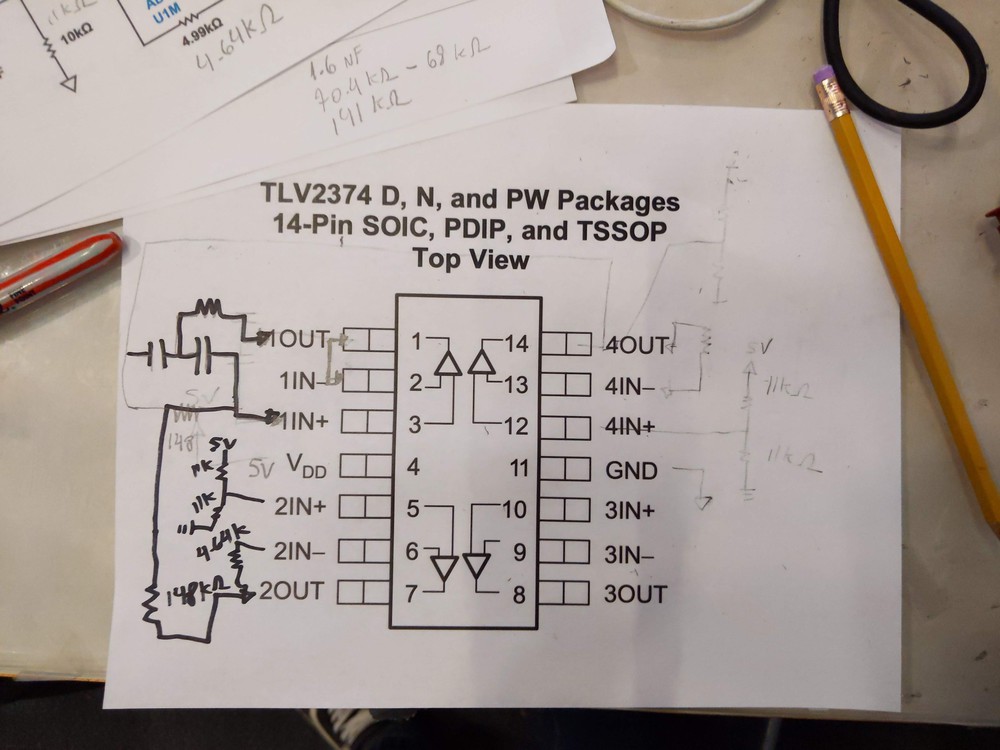
Using the TLV2374 quad amplifier I coupled the filter (opamp1), bias voltage buffer (opamp2), second stage gain (opamp3), scaler (scaling output signal from 5V to 3V for microcontroller) for both the bias voltage and scaling I designed a circuit based on a voltage divider with a buffer stage at the end using the TLV2374 op amp.
Last stage of the circuit it inputs on A4 pin of the SAM11C for sampling. I also added an analogic output for headphones in case I wasn't happy with the sampling quality.
Board v2 Prototyping
I started my design with the most hard part which was to combine the filter, second stage and two buffers into one quad op amp. Here is me planning how to allocate the pins to the different components.
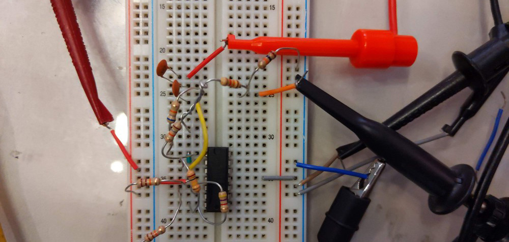
Given the complexity of the circuit and the number of resistors and capacitor to tune the frequency I decided to prototype on breadboard first, in this way I could get a real feel for how it would work and test my schematic.
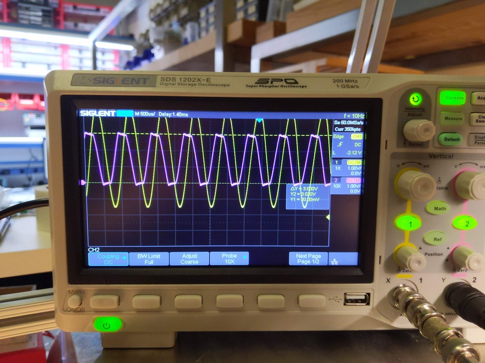
Here is a me checking the response of my filter at frequencies around 600Hz. The purple sine wave represents my filtered signal and the yellow the unfiltered. This shows the filter was respoding well
Watch the amplitude increase as I increase the frequency in the function generator
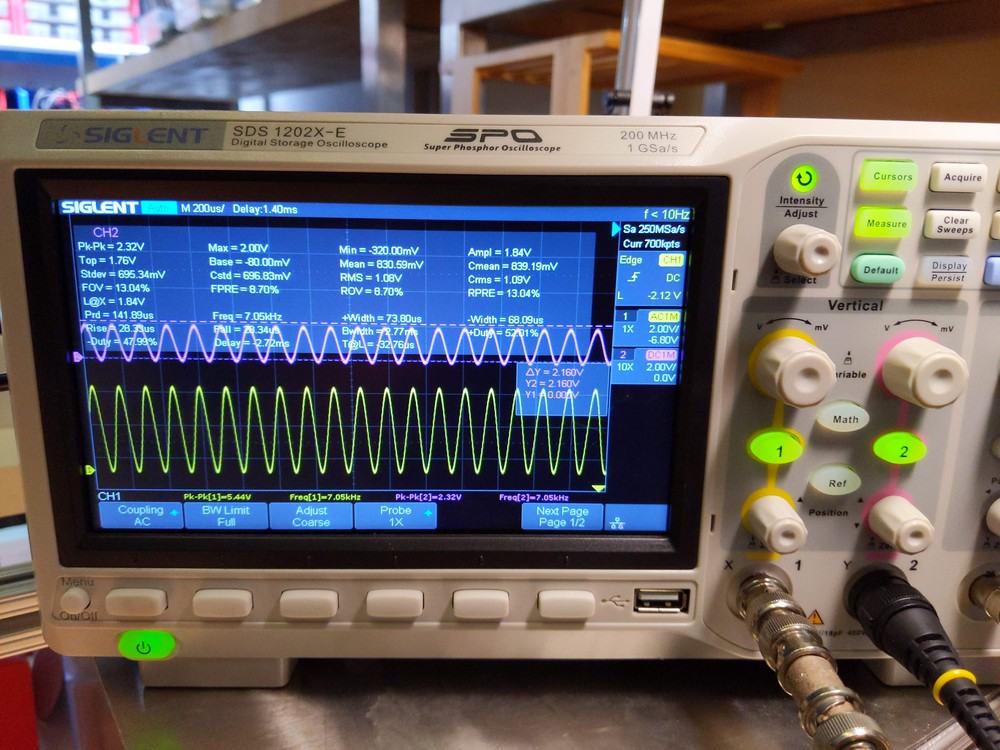
I also made sure that the circuit wouldn't present to high of a voltage on the microcontroller analog port by using a divider to scale down the voltage. Here you see the voltage 'railing' at 3V if the amplitude of the signal his higher than 3V.
This is the final rig of my circuit. It works well so I then moved on to design a board that can be milled.
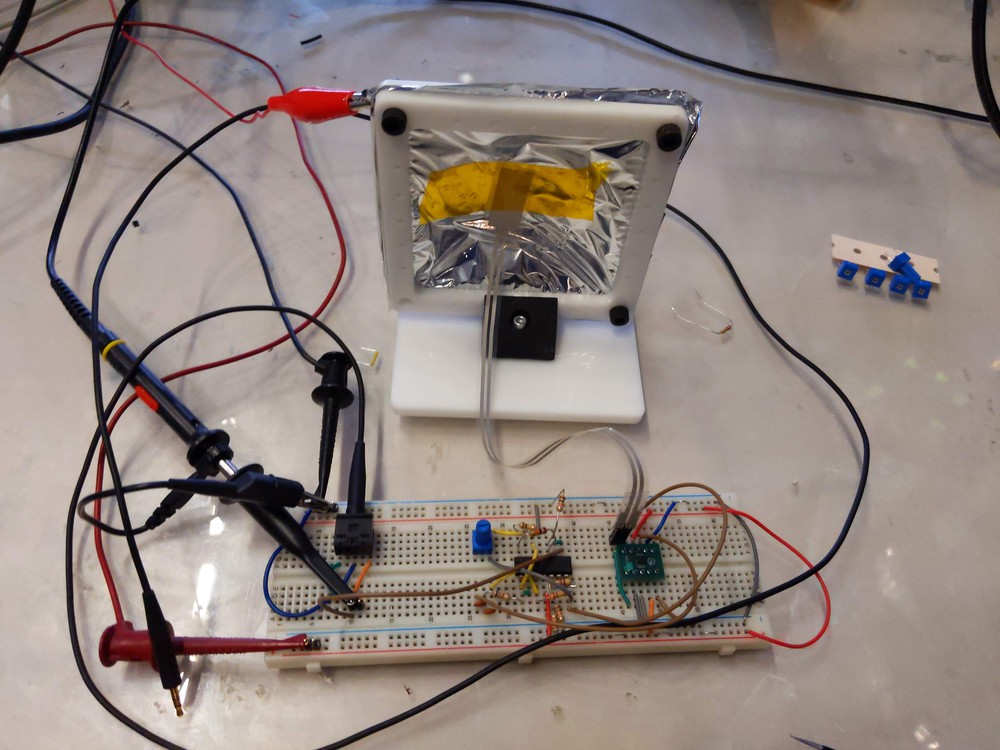
Turn the sound on to hear this tests, the piezo microphone is highly sensitive and can pickup sounds from the room well as objects that fall on the table.
Board v2
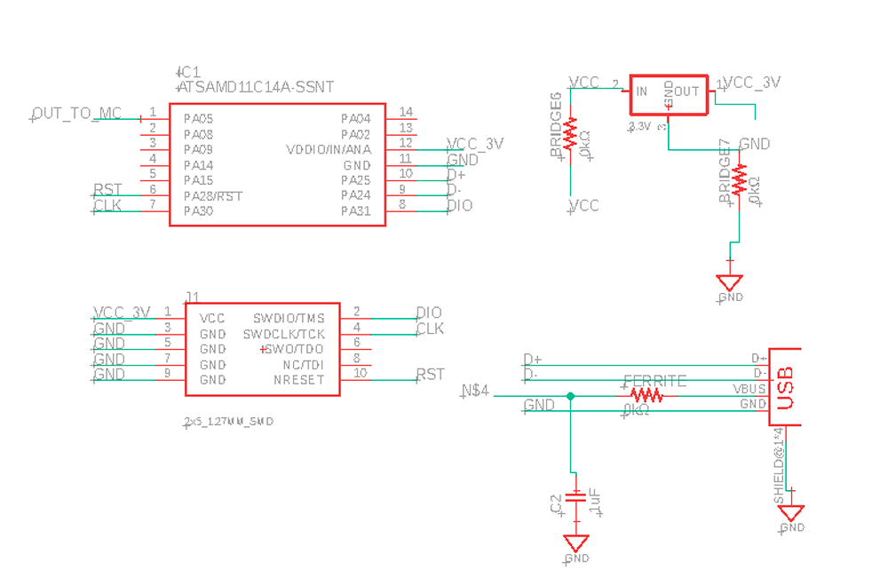
I then started the design of the board in eagle. My core components are the ones below:
AD8253 amplifier
Trimmer 10kOhm
TLV7234 amplifier
Dip switches amplifier
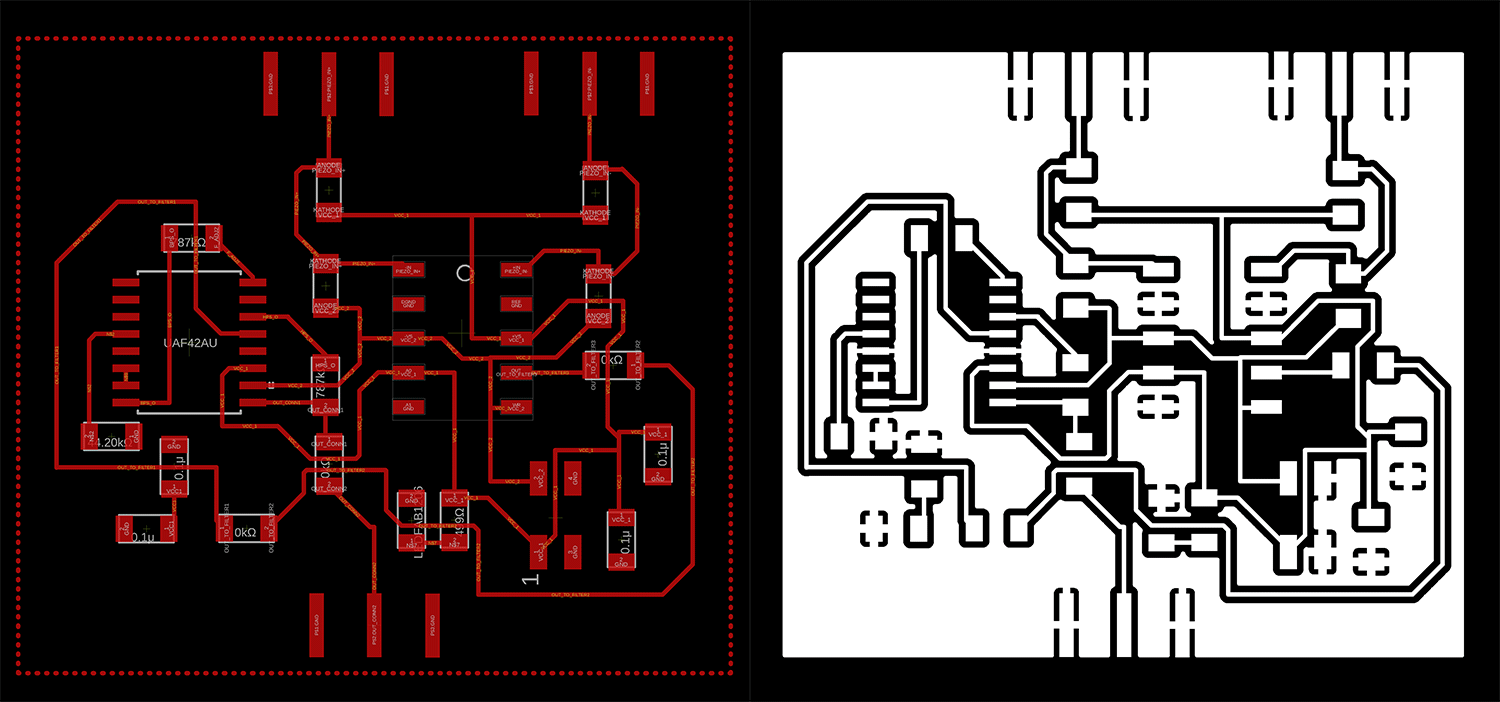
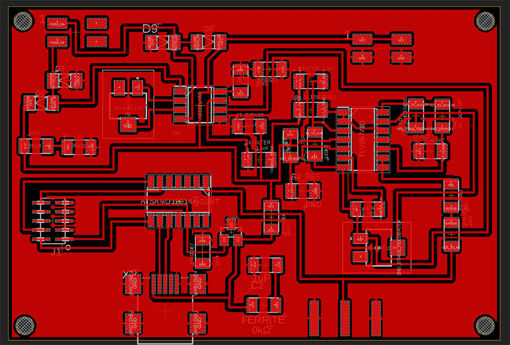
After a few hours moving compoents around I manged to fit all in one layer using a few 0kOhm resistors as bridges. I just need to adjust a few areas around the JTAG connector, do a final check on resistor values and I am ready to do a first mill of the board.
Here is the final design of my board, I decided to use the USB micro as a connector to the SAMD11 and leave an extra power pin in case USB doesn't have enough current.I managed to keep all the traces in one layer using a lot of bridges (7 currently), I still prefer that over having to do a double sided board.
The board turned out to be much larger than what I expected but this is good enough for now as a test, if this works well I might try then to optimize the size of the board
To drill the holes my strategy will be to use the 1/64 mill but change the configuration of mods to 1/32 so I can get the correct cut depth to go all the way down the board but still use the 1/64 mill
Board v2
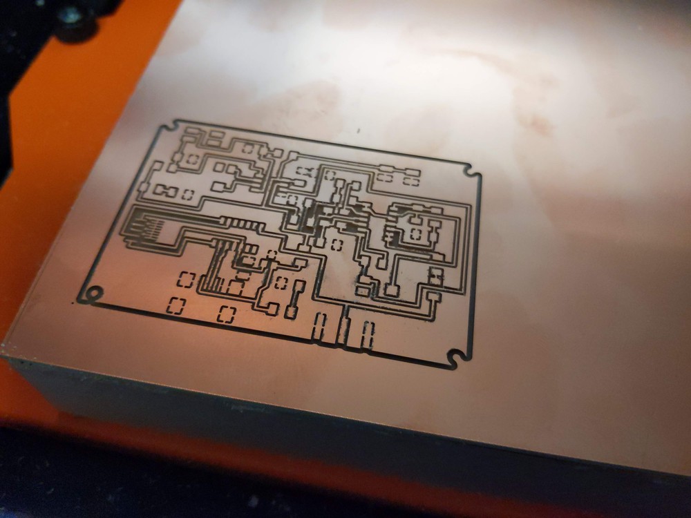
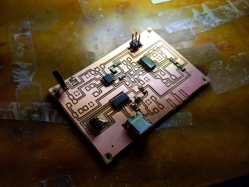
Started by doing a test and milling the board, the size was a little larger than I expected but the board turned out OK, i decided to use through hole components for the trimmer and switches (given they are interacted with by the user), to give the components more stability I decided to add rivets to the board
Started by doing a test and milling the board, the size was a little larger than I expected but the board turned out OK, i decided to use through hole components for the trimmer and switches (given they are interacted with by the user), to give the components more stability I decided to add rivets to the board
Now my next step will be to stuff the board with the components, given the number of components and things to go wrong, I will build and test stage by stage, starting by the power and the first amplification stage.
When testing the board I encountered some issues pertaning to noise. Whereas in my breadboard prototype I had a very low noise level, in my milled board I could hear 60hz noise and when using the USB a digital high frequency switching noise.
To eliminate the 60hz noise I decided to make the wires shorter and go directly from the sensor connector to my board - without the SMB connectors. I made an attachment that ccould serve as the connector (with the idea in mind that I would mill and stuff a new board).
Another strategy was to connect the ground of the board to milar layer as a shielda
Problems when testing:
- The board overall works well - I could hear the amplified signal from the headphones and see the data in the serial port from the SAMD11 - One issue was RF noise coupling through the circuit and noise in the power lines. Brian advised to add more bypass capacitors, perhaps stacking them and putting them as close as possble to the power lines of the board. - Another tip was to mill a double sided board and put a rivet to the bottom of the board where there's a large ground plane to act as a shield to the electronics. - To mitigate a high frequency noise from the USB power Brian (and Neil) suggested adding a lowpass filter to the power line of the USB. - I wasn't really happy with the level of noise on board v2, in a long consultation session with Brian M. (thank you) he gave me a few advices. The AD8253 isn't intented to be used in a single supply configuration, this could be causing the amp to misbehave and not apply the gains correctly.<Board rev 3 - AD8221
I then went back to Eagle and designed a new board, now using the AD8221 Changelog:
- - Using the AD8221 (single supply amp from Analog Devices)
- - Surface mount precision trimmers
- - Highpass filter on the USB output
- - Easier to handle input connectors to the piezo sensor
- - Filter and second stage remain the same.
In the new board design I used the AD8221 without the need for a breakout board which made the board easier to design, I also changed the footprint of the trimmers to be surface mount precision trimmers
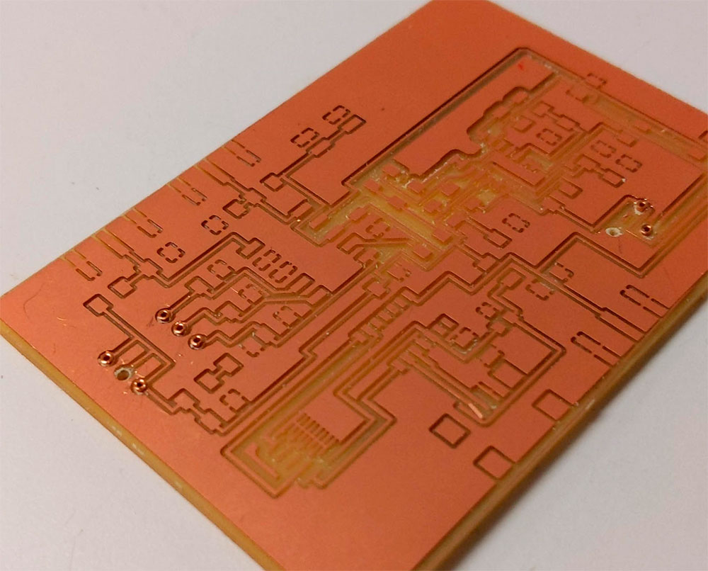
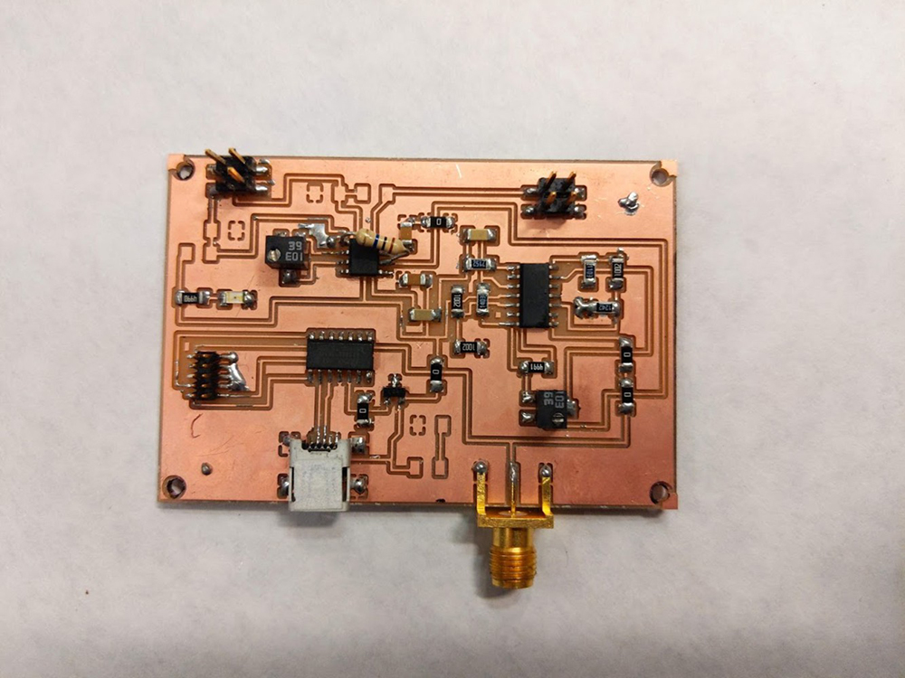
I milled the board without any issues, the traces were sharp and clear without any need for deburring. I had to do the milling in two stages, one for all traces with a 1/64 mill and a second stage for the holes. Brian recommended for me to use a double sided board and have 2 rivets tthat connect the top to a ground plane at the bottom.
In the new design the size of the board also reduced as I used surface mount connectors as opposed to the SMB connectors I had been using before.
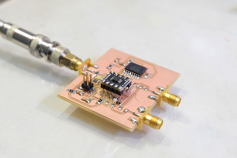
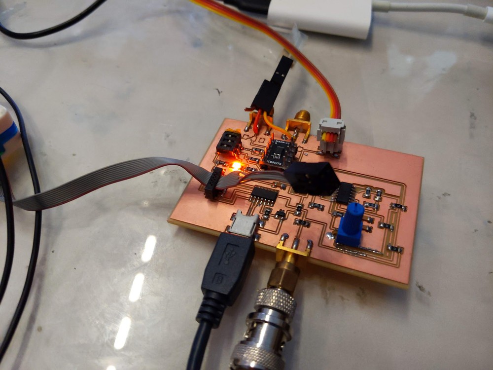
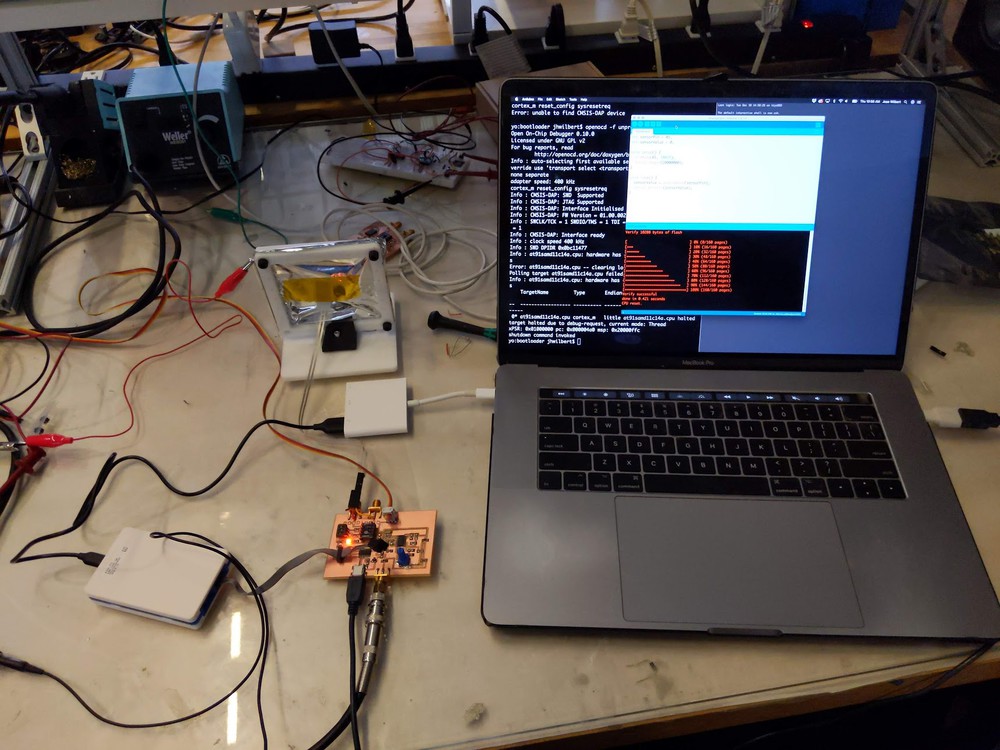
Given the size of the board and number of components I had to carefully stuff the board in stages, I first started by adding all ICs (instrumentation amplifier, quad op amp and SAMD11) I then checked if all had power with a multimeter, I then checked if I could program the SAMD11 via USB. Only after I checked these items I went on to finalize the stuffing of the board with the resistors and capacitors - it took me around ~5 hours from milling to have a finalize board.
.
After assembling the board I had huge issues with noise, I could only hear very high distorted noise coming from the sensor when the board was connected. In a session with Brian, he helped me debug it and the reason for the noise was that both pins are floating when there's no connection, and the instrumentation amp is amplifing that different. So he advised me to add a 10MOhm resistor across the two pins of the input (piezo- and piezo+) and connect another 10MOhm resistor between the negative pin and ref of my amplifier
.
In doing so I could massively reduce the noise and the board started behaving with a very clear sound when testing with different piezo sensors.
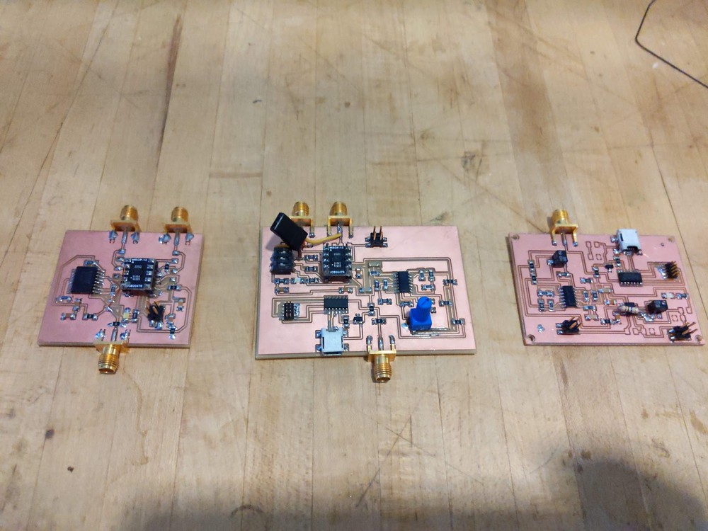
As a closing image for this section here are the evolution of boards I designed and made, the first just amplifies the signal with one op amp and uses a filter IC (UAF 42), the second iteration uses the same amplifier from the first (AD8253) with a filter that I designed but still relies on an external ADC. The last board has two op amps and an integrated adc (using the SAMD11) and can be power by USB.