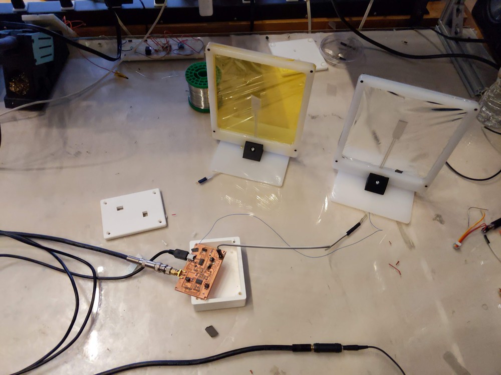
Thin Film Microphone
Stand / Board Enclosure
Sheet Stand
I decided to make a stand for the sheet microphone to be applied, in this way I can experiment with different paper thicknesses and other materials such as mylar. I decided to make the stand out of laser cut perspex for the frame and base and 3D print the feet. I used Fusion 360 to model the stand.
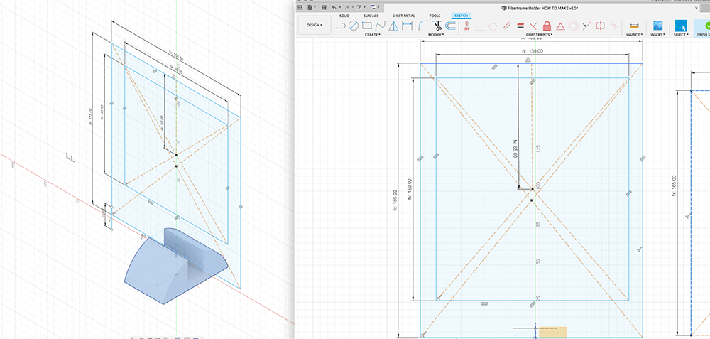
I started exploring different dimension, first starting at 10cm by 10cm for the frame, but decided to make it larger (the more surfacce area of a vibrating membrane better acoustic coupling.
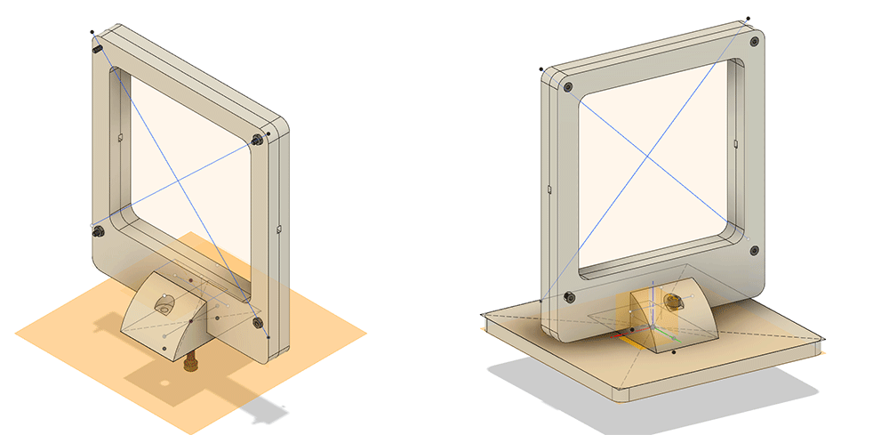
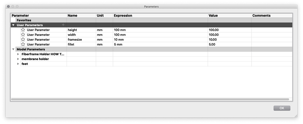
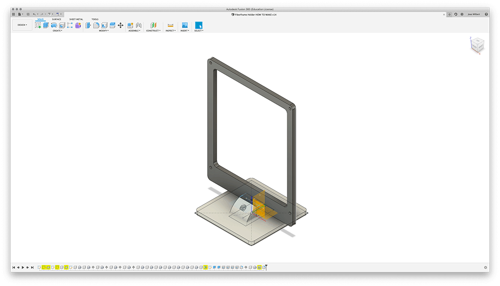
I made the model parametric so I could easily vary the height and width and both the base and position of screws to the adjusted height and width in the parameters, centering the design and keeping the feet at the same position. I also used the integration with McMaster Carr to import the screws and test their fit in the frame.
Here is a final image of the modeled stand before rendering. I have to say that I still struggle with the idea of timeline and features in fusion. If you start a sketch and build body in the correct way there's no problem, but if you need to go back and make changes - like moving a part from one position to another, editing on the volumetric space starts disconnecting the model from the sketches which isn't ideal.
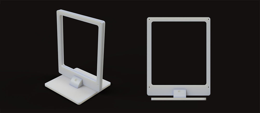
I then used the fusion renderer to render my frame in the color of material that I acquired.
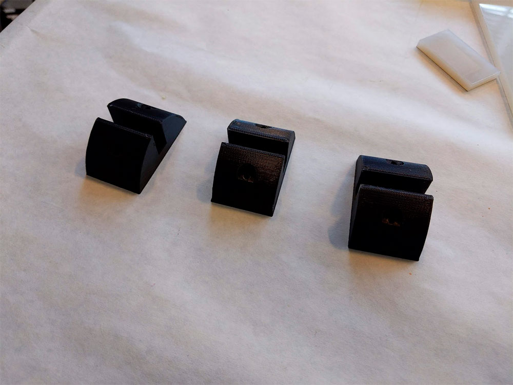
Here are some images of the feet that I will 3D print, for now I might just use the FormLabs printer in TMG as I want this to be on a slighly flexbile resin so I can tight fit my frames on to it.
After modelling the frame I outputted the files as a DXF for the laser cut parts and as a STL for the 3D printed feet. My next step now will be to laser cut the parts for frame and base, 3D print the stand foot and assemble the parts.
Making
To make the stands I exported a DXF from Fusion360 into Corel draw, I wanted to use engraving to create a lower profile to have flush screws on the screen and carve the bottom of the frame with a lower profile so they can snap fit into the feet. In order to do so I carried out a number of tests with different power and speed to find a 0.5mm profile.

I used color mapping on the laser for vector and raster, the bits in red are the raster cuts to carve the profile (subtractively) and the parts in green are the vector cuts that cut the outline of the form.

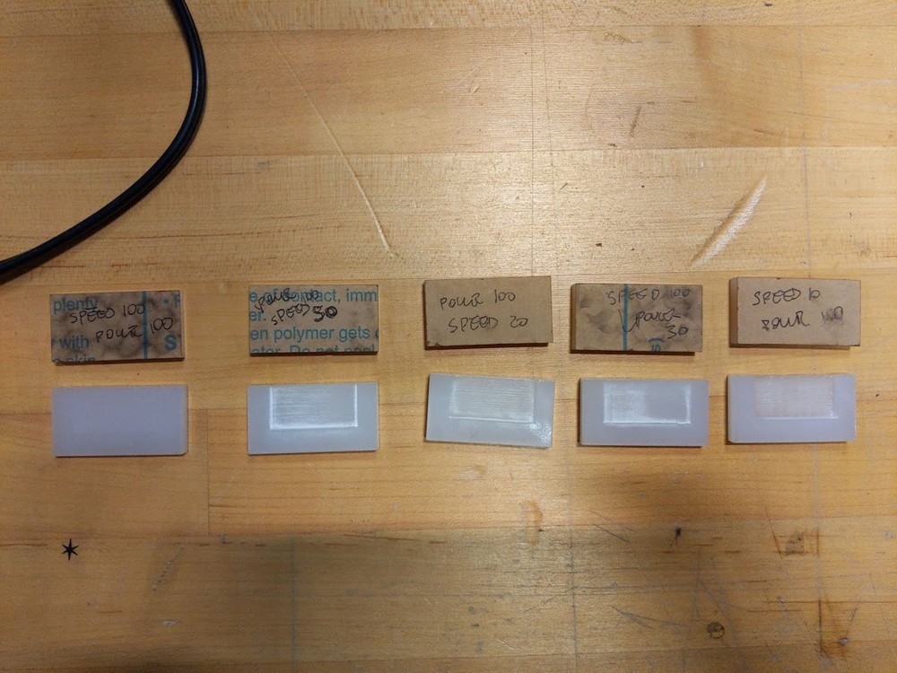
This tests took me a while to do sine the raster cut isnt't very fast, but after doing them I could precisely define the profile I wanted for the tight fit and then just replicate that cut across my multiple frames.
After a few hours tweaking settings I started to get some good results, here's a test using the 3D printed feet and the laser cut frame
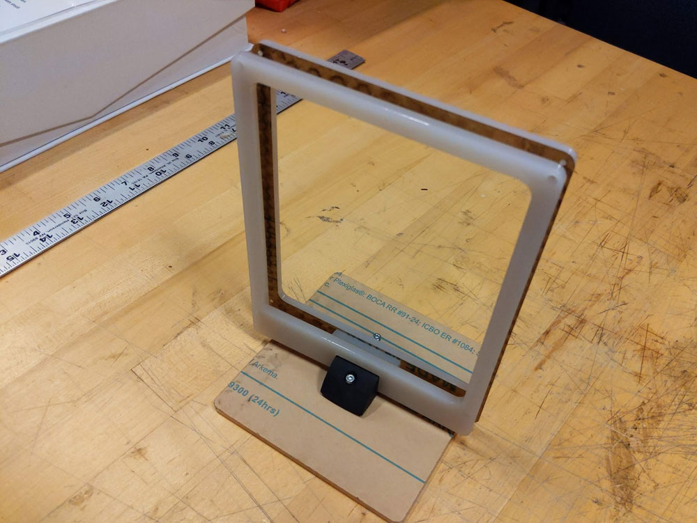
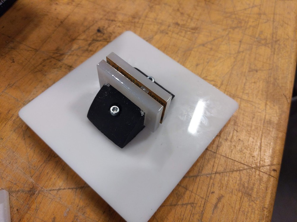
Here is an image of my test, in this case the gap on the feet was to large but the idea of the lower profile on the frame helped with stability
.
The next step was to 3D print the feet, for that I used the Prusa Printer, I exported the STL file from Fusion360 and used the PrusaSlicer to create the 3D print job. The job took about 5 hours to be fully printed. We left it running overnight and when we came back on Sunday morning the print was done!

The next step was assembly, I started putting together the frames with the film, Jack gave me a good tip to use double sided sticky tape on frame to stretch the film which helped a lot. After the parts were laser cut I had some issues with the fit, some of them wouldn't snap very easily - this was probably due to tight tolerance. As a workaround I used a dremel to shave of the parts I didn't need.
Board Case
I also designed a case for the board. To do that I exported a DXF of my board from Eagle into Fusion (I had to do a cleaning job in Illustrator as the DXF exported by Eagle was crashing Fusion), after a long cleanup job I had my board footprint in the CAD model. I made the box dimensions parametric so I could tweak and test it.
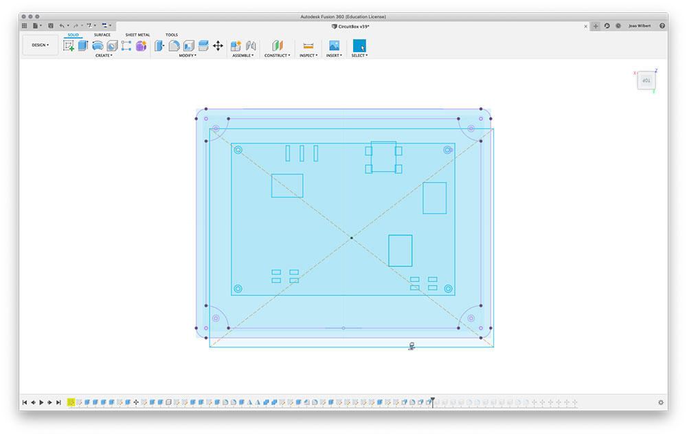
I left some open spaces on the lid so I can access my gain stages with a screw driver, the gain change is not supposed to be a user feature but more a setup, so I didn't mind concelling them.
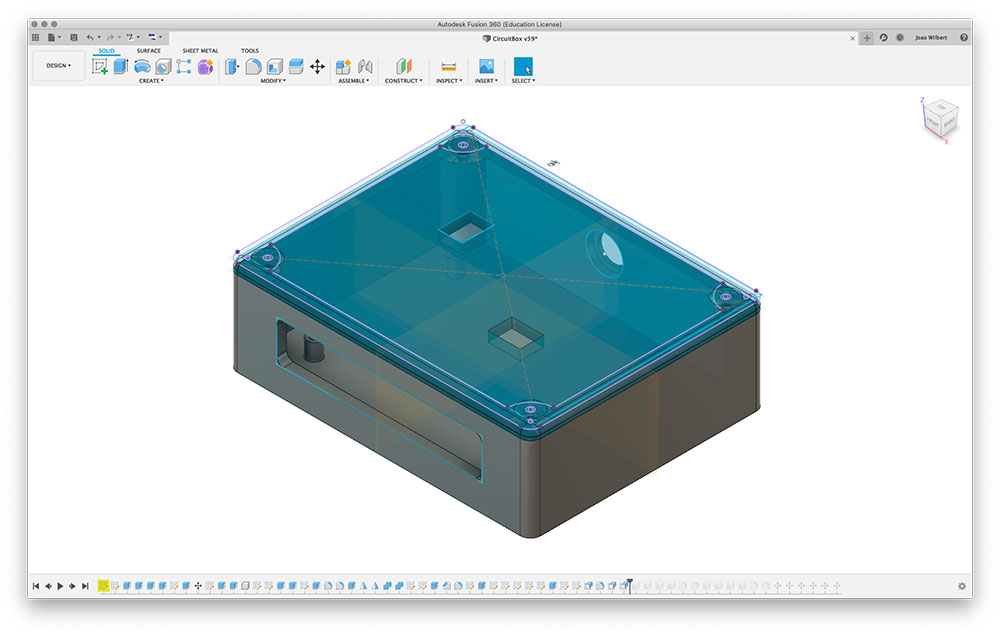
As with the stands I decided to 3D print the case using the Prusa 3D Printer. This is my first prototype of the box. Alfonso gave me a hand in checking tolerances and spacing. The issues I identified where that the walls were too thick and the board was too far from the USB opening so I couldn't access it. I then tweaked my model and rexported and it's being printed right now (as I write the text).
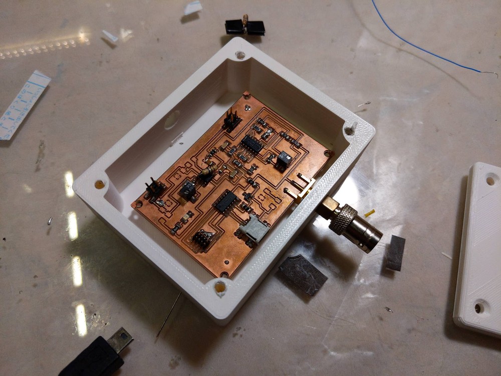
Apart from these snags the board and stands were ready in about two days using LaserCutting, 3D Printing and milling with the laser cutter to get the profiles.
