final project: fab-scale
 For my final project, I designed and fabricated an open-source analytical balance I'm calling Fabalance. As discussed in Week 1, analytical balances are a crucial scientific instrument that as of yet has not been reproduced in the open-source science community. Most chemistry and biology labs have at least one decent analytical balance, easily identified by the sliding draft shield and prominent spot on the bench. Unlike common scales, analytical balances don't use load cells; instead, they use an electromagnetic balance mechanism with an optical feedback loop, inferring mass by the power required to keep the weighing dish from moving.
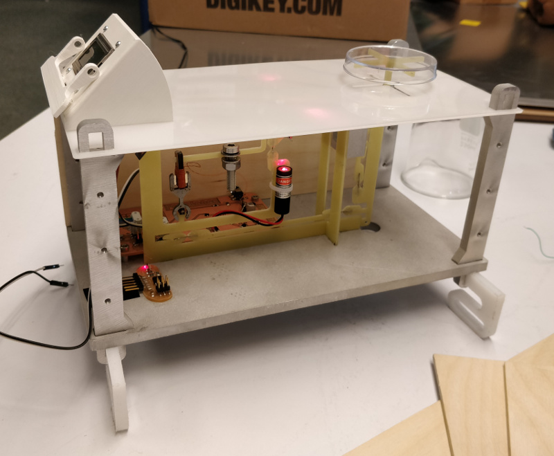
So, did it work? Short answer: I didn't get up to weighing anything, and crucially I never closed the control loop between the electromagnetic actuator and the optical sensor. But all of the subsystems worked, and the overall integration and packaging of the instrument can be considered a qualified success. Importantly, the learnings of the last Fabalance iteration paint a clear path to the next steps in the project, which I hope to take after I catch up on sleep.
Many people helped support this project along the way. In particular, I'd like to thank Alfonso, for helping fabricate a number of aluminum parts on the CBA water jet cutter; Jiri, for suggesting the AFM-like mirror-based optical feedback mechanism; Jake, for helping steer me back from a few deep rabbit holes; and Danica, for putting up with week after week of late nights at the lab.
For my final project, I designed and fabricated an open-source analytical balance I'm calling Fabalance. As discussed in Week 1, analytical balances are a crucial scientific instrument that as of yet has not been reproduced in the open-source science community. Most chemistry and biology labs have at least one decent analytical balance, easily identified by the sliding draft shield and prominent spot on the bench. Unlike common scales, analytical balances don't use load cells; instead, they use an electromagnetic balance mechanism with an optical feedback loop, inferring mass by the power required to keep the weighing dish from moving.
So, did it work? Short answer: I didn't get up to weighing anything, and crucially I never closed the control loop between the electromagnetic actuator and the optical sensor. But all of the subsystems worked, and the overall integration and packaging of the instrument can be considered a qualified success. Importantly, the learnings of the last Fabalance iteration paint a clear path to the next steps in the project, which I hope to take after I catch up on sleep.
Many people helped support this project along the way. In particular, I'd like to thank Alfonso, for helping fabricate a number of aluminum parts on the CBA water jet cutter; Jiri, for suggesting the AFM-like mirror-based optical feedback mechanism; Jake, for helping steer me back from a few deep rabbit holes; and Danica, for putting up with week after week of late nights at the lab.
files
- CAD model, STEP format and Fusion 360 format
- PCB, KiCad format
- Arduino sketch
overview
Fabalance consists of several distinct subsystems: the flexure, the electronics, the firmware, and the enclosure. As you'll see if you read through the project history on this page and others, the vast majority of development effort went in to the flexure; I tried a number of fabrication strategies, none of which were perfect but all of which taught me a great deal. The eventual design used a milled fiberglass frame reversibly coupled to a number of stainless steel foil flexural elements, which was functional but still problematically delicate.final assembly
During final assembly, one of the 13 um stainless flexures broke: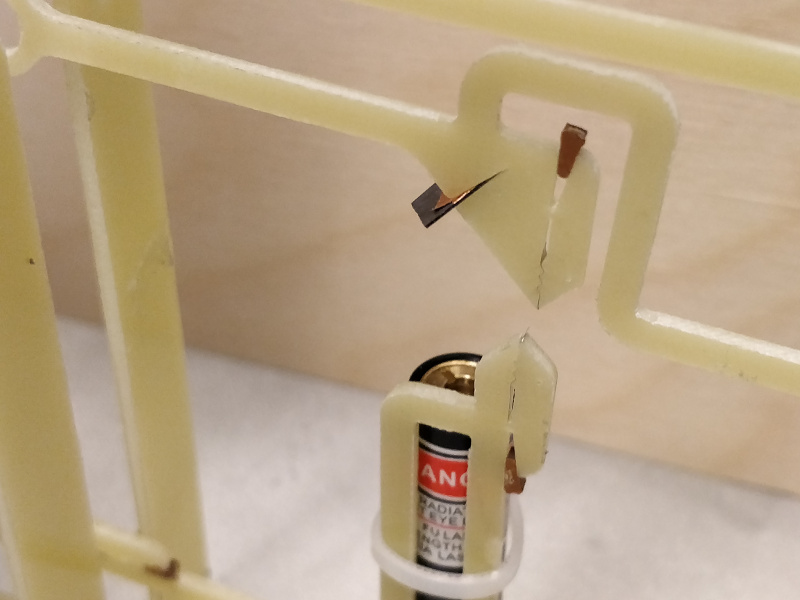 I hastily rebuilt the assembly fixture and cut a few fresh strips of foil; unfortunately, during reassembly the repeated strain on one of the 'fish' caused a more serious failure:
 I threw a hail-mary pass and got out the fancy quick-set epoxy, eschewing repairability for a last attempt at functionality:
 It worked! After a suitable cure time, I popped the flexure out of the fixture and quickly dropped it into the now-mostly-finished enclosure.
electronics
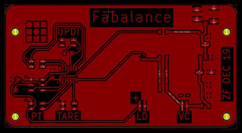
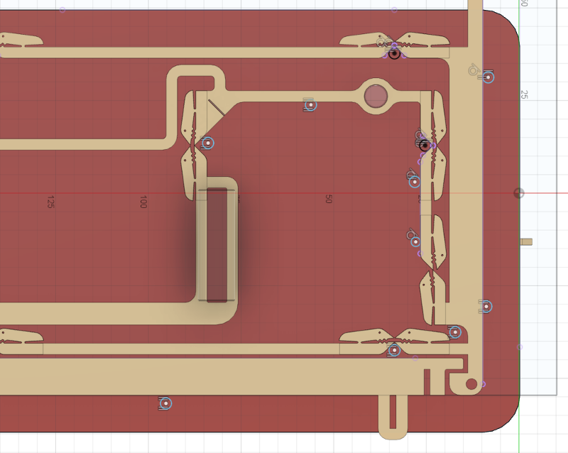
Neil has gotten excited about the new ATtiny 416 and 1614; they're priced like other ATtinys but have ATmega-like capabilities, along with a novel programming protocol called UPDI that eliminates the need for a dedicated ISP dongle. He gave me a bit of cut tape with a few of each processor, so I decided to give the platform a go for this project. Electronically, the microcontroller reads the differential signal between two phototransistors and adjusts the PWM duty cycle of the signal feeding the voice coil actuator, via an N-channel MOSFET. The scale also has a simple 8x2 LCD display and a big tare switch.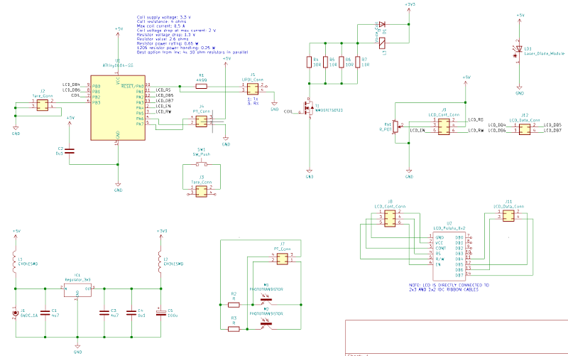 I designed the PCB to be somewhat modular, breaking out the various offboard components into 2x2 and 2x3 headers or (in the case of the diode laser and voice coil) solder pads. I had previously left a generous 40 mm x 100 mm bolt pattern on the aluminum base plate, so PCB layout was simple and uncrowded:
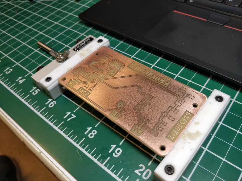
 I set my design rules to 0.5 mm / 0.5 mm and milled the PCB on the CBA's SRM-20:
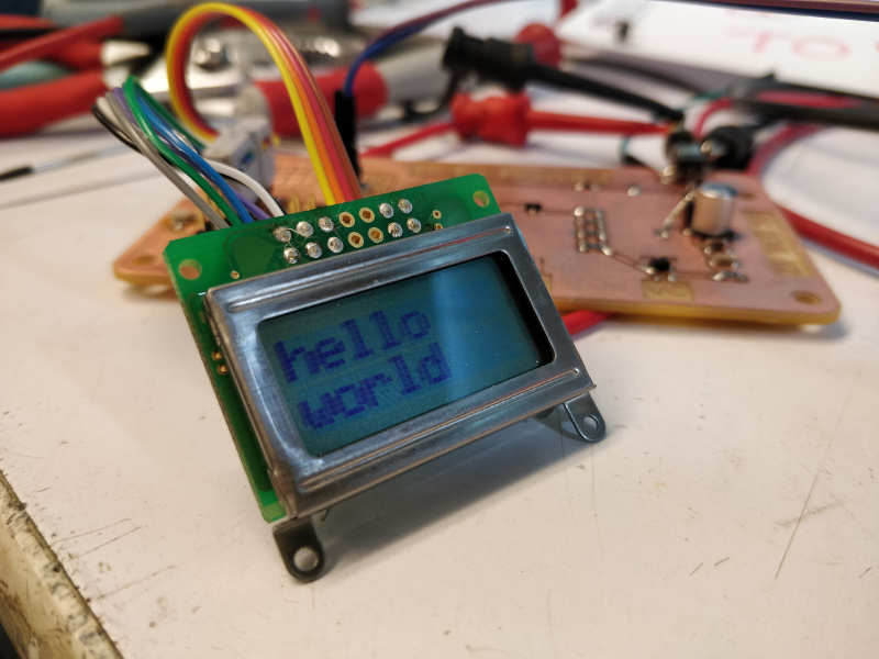
 I then used the megaTinyCore ATtiny1614 Arduino core to program the board, and Pololu's LCD library to get PCB woken up:
 I also twiddled the TCA registers on the t1614 until I got a 40 kHz PWM signal driving the coil, which stayed above the audio range and gave me ~10 bits of output resolution. Assembled with the scale, this allowed me to fully test the mechanism with the coil for the first time:
Unfortunately, getting the LCD and the coil working at the same time proved evasive. It seems that the LCD library is hard-coded to use the same timer I'd selected for the PWM output, either directly or via Arduino defaults. Bah, this always seems to happen with third-party microcontroller libraries: they work in isolation, but the inherently resource-limited nature of embedded development makes intercompatibility challenging. For the class demo, I kept the LCD physically installed but decided to demonstrate the coil functionality.
I also twiddled the TCA registers on the t1614 until I got a 40 kHz PWM signal driving the coil, which stayed above the audio range and gave me ~10 bits of output resolution. Assembled with the scale, this allowed me to fully test the mechanism with the coil for the first time:
Unfortunately, getting the LCD and the coil working at the same time proved evasive. It seems that the LCD library is hard-coded to use the same timer I'd selected for the PWM output, either directly or via Arduino defaults. Bah, this always seems to happen with third-party microcontroller libraries: they work in isolation, but the inherently resource-limited nature of embedded development makes intercompatibility challenging. For the class demo, I kept the LCD physically installed but decided to demonstrate the coil functionality.
thoughts
This project has been a delightful if somewhat underresearched exploration into sensitive flexure design and digital fabrication. I say underreachered because I never got my hands on a commercial analytical balance to take apart, and I never undertook a comprehensive literature review to see how other folks have solved the problems I faced. That was kind of the point, to be honest; fab class gave me a chance to try to recreate the last few decades of analytical balance design entirely from the 80s-era diagram I found earlier this semester: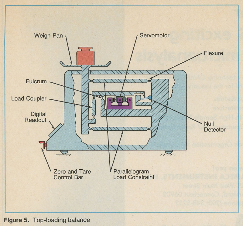 It was a fun exercise to say the least, and Fabscale helped me get up to speed on a number of machines that will be important during my time at CBA: the Roland MDX-540 4-axis desktop mill; the Sodick SL400G wire-EDM; the humble Roland SRM-20 PCB mill; the Adams Maxwell coil winder; and, since I decided to be fancy with my stainless flexures and scale baseplate, the Oxford laser micromachining system and the OMAX water jet cutter. With the possible exception of the voice coil actuator metal piece (which is wire-EDMed), everything else can be easily manufactured in a FabLab; I think the electromagnet could be redesigned around easier methods too, likely with a significant loss of efficiency. Or maybe this is good motivation to push the Desktop Wire-EDM project further (hint hint, Will...).
The next step for the Fabalance is another redesign of the flexure mechanism. After a good deal of pondering, I've decided that a stainless steel frame with spot-welded stainless steel foil flexures is worthy of exploration; both parts are easy enough to fabricate, welded joints are strong, and stainless steel foil seems like an ideal flexure material. To do this, I'd like to explore fabricating a simple micro-spot welder designed specifically for making precision flexures; ideally, it would make more of a uniform line than a spot, and would be integrated (or at least compatible with) a flexure assembly fixture.
I'd also like to take a closer look at the electronics portion of the project. I think it's feasible to integrate all of the functionality a scale needs into the ATtiny1614, and I'm a big fan of using simple and cheap microcontrollers whenever possible. But I want to give the sensing side another look; AFMs use quad photodiodes to compensate for off-axis motion, which seemed to be one source of drift for my sensor. As an alternative, I'd like to try a neat sensing method we used in my micro/nano fab class this semester (2.675). The lab used home-built atomic force microscopes based on Scott Manalis and Maxim Shusteff's design from 20.309, which are based on a MEMS interdigitated (ID) interferometric finger apparatus as the target for the laser rather than a simple mirror. As the ID assembly displaces, the fingers produce a constructive and destructive interference pattern that repeats every 1/4 wavelength (roughly 160 nm). A huge advantage of this setup is its relative insensitivity to misalignment; while adding a custom MEMS device to the scale may seem to go against the fabricability requirement, it is a good excuse to test Prashant's laser-based direct-write MEMS fabrication techniques on a real application.
It was a fun exercise to say the least, and Fabscale helped me get up to speed on a number of machines that will be important during my time at CBA: the Roland MDX-540 4-axis desktop mill; the Sodick SL400G wire-EDM; the humble Roland SRM-20 PCB mill; the Adams Maxwell coil winder; and, since I decided to be fancy with my stainless flexures and scale baseplate, the Oxford laser micromachining system and the OMAX water jet cutter. With the possible exception of the voice coil actuator metal piece (which is wire-EDMed), everything else can be easily manufactured in a FabLab; I think the electromagnet could be redesigned around easier methods too, likely with a significant loss of efficiency. Or maybe this is good motivation to push the Desktop Wire-EDM project further (hint hint, Will...).
The next step for the Fabalance is another redesign of the flexure mechanism. After a good deal of pondering, I've decided that a stainless steel frame with spot-welded stainless steel foil flexures is worthy of exploration; both parts are easy enough to fabricate, welded joints are strong, and stainless steel foil seems like an ideal flexure material. To do this, I'd like to explore fabricating a simple micro-spot welder designed specifically for making precision flexures; ideally, it would make more of a uniform line than a spot, and would be integrated (or at least compatible with) a flexure assembly fixture.
I'd also like to take a closer look at the electronics portion of the project. I think it's feasible to integrate all of the functionality a scale needs into the ATtiny1614, and I'm a big fan of using simple and cheap microcontrollers whenever possible. But I want to give the sensing side another look; AFMs use quad photodiodes to compensate for off-axis motion, which seemed to be one source of drift for my sensor. As an alternative, I'd like to try a neat sensing method we used in my micro/nano fab class this semester (2.675). The lab used home-built atomic force microscopes based on Scott Manalis and Maxim Shusteff's design from 20.309, which are based on a MEMS interdigitated (ID) interferometric finger apparatus as the target for the laser rather than a simple mirror. As the ID assembly displaces, the fingers produce a constructive and destructive interference pattern that repeats every 1/4 wavelength (roughly 160 nm). A huge advantage of this setup is its relative insensitivity to misalignment; while adding a custom MEMS device to the scale may seem to go against the fabricability requirement, it is a good excuse to test Prashant's laser-based direct-write MEMS fabrication techniques on a real application.
~december update: flexure foibles
or, "how to not fabricate highly sensitive flexural mechanisms" In the last few minutes of the final How to Make lecture before the final project showcase, Neil talked about demand- versus supply-side scheduling and spiral development. The former concept is about proactively planning and allocating time so that all facets of a complex problem can be addressed by a deadline; the latter is about iterating full prototypes of a concept rather than spending all of one's time on a particular aspect. Reader, I did not follow this advice. To be fair, I gave out this advice many times during the semester, and even felt at times that I needed to focus on other parts of the final project beyond the core mechanism; but here we are, a few days before the project presentation, and the majority of my time has been spent on sorting out the scale's magneto-optical feedback structure. Between documenting the optical feedback mechanism prototype in week nine and showing up for class an hour later (document as you go!), the powerful magnets attached to the acetal flexure unexpectedly snagged a metal plate and ripped one of the flexural elements apart. As I tried to recover parts of the mechanism for a class demo, more hair-thin acetal flexures snapped, leaving me with a sad pile of white plastic on my desk. I'm glad I got the pictures and videos I did when the mechanism was working, but the fragility of the system left me concerned about the durability of the finished scale. Time to shift gears.wire-EDM adventure
I decided to try to recreate the monolithic flexure in metal. Specifically, I wanted to use wire-EDM cut aluminum plate; while it's a bit stiffer than the acetal, my hope was that I could achieve tighter tolerances with the EDM process and end up with a more precise (and hopefully, more durable) flexure. I spent a good bit of time chasing down wire-EDM problems; when these were mostly resolved, I finalized an updated design for the component: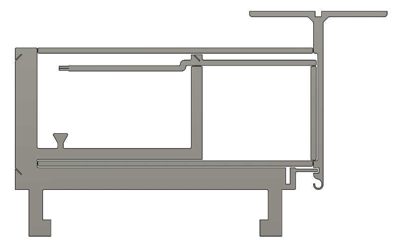 This design required three separate wire-EDM cuts; two internal operations and one external cut to free the mechanism. I pre-drilled holes in the appropriate spots in a 2 mm aluminum plate, fixtured it in the machine, and spent the next few hours watching the Sodick break wires. I figured out that the high pressure water jet was vibrating the plate, snapping the wire; this didn't happen with 2.4 mm 17-4 because the stainless stock is much stiffer than aluminum.
Following Will Langford's lead, I bolted a few aluminum plates together and got the first internal cut to work. Unfortunately, the waste slug of metal got wedged in the cut and contacted the wire-EDM's plastic nozzle, stalling the machine and putting a small nick in the [consumable, cheap] part. Since stalls require a machine restart, I lost the zero point of the cut and wasn't able to get the second operation aligned:
This design required three separate wire-EDM cuts; two internal operations and one external cut to free the mechanism. I pre-drilled holes in the appropriate spots in a 2 mm aluminum plate, fixtured it in the machine, and spent the next few hours watching the Sodick break wires. I figured out that the high pressure water jet was vibrating the plate, snapping the wire; this didn't happen with 2.4 mm 17-4 because the stainless stock is much stiffer than aluminum.
Following Will Langford's lead, I bolted a few aluminum plates together and got the first internal cut to work. Unfortunately, the waste slug of metal got wedged in the cut and contacted the wire-EDM's plastic nozzle, stalling the machine and putting a small nick in the [consumable, cheap] part. Since stalls require a machine restart, I lost the zero point of the cut and wasn't able to get the second operation aligned:
 Keen observers will notice the offset flexure in the lower-right corner of the image above, as compared to the CAD model. I started to be concerned about putting all of my eggs in the wire-EDM basket; even if the aluminum design had cut properly, it would have taken all day to finish. I then attempted a hybrid approach; wire-EDMed flexural inserts in a machined fiberglass frame. I started with a simple CAD sketch:
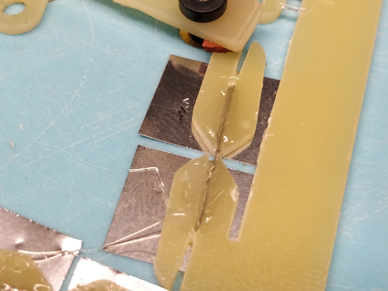
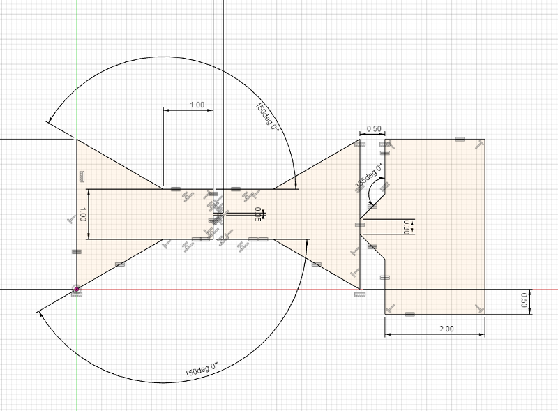 I manifolded the parts together and tried cutting them with a number of different flexure thicknesses: 50 microns, 100 microns, 150 microns. In all cases, the aluminum flexure disintegrated in the machine, leaving me with a pile of dogbone halfs. 17-4 and 304 stainless fared better:
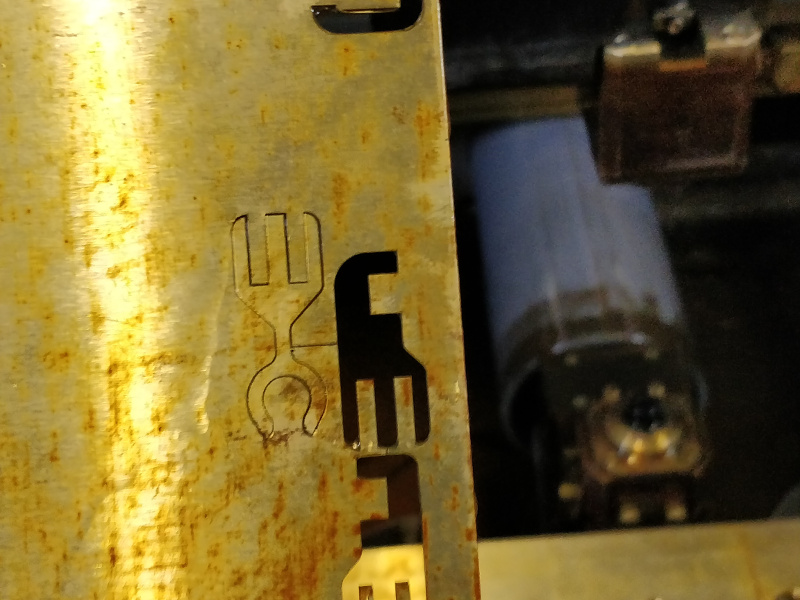
These parts fit nicely in a fiberglass support I machined; however, they proved to be substantially more stiff than the acetal flexure, and even the 304 stainless ones broke quite easily. The image below shows a close-up of a part getting ready to snap:
 Oof. Surface finish issues? Dial in the machine offsets? Or is it time for another major course-correction? I took a break and had a chat with Jake. Back to the drawing board with less than a week to go.
this project is now fish themed
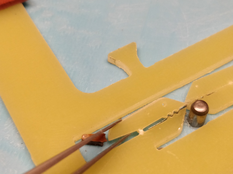
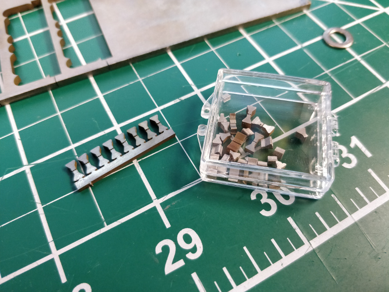
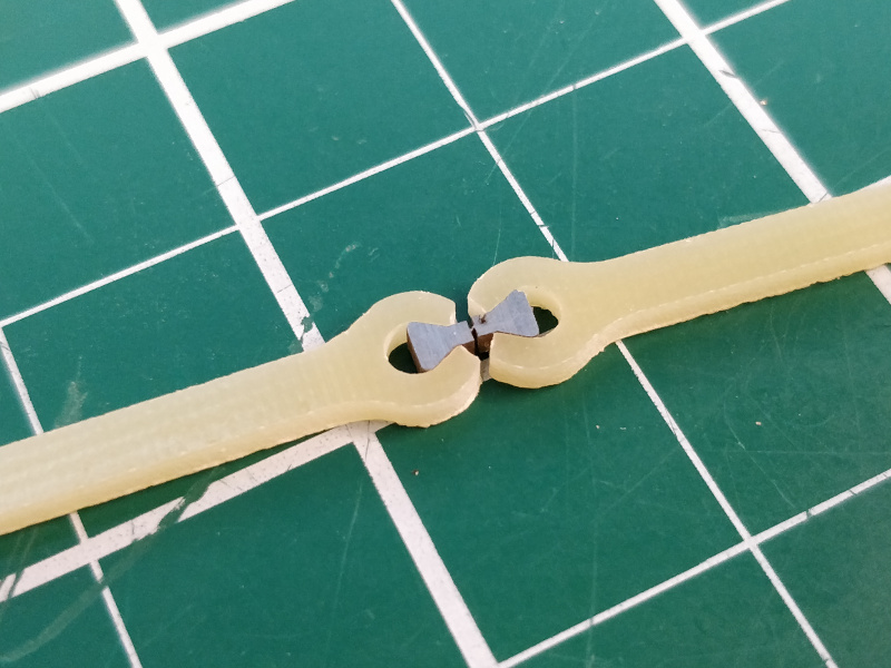
You know what makes a great flexure? Thin sheet stock. That hasn't changed since week one, when I explored using polyamide tape pin joints and a 3D printed frame. I decided to revisit this concept with a minor material change: 12.7 um stainless steel foil for the hinge and machined 1.68 mm G10 fiberglass composite for the structure. The meat-and-potatoes of this strategy is the connection between the metal foil and the fiberglass frame. One straightforward solution is to use a high performance adhesive; there are plenty of 2-part epoxies that are happy to glue stainless to composite. Instead, I decided on an approach that is larger, more complex, more finicky, and more delicate, but allows one to swap in replacement flexures should the foil break. Here is the first joint prototype: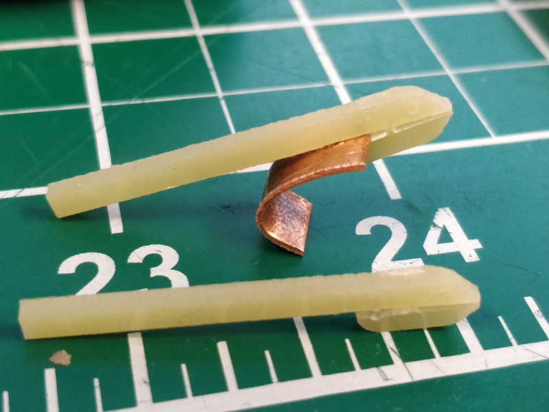 See? Fish themed! The G10 machined beautifully on the MDX-540 with 1/8" and 1/64" carbide tooling. The copper 'cape' wedges the fish's 'mouth' closed over the foil; two opposed fish in close proximity (kissing? is that weird?) biting down on the stainless should make a decent flexure, and removing the wedge allows the foil to be swapped. The first prototype worked decently well, but the foil slipped out quite easily; I fixed this on the second iteration by adding a few teeth:
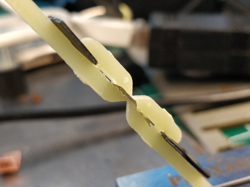 Here is a clip of a joint test using freshly machined parts from the finished scale design and proper phenolic wedges:
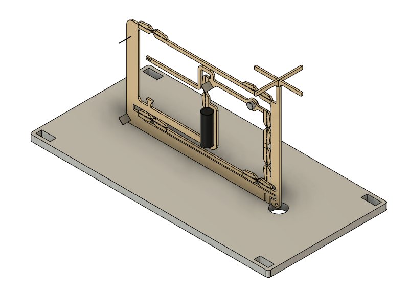
The joints could use another iteration. Specifically, the flexural elements would benefit from a bit more width; as it stands now, they are not very constrained and flop under off-axis forces. But the jaws seem to hold and the stainless bits are durable, so I decided to carry this design through to a full balance prototype. Here is the mechanism, including the laser, mirrors, and baseplate:
Here is a clip of a joint test using freshly machined parts from the finished scale design and proper phenolic wedges:
The joints could use another iteration. Specifically, the flexural elements would benefit from a bit more width; as it stands now, they are not very constrained and flop under off-axis forces. But the jaws seem to hold and the stainless bits are durable, so I decided to carry this design through to a full balance prototype. Here is the mechanism, including the laser, mirrors, and baseplate:
 I also designed an assembly fixture to hold the flexure stable while I wedge in the stainless strips. The machined fiberglass structure is located using pins and secured using to-be-designed clamps:
 I 3D printed the fixture which was a pretty poor choice of fabrication methods. It does have blind holes for heat set inserts, but the whole thing is really just a 2D cut. Definitely a better fit for the laser cutter, but here we are:
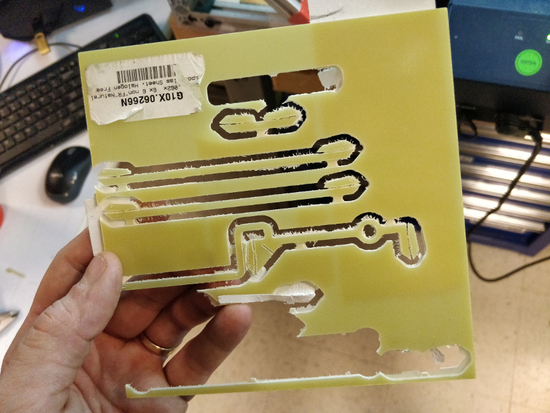
 I cleaned the surface of the fixture up with a bit of sanding. I also machined the G10 bits, being sure to carefully vacuum up all the nasty fiberglass dust:
I probably could have dropped the Z axis a few tenths of a millimeter to cut down on 'fuzzing', but the parts cleaned up easily enough with a few scrapes of a razor blade:
I cleaned the surface of the fixture up with a bit of sanding. I also machined the G10 bits, being sure to carefully vacuum up all the nasty fiberglass dust:
I probably could have dropped the Z axis a few tenths of a millimeter to cut down on 'fuzzing', but the parts cleaned up easily enough with a few scrapes of a razor blade:
 Next, Alfonso helped me water jet a chunk of 1/4" aluminum for the baseplate. Ooof, what a machine:
Then I used the Oxford laser micromachining system to cut out a few stainless steel flexures:
Next, Alfonso helped me water jet a chunk of 1/4" aluminum for the baseplate. Ooof, what a machine:
Then I used the Oxford laser micromachining system to cut out a few stainless steel flexures:
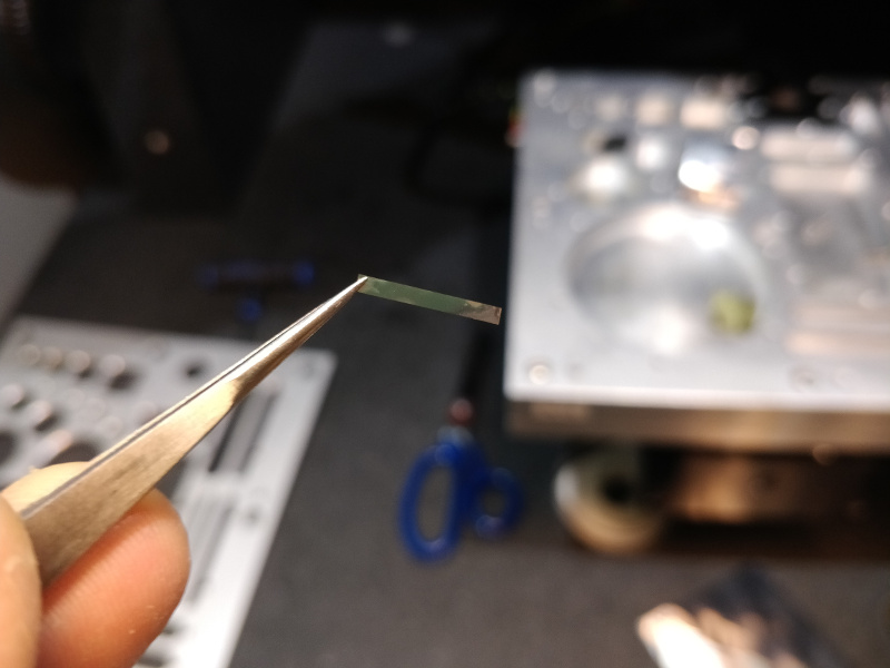 Clearly overkill; a bit of careful scissor work would have been fine. But it's a fun machine to use, and certainly one I need to keep honing my skills with. This time, I put my phone inside the safety enclosure so I could capture the 532 nm laser light:
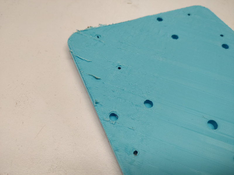
I installed guide pins and heat-set inserts in the cyan build plate, machined a handful of fiberglass clamps, and carefully aligned the flexure on the jig. I designed everything to nominal tolerances; a few parts required a bit of sanding to align perfectly, but once I was satisfied I secured everything with the clamps and a few bits of rubber to avoid slippage:
Clearly overkill; a bit of careful scissor work would have been fine. But it's a fun machine to use, and certainly one I need to keep honing my skills with. This time, I put my phone inside the safety enclosure so I could capture the 532 nm laser light:
I installed guide pins and heat-set inserts in the cyan build plate, machined a handful of fiberglass clamps, and carefully aligned the flexure on the jig. I designed everything to nominal tolerances; a few parts required a bit of sanding to align perfectly, but once I was satisfied I secured everything with the clamps and a few bits of rubber to avoid slippage:
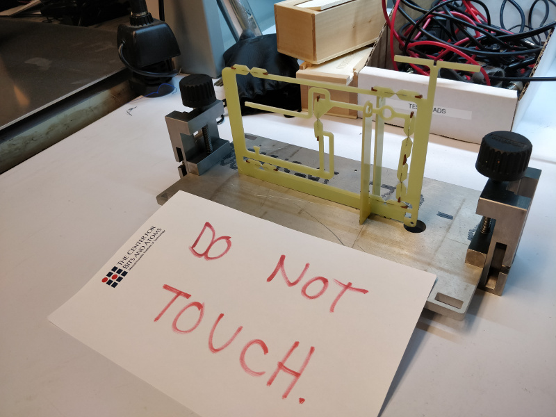
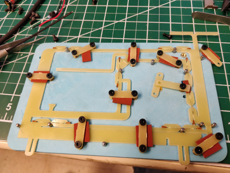 Two of the G10 pieces broke during assembly; in both cases, I was a bit too aggressive with the clamping wedges and popped the fish jaw off. Sorry li'l buddy! Fortunately, fiberglass machines quickly and I had enough spare stock to get by. Once the flexure was assembled, I carefully removed it from the fixture and installed it in the baseplate along with an important warning sign:
 I quickly modeled an actuator based on my work from week ten, slightly modifying the geometry to fit the flexure. I wire-EDMed the magnet bit from the same bit of steel stock I'd used earlier:
 ... and machined a fresh phenolic coil mandrel:
I installed the laser and two bits of polished silicon and gave the mechanism its first test. Here it is, moving between end stops as I vary the coil power:
T-51 hours, time to start thinking about electronics.
... and machined a fresh phenolic coil mandrel:
I installed the laser and two bits of polished silicon and gave the mechanism its first test. Here it is, moving between end stops as I vary the coil power:
T-51 hours, time to start thinking about electronics.
~november update
see week nine for the optical feedback mechanism, and week ten for the electromagnetic actuator.~october update: milling the acetal mechanism
test coupons
The heart of the analytical balance is the magneto-optical servo mechanism and associated circuitry. In order to provide repeatable measurements, the physical structure must be extremely sensitive to minute forces. Starting from 1/8" acetal, I modeled a simple beam in Fusion 360 and used the simulation functions to apply a 1 mg load 20 mm from a 0.2 mm flexure. The displacement results were disappointing: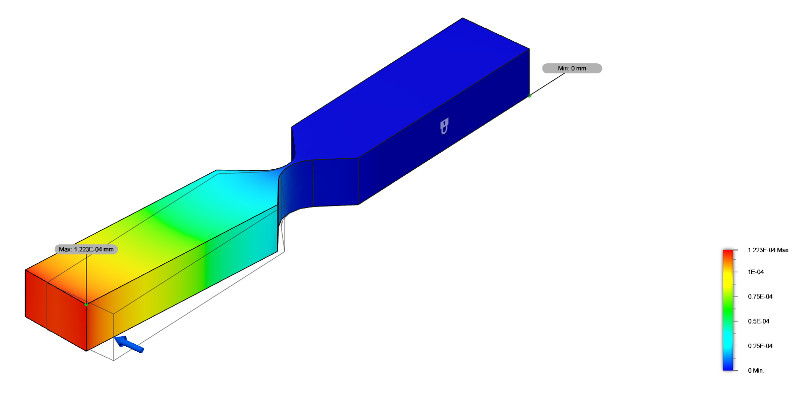 The annotation indicates 122 nm displacement under 1 mg load, which isn't nearly enough to reliably measure (since I don't want this to become an interferometer project). I changed to 0.8 mm acetal and a 0.02 mm elongated flexure and got much more favorable results:
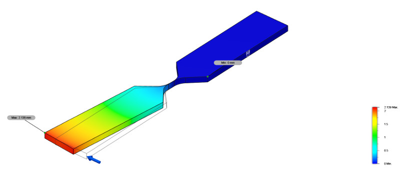 This beam displaces 2.14 mm under the same load! Jake brought up a good point though; since I elongated the flexure rather than keeping it a simple radius, it's no longer a contrained pin joint; the joint doesn't counteract shear forces, which will result in significant errors. But before we had that discussion, I spent some time on the SRM-20 milling test beams using a 1/32" end mill and two 0.016" passes over taped down 0.80 mm acetal sheet stock:
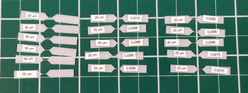 Initially, I set the gap in the Fusion 360 model to set values shown on the left: 20 um, 30 um, etc. After examining the beams using the Lynx Evo, I realized they were nowhere near the size I'd hoped; I estimated the width of the hinge at more than 100 um. Keeping the 20 um file, I gradually decreased the mill diameter value in mods and re-ran the file until I started getting much thinner beams; I estimate the thinnest I was able to mill to be 30-40 um. Eventually, I ended up with a beam that seemed worth testing, so I clamped the sample to my laptop screen with a bit of graduated paper and tried weighing an 0402 capacitor (which, according to our lab's analytical balance, weighs ~1.2 mg):
[command: ffmpeg -i VID_20190930_184936_01.mp4 -filter:v "scale=800:-1" -c:a copy out.mp4]
I call that optimistically inconclusive. In any case, it's time to design, model, simulate, and mill the full mechanism. And if all else fails, perhaps this will become an interferometer project.
Initially, I set the gap in the Fusion 360 model to set values shown on the left: 20 um, 30 um, etc. After examining the beams using the Lynx Evo, I realized they were nowhere near the size I'd hoped; I estimated the width of the hinge at more than 100 um. Keeping the 20 um file, I gradually decreased the mill diameter value in mods and re-ran the file until I started getting much thinner beams; I estimate the thinnest I was able to mill to be 30-40 um. Eventually, I ended up with a beam that seemed worth testing, so I clamped the sample to my laptop screen with a bit of graduated paper and tried weighing an 0402 capacitor (which, according to our lab's analytical balance, weighs ~1.2 mg):
[command: ffmpeg -i VID_20190930_184936_01.mp4 -filter:v "scale=800:-1" -c:a copy out.mp4]
I call that optimistically inconclusive. In any case, it's time to design, model, simulate, and mill the full mechanism. And if all else fails, perhaps this will become an interferometer project.
flexure prototype
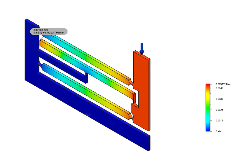
I used Fusion 360 to model a complete flexure mechanism. Initially, I included everything in a single sketch, and extruded it all into a 0.8 mm bit of acetal. Once I had a reasonable-looking result, I tried milling it on the SRM-20 with a healthy amount of sticky tape to hold down the stock. After a bit of careful cleaning, I got a pleasingly springy result: [command: ffmpeg -i VID_20191004_220751.mp4 -filter:v "scale=800:-1" -c:a copy out.mp4] At some point, the Fusion 360 model became complex enough that the flexure radii started causing problems when I modified other dimensions. The arcs that defined each flexure were dimensioned by degree and radius, which started causing unexpected constraint conflicts. I ended up remaking the model in several stages; first, I sketched, constrained, and dimensioned the general outline of the flexure; then, I extruded it in 0.80 mm acetal; then, I created a new sketch on the newly extruded surfaces that referenced its geometry and defined the flexure arcs; and finally, I extrude-cut the flexure arcs into the original model. I used Fusion 360's built-in static simulator to check displacement of the mechanism. I applied a force of 0.00001 N (close to 1 mg on Earth) to the top of the balance and watched the displacement of the sensed part of the mechanism: The result for a 50 um flexure is a bit tough to read; 0.0061 mm. Not very much. Among a number of other tests, I tried securing the upright flexure to simplify the milling procedure. For the same load, this reduced the displacement by ~18%:
 I also tried varying the position of the fulcrum, but didn't see any improvement in displacement.
mechanism tests
I have concerns about the sensitivity of the acetal mechanism. Per the simulations, if I'm able to reliably mill 50 micron flexures I can still only expect a few microns of displacement under a 1 mg load. My feeling is that this will be a stretch for an optical break-beam mechanism to detect; however, I still think the time is right to run a test that closes the electro-optical feedback loop. I started by milling a fresh flexure that included an interlocking piece for a coil form. Then I wound a coil using 34 AWG polyurethane insulated magnet wire; this was tedious enough that I lost track of winding count, but I'm guessing I made it ~60 times around (thanks Alfonso for snapping a picture):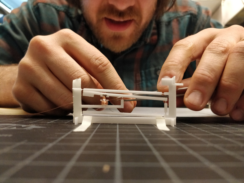 I hooked the mechanism up to the bench supply, set the voltage to 2 VDC, and slowly ramped up the current limit until the balance lifted off:
The mechanism reached equilibrium around 0.80 A and 1.0 VDC; keen observers of the video will notice the telltale wisps of smoke coming off the coil as I increased the current further. Clearly I need to model the electromagnetic circuit and optimize the design. Sounds like an excuse to play with COMSOL.
I hooked the mechanism up to the bench supply, set the voltage to 2 VDC, and slowly ramped up the current limit until the balance lifted off:
The mechanism reached equilibrium around 0.80 A and 1.0 VDC; keen observers of the video will notice the telltale wisps of smoke coming off the coil as I increased the current further. Clearly I need to model the electromagnetic circuit and optimize the design. Sounds like an excuse to play with COMSOL.